Otari MX-5050 Mini Pro

Gallery

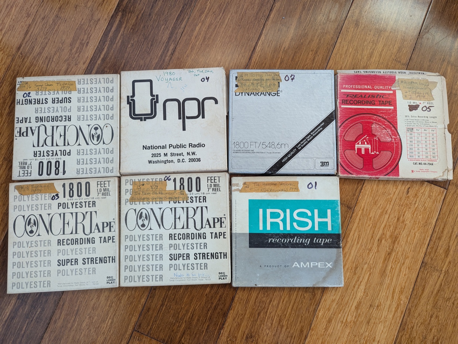
The machine this site is about — my first-generation Mini Pro — and the tapes that started it all. Working shots from the bench; proper beauty shots to come.
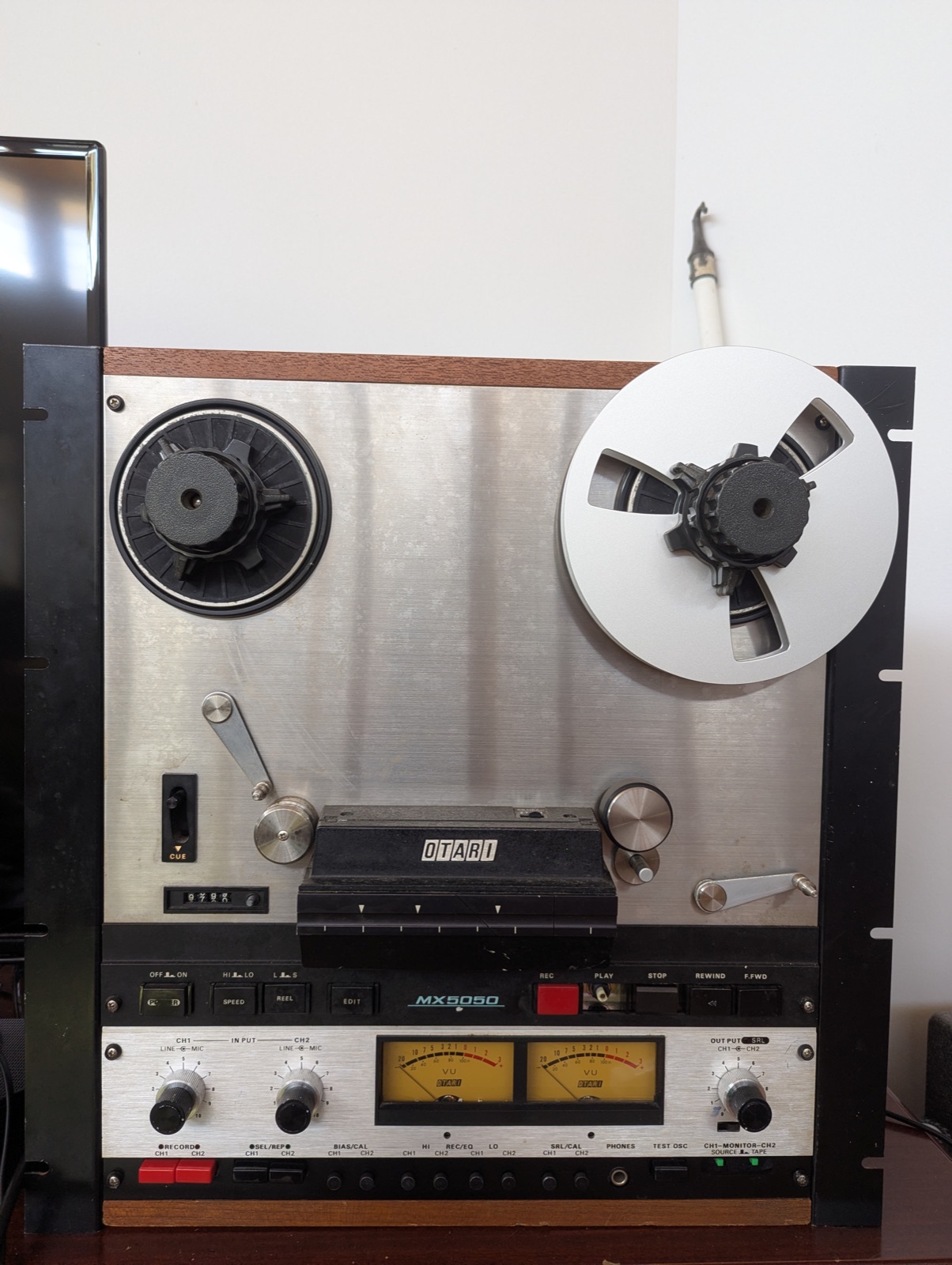
The Mini Pro today — rack brackets in place of the factory wood.
Where it started: Ted's reels, hand-labelled 1978–1980.
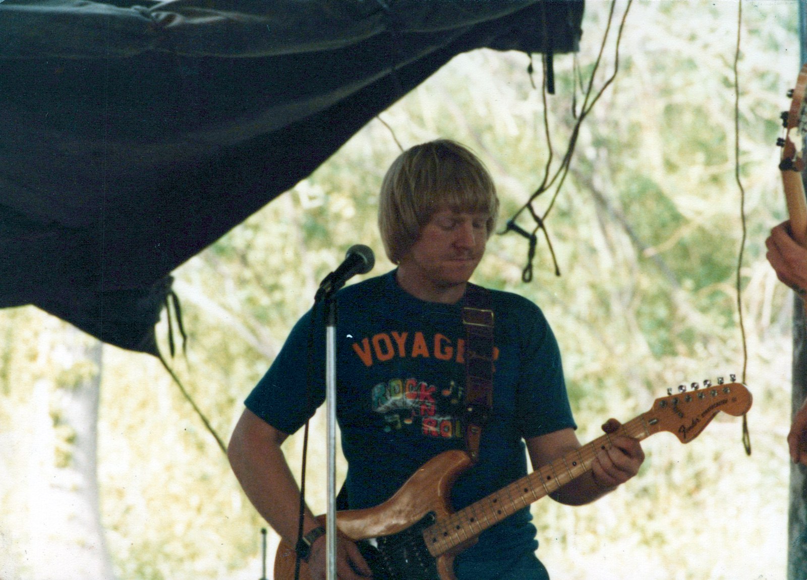
Ted on stage, 1980 — the man on the reels.
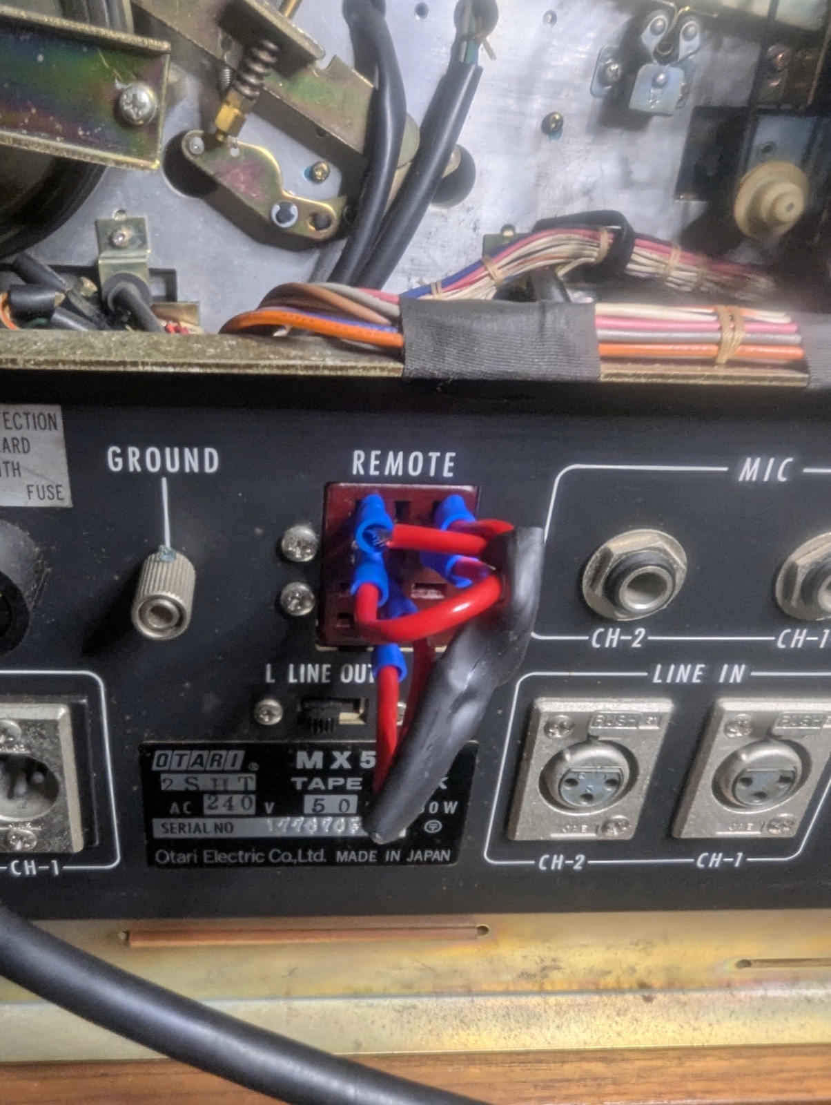
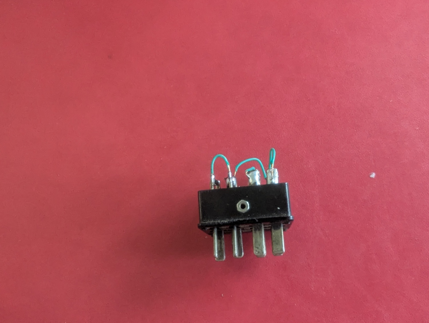
The Frankenstein dummy plug — automotive crimp ends in the remote jack.
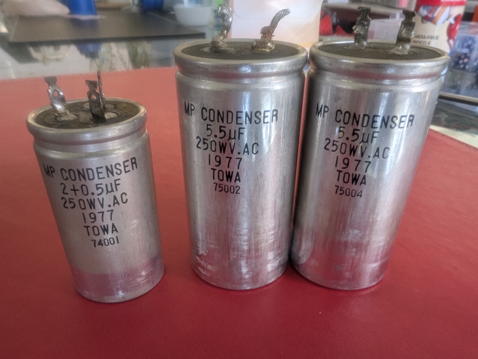
The 1977 TOWA motor-run caps, freshly pulled.
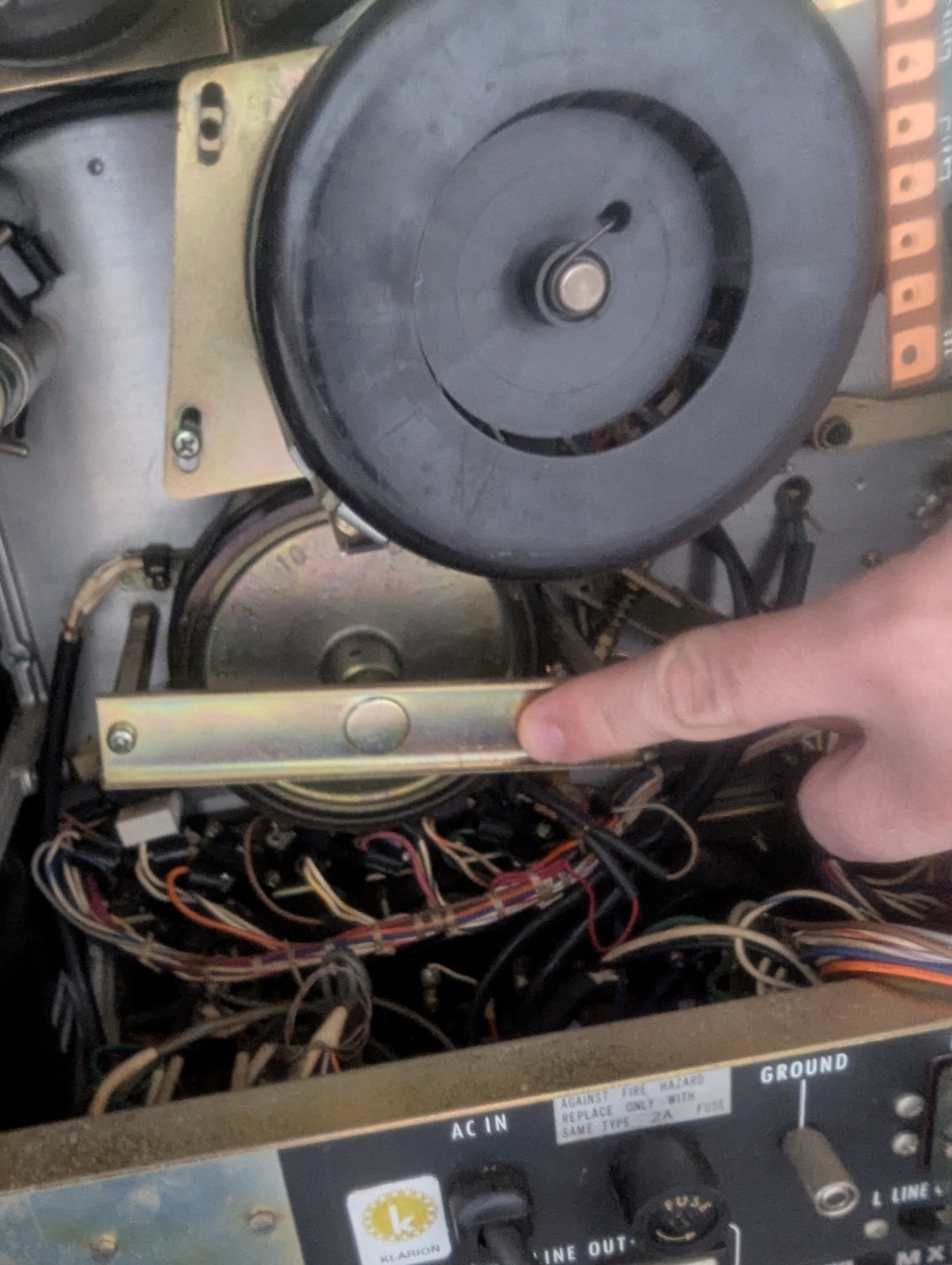
Belt-driven capstan flywheel — rules out every direct-drive generation.
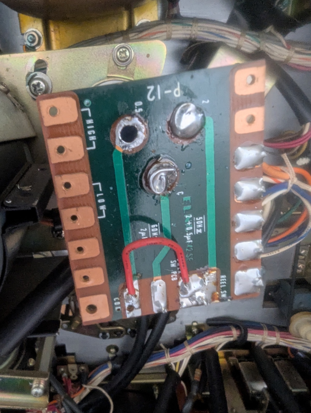
P-12 speed board after the re-cap.
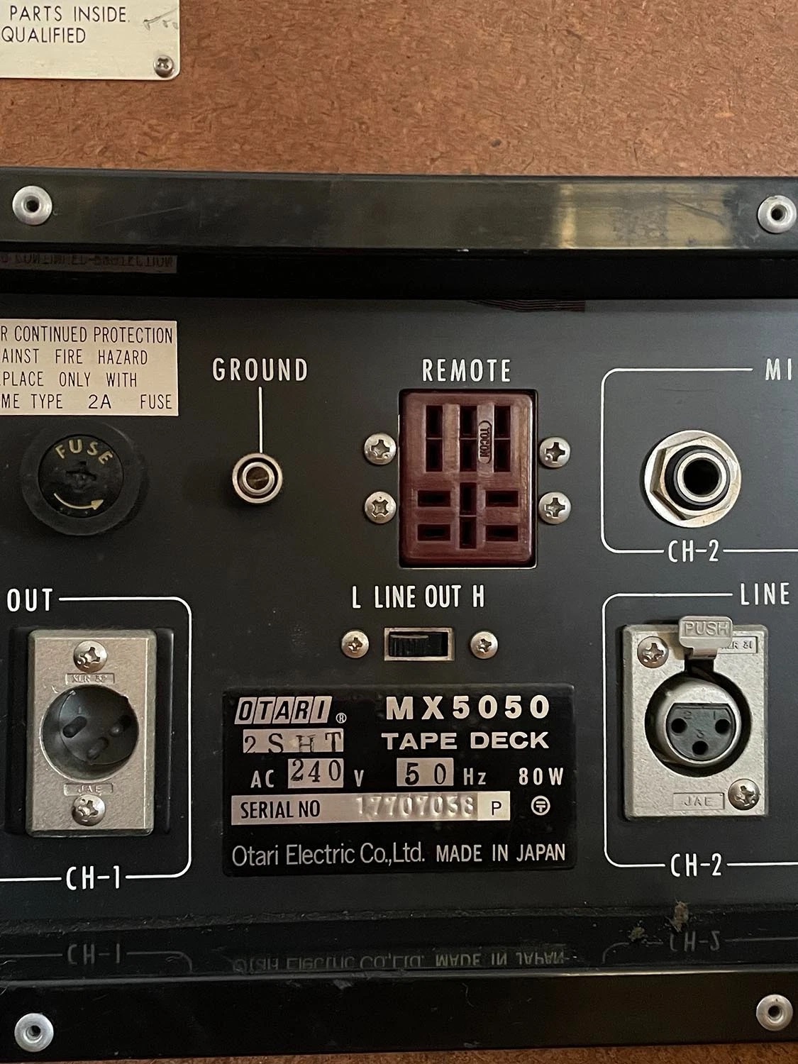
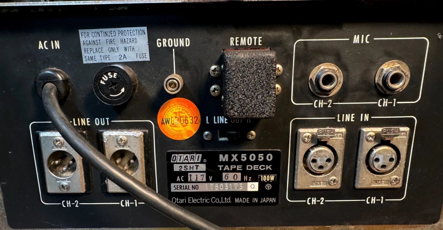
The rear jack panel — 2SHT model plate, remote socket still empty.
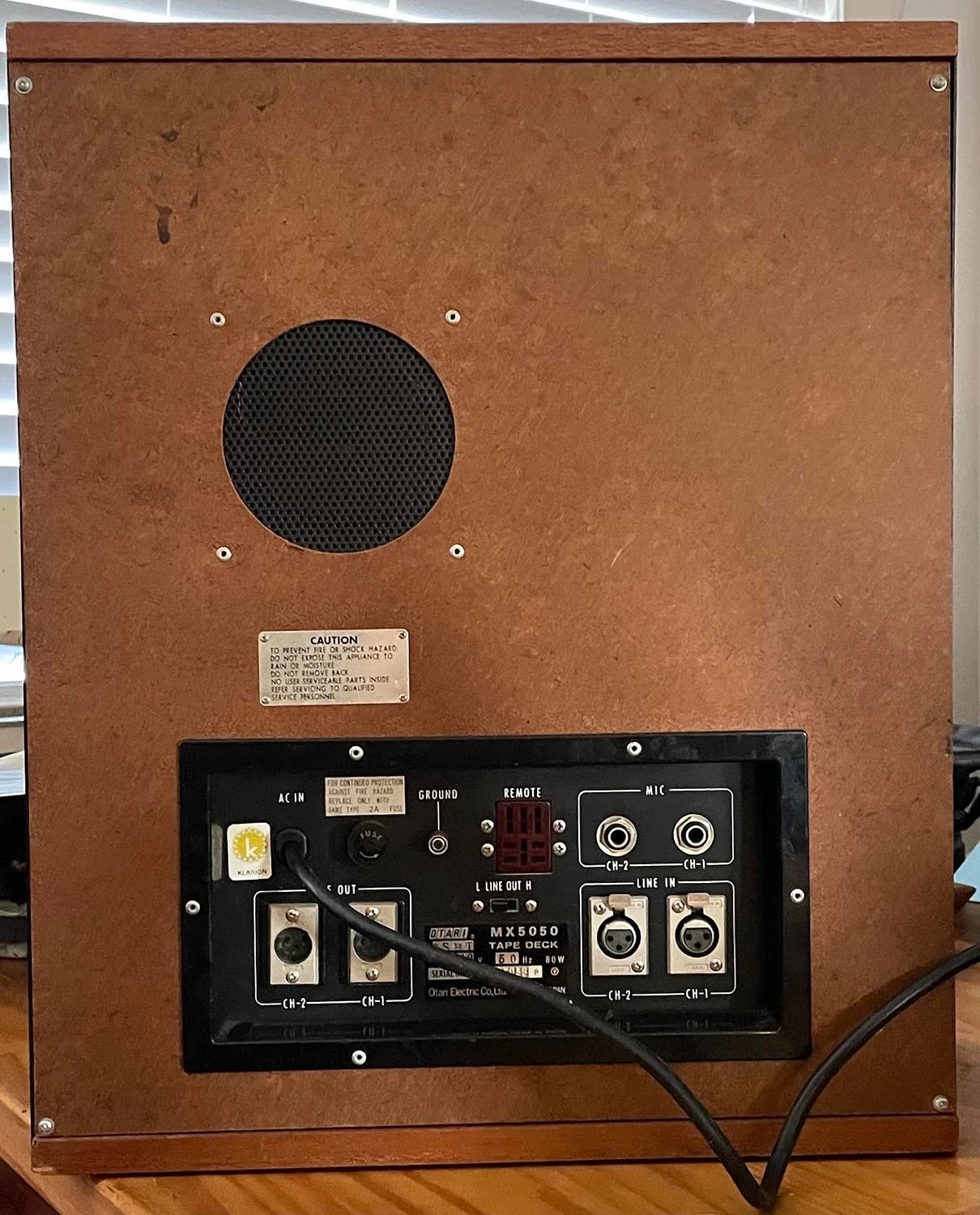
The factory walnut cabinet from behind — Klarion distributor sticker beside the AC inlet.
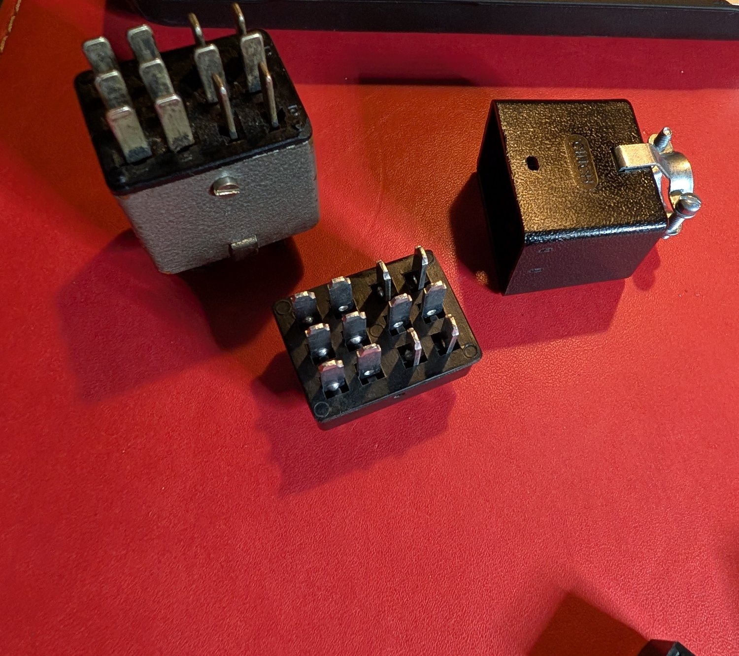
The tidy dummy plug — a vintage Cinch plug rewired with the 1–3–8–11 and 4–6 jumpers.
Cinch-Jones hardware, old and new — the vintage plug beside the modern body and hood.
The factory dummy plug on another first-generation deck — crinkle black in the REMOTE socket, easy to overlook.
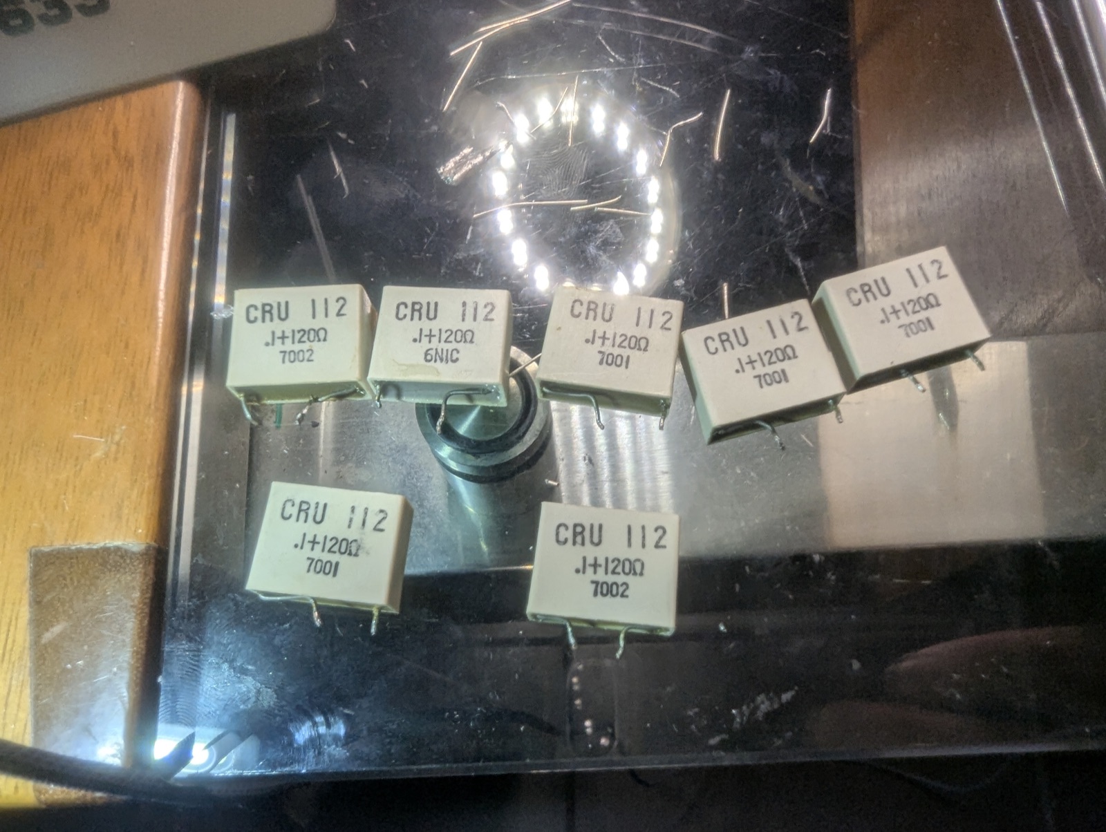
The switch board's spark quenchers, freshly pulled — 0.1 µF and 120 Ω, one across every switch on the board.
The switch board back in, with black X2-rated spark quenchers where the white 1977 blocks used to be.
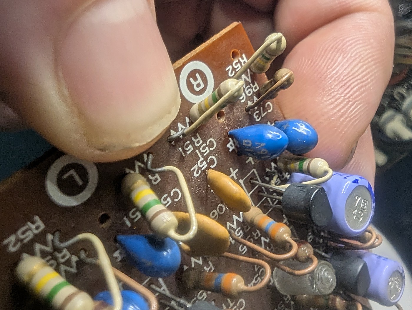
The replay-input corner before desoldering — 1977 tantalum beads on the head inputs.
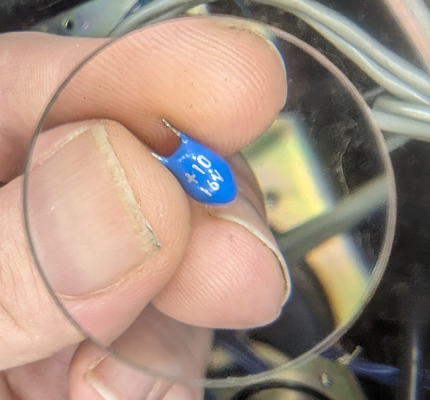
C51, the replay-head tantalum, minutes after desoldering — the first one out.
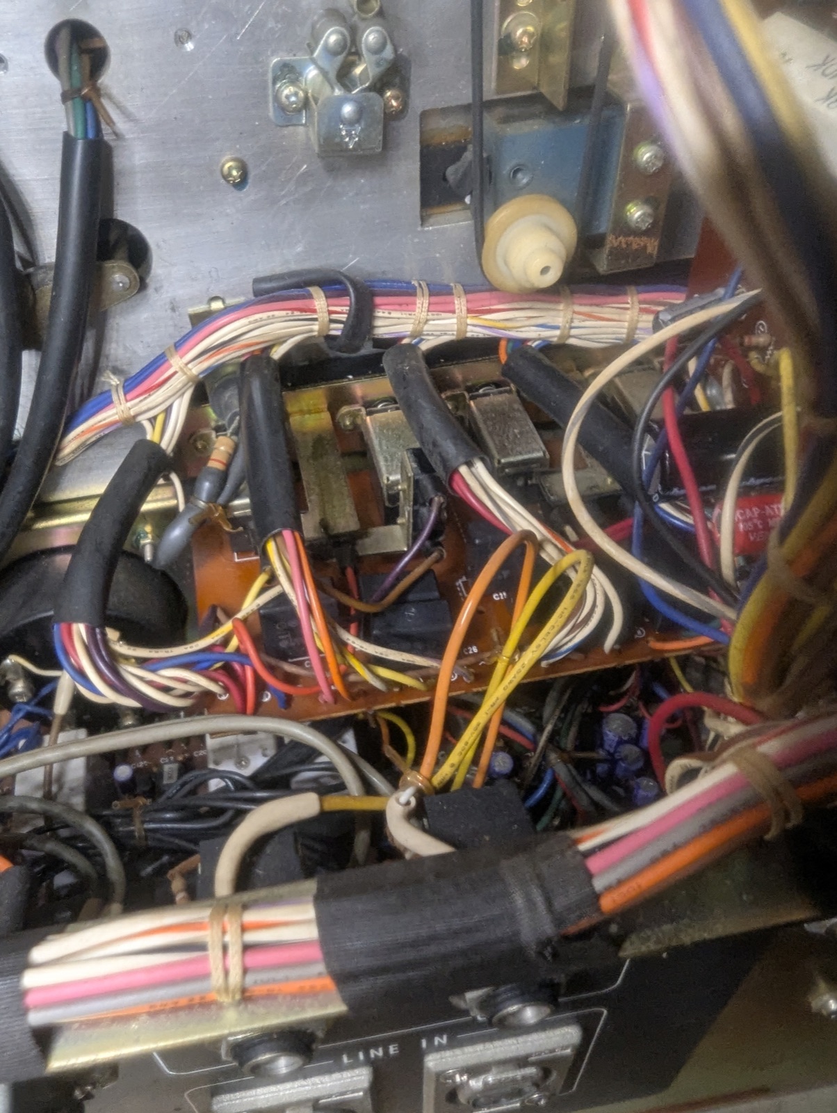
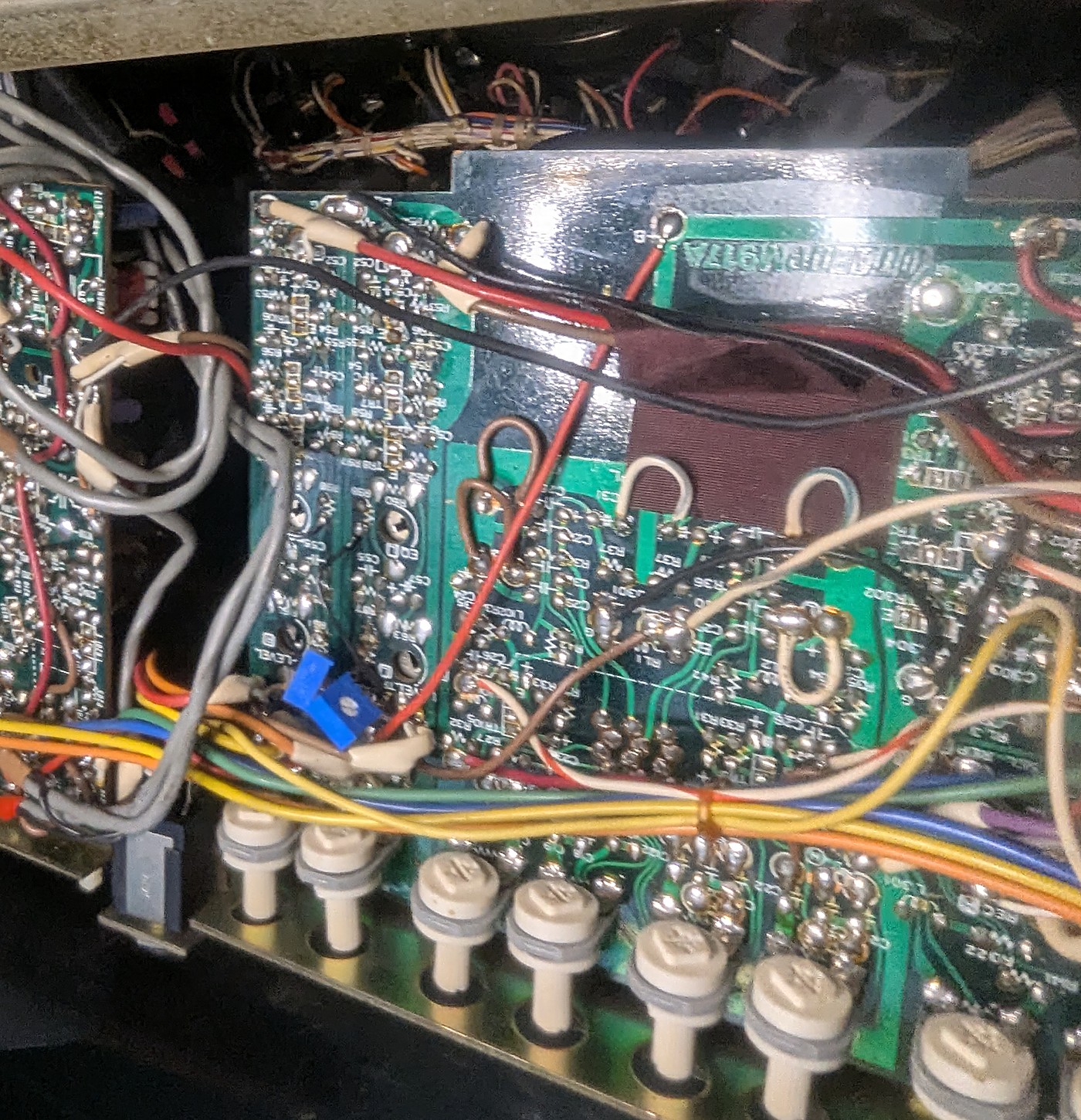
The rec/EQ board flipped solder-side up, still wired into the loom — the working method on a first-gen deck.
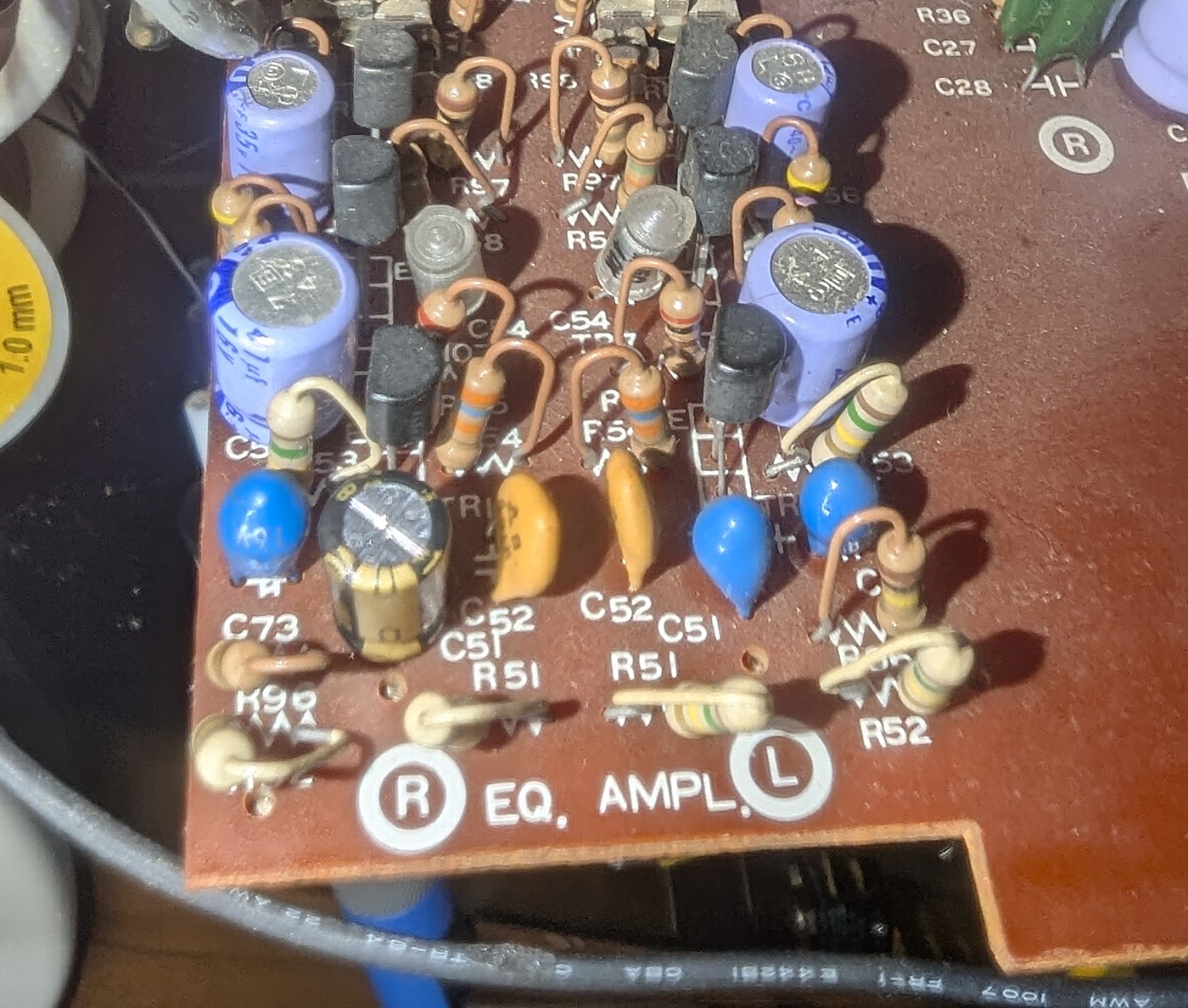
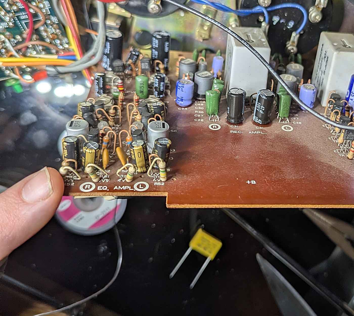
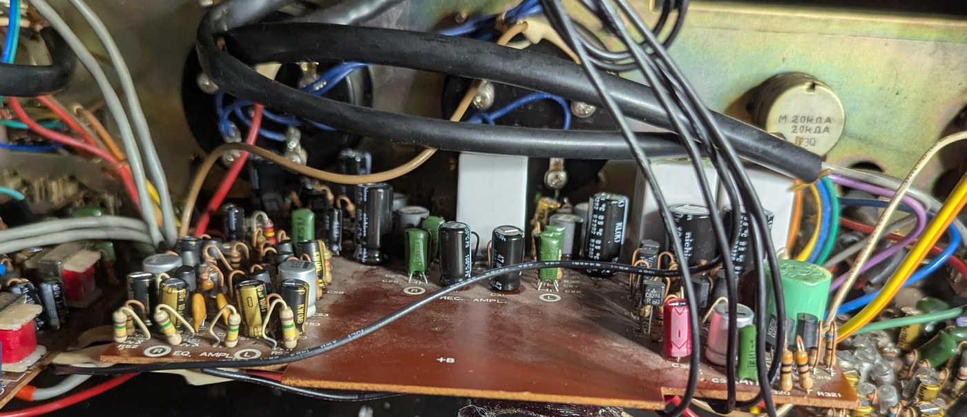
The EQ AMPL zone before session 1 — tantalum beads among the 1977 electrolytics.
The same zone after session 1 — modern cans at the head inputs, interstages and emitter bypasses.
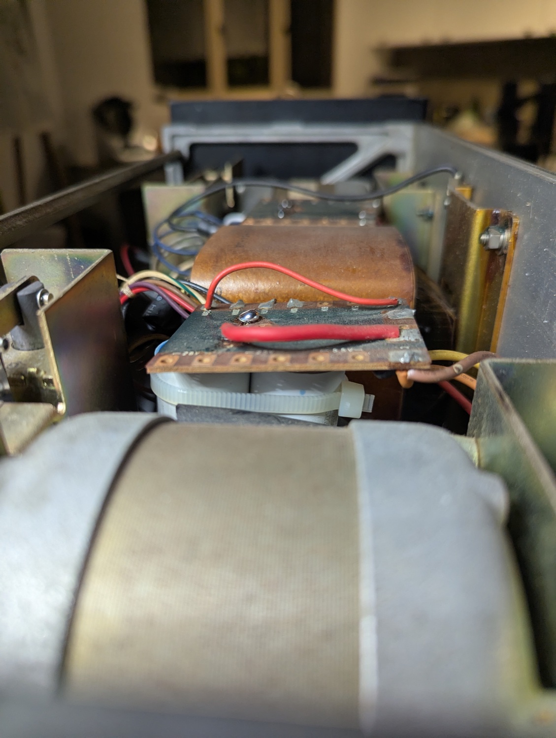
The paralleled 3 + 2.5 µF motor-run cans for a spindle motor, zip-tied beneath the voltage-selector board.
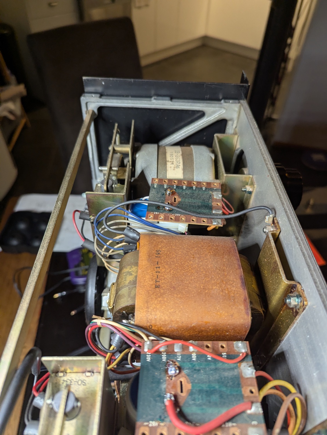
The electronics bay re-capped — new motor-run cans in the original, gently bent-in brackets.
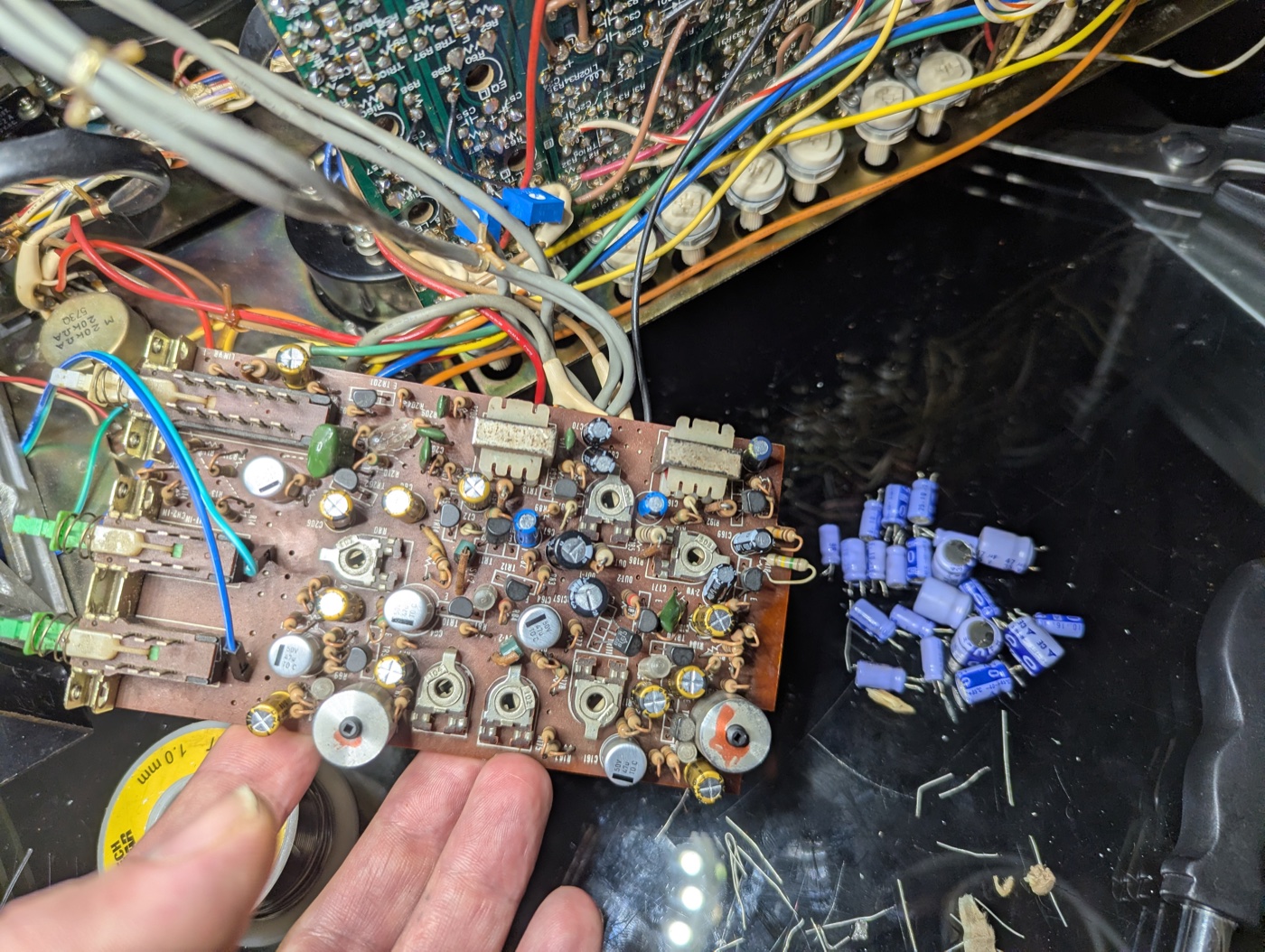
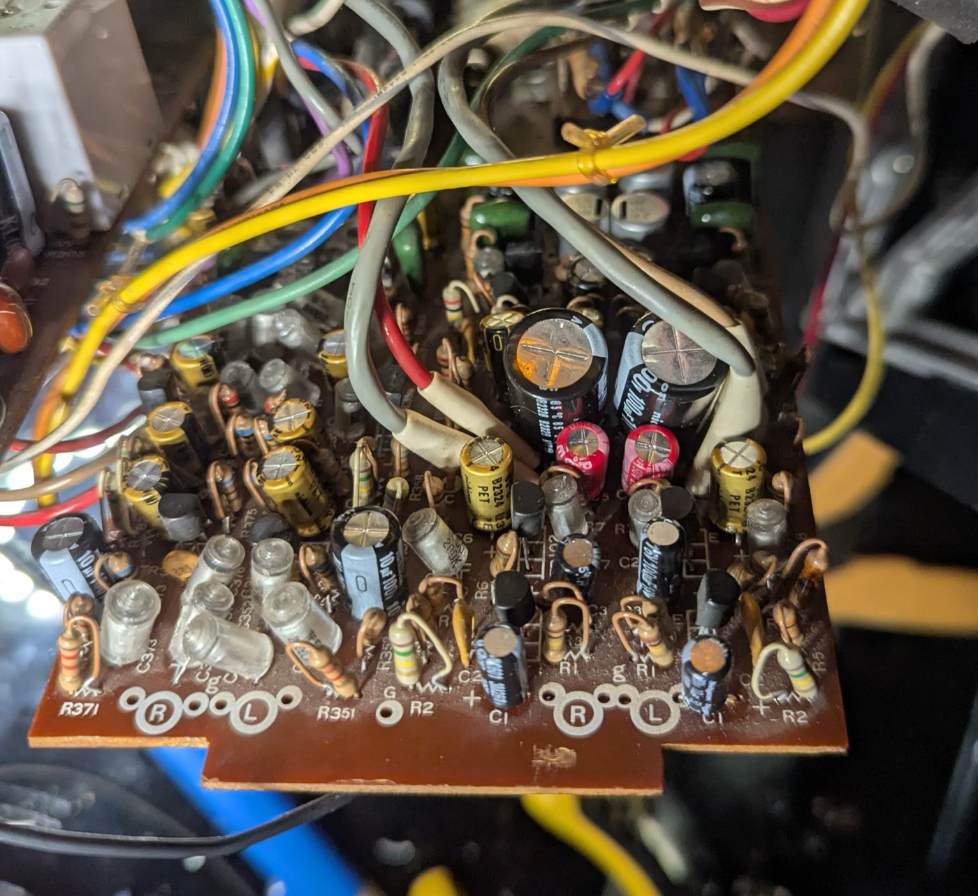
Session 2 done — the line-out board recapped in hand, the 1977 originals piled on the deck.
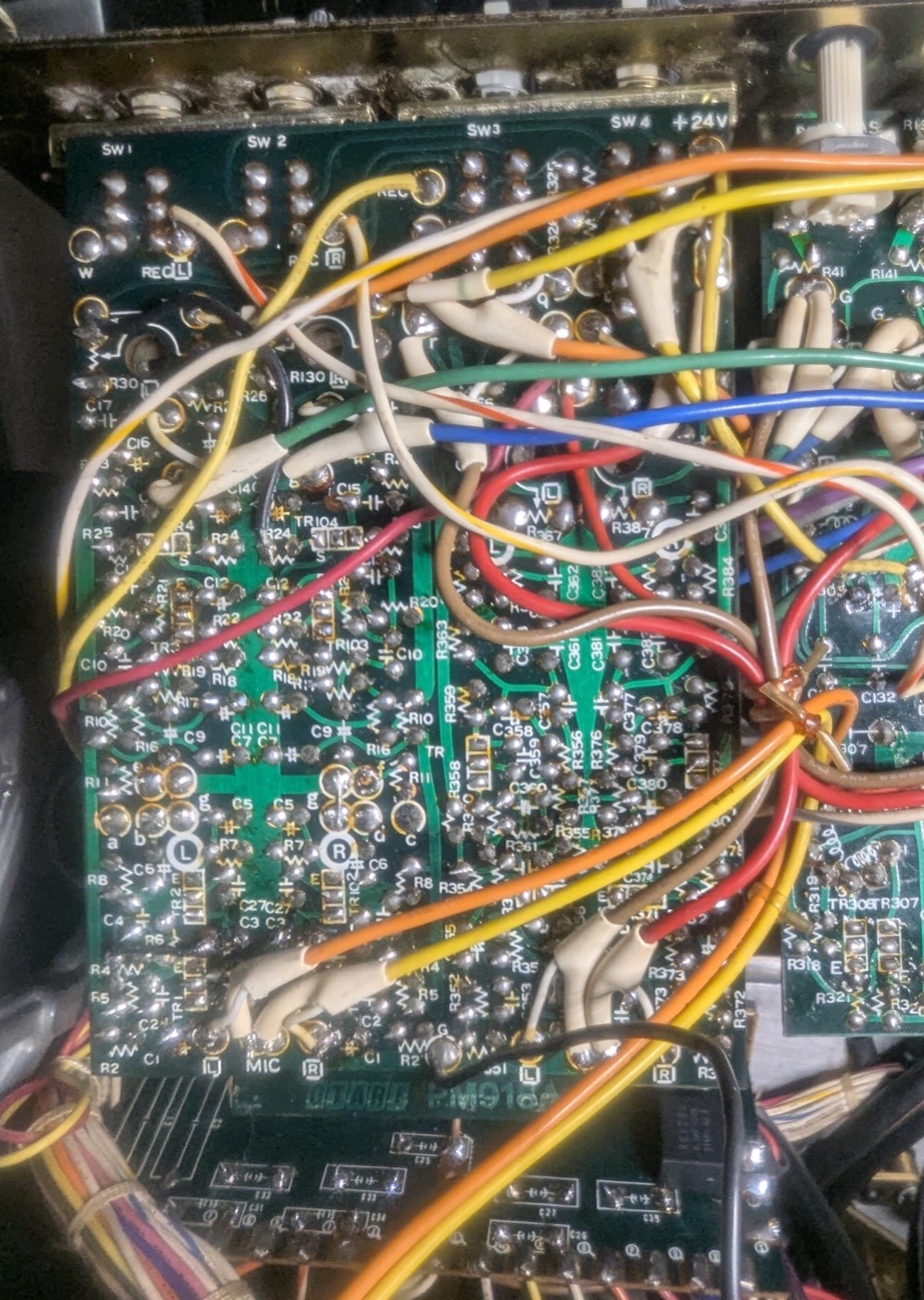
Session 3's working shot — the input board flipped solder-side up, the busiest board of the three.
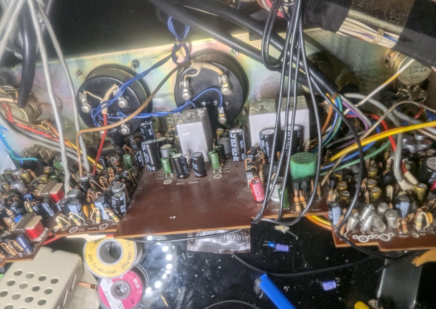
The record amplifier zone on fresh capacitors — the last all-original zone, done.
All three audio boards out on their looms at the end of session 3 — the whole audio path recapped.
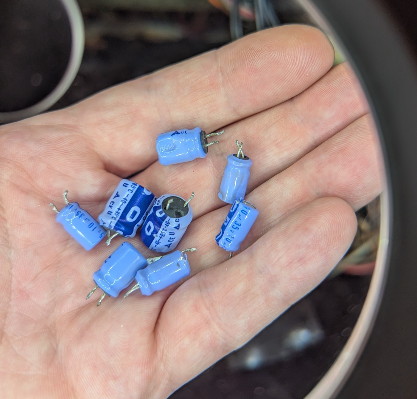
The last of the 1977 originals — pale blue cans with clipped leads, out for good.
PM917A — the record and EQ amplifier board, both zones on fresh capacitors.
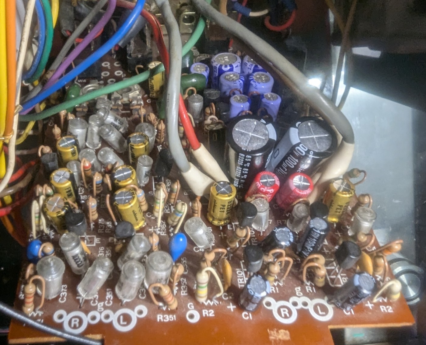
PM918A — the mic and line input board, component side, recapped.
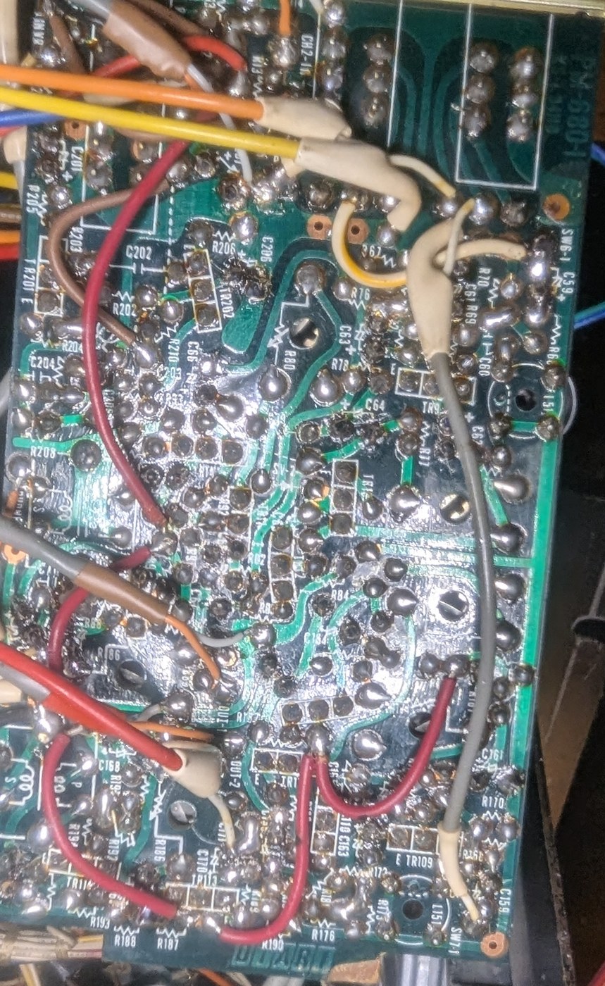
PM-680-1 — the line-out board from the solder side, fresh joints across the audio path.
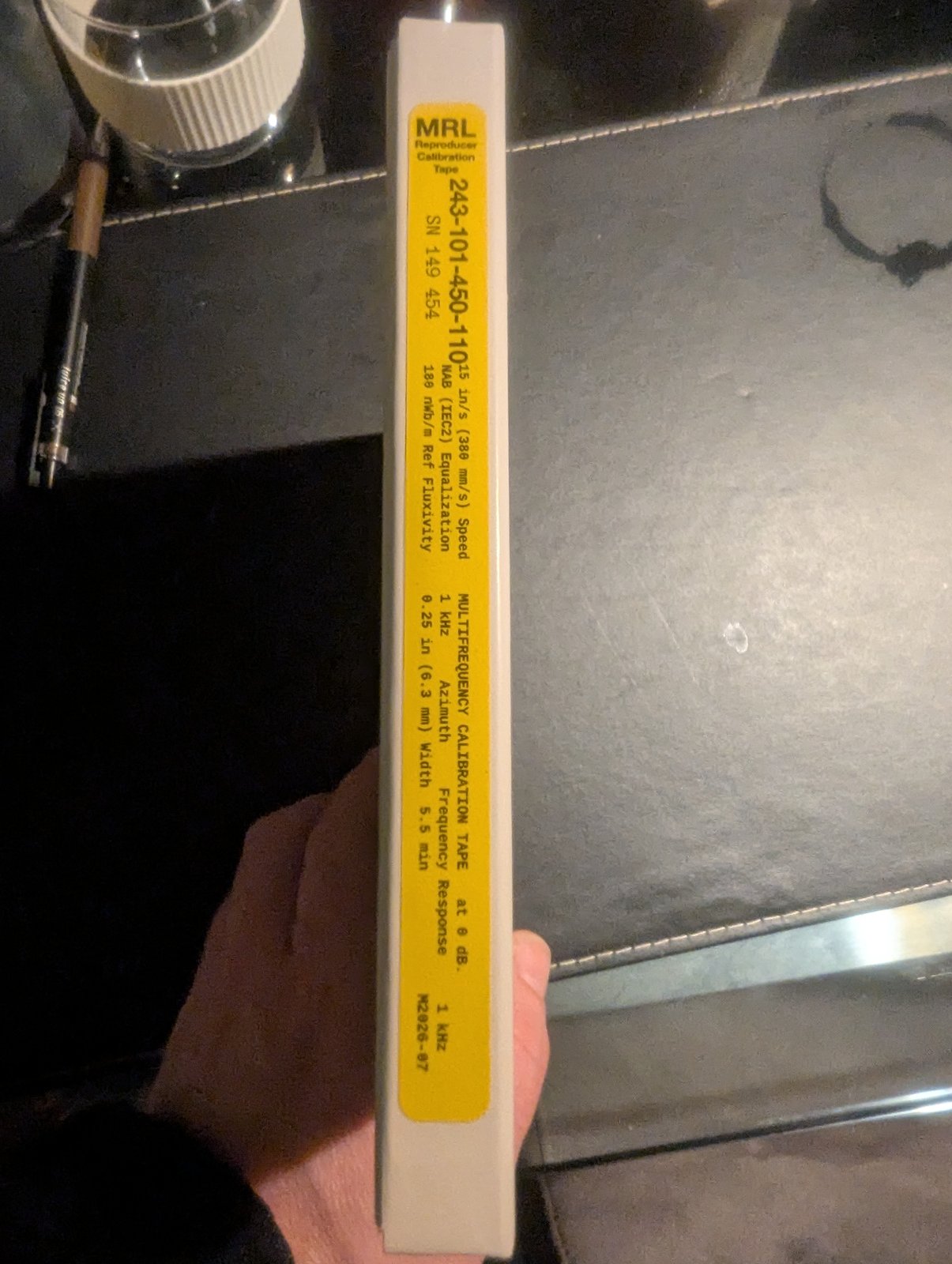
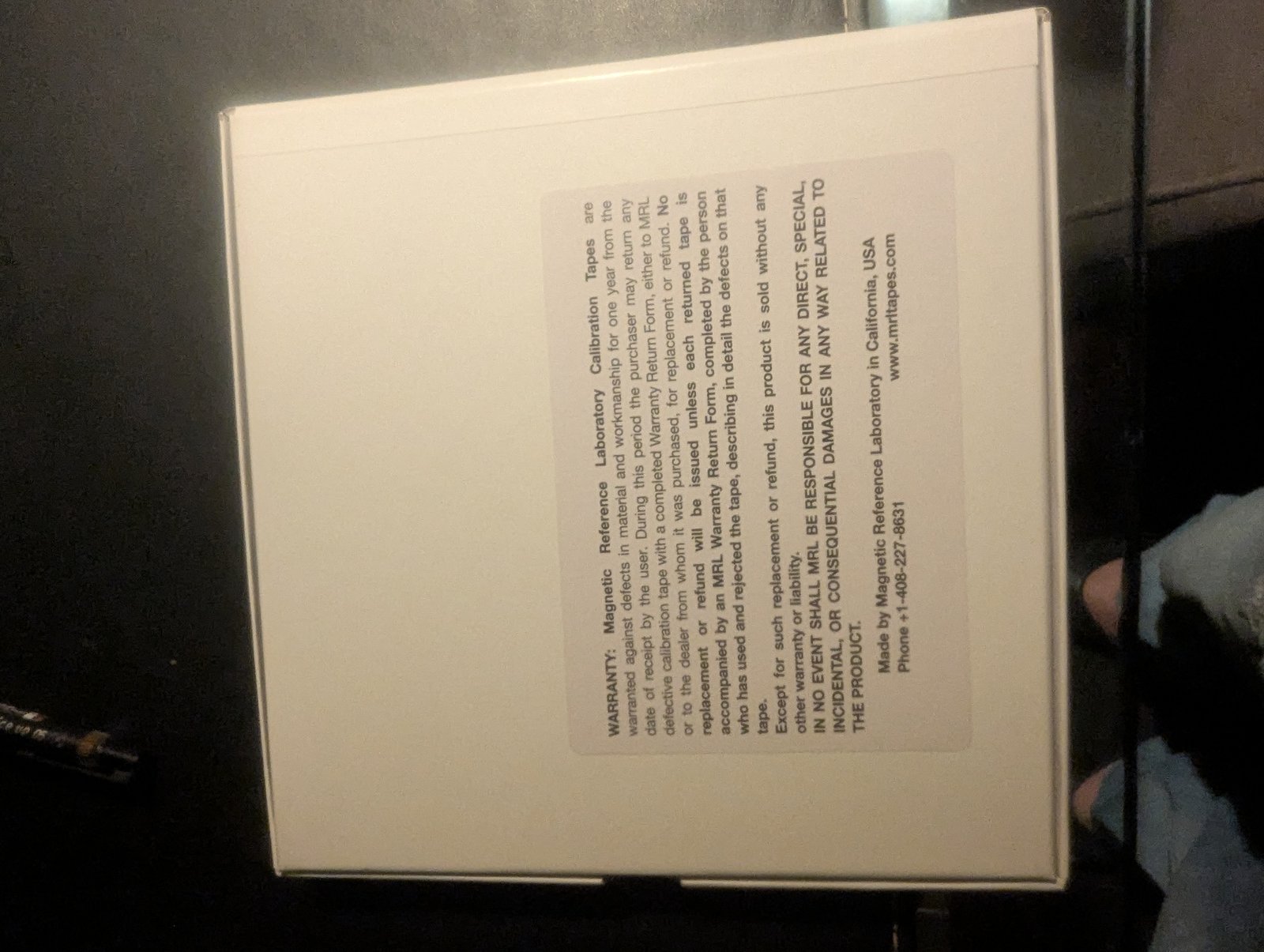
The MRL multifrequency calibration tape, sealed on its reel — 180 nWb/m at 15 in/s, the manual's own reference level.
The 3150 Hz flutter and speed test tape — four minutes of one steady tone, wound tail out.