Operation manual (OIM-1005E) · Part 4 · scan pages 39-46
Preventive Maintenance and Adjustments
This section provides information for preventive maintenance and adjustment which include routine maintenance and normal mechanical/electronic adjustment procedures should be performed at the recommended times to attain the optimum performance.
For further information on maintenance, such as conversion, modification and usage of optional accessories, we have prepared an optional maintenance manual (Otari Part No. OMM-1003E) separately which is available from Otari.
IV-1. TEST AND MAINTENANCE EQUIPMENT REQUIREMENTS↑ TOP
The test and maintenance equipment listed in Table IV-1 is required for the performing of maintenance procedures. Equivalent equipment can be substituted for the equipment suggested in the table.
Table IV-1. Test and Maintenance Equipment
| Equipment Type | Suggested Model | Used for |
|---|---|---|
| Head Cleaner | Ampex 087-007 | Cleaning heads |
| Isopropyl alcohol | Any (Otari Cleaning Kit Ty-502 contains the above cleaning materials.) | Cleaning tape guides, capstan, and capstan pinch roller. |
| Head demagnetizer | Any | Demagnetizing heads and tape guides |
| Lubricating oil | Ampex 087-579 Mobil DTE Oilite | Lubricating capstan |
| Reproduce alignment tape | NAB 3¾ ips: Ampex 4690037-01 7½ ips: Ampex 01-31321-01 15 ips: Ampex 01-31311-01 ICE 7½ ips: Ampex 4690014-01 15 ips: Ampex 01-31313-01 | Setting operating standard reference level |
| Audio Oscillator 20 to 20,000 Hz | Hewlett-Packard 204C or 209D | Setting record equalization |
IV-2. PREVENTIVE MAINTENANCE↑ TOP
For optimum performance, cleaning, demagnetizing should be performed after each eight hours of operation and lubrication should be applied at regular recommended times, indicated below.
IV-2-(1) CLEANING↑ TOP
Oxide particles from the magnetic tape tend to collect on components in the tape path and degrade performance of the recorder. The heads and all other components in the tape path must be cleaned after each eight hours of operation, or more frequently if visual inspection indicates cleaning is required. To clean the head assembly, proceed as follows:
- Lift the head cover as illustrated Fig. IV-1.
- Clean each head stack thoroughly with a cotton-tipped applicator dampened with head cleaner.
— CAUTION —
WHEN CLEANING THE HEADS, USE ONLY THE RECOMMENDED SOLVENT (HEAD CLEANER) TO AVOID DAMAGING THE HEADS. KEEP THE HEAD CLEANER OFF PLASTIC FINISHES AND THE CAPSTAN PINCH ROLLER. DO NOT USE METAL TOOLS THAT CAN SCRATCH THE HEADS.
- Use iso-propyl alcohol to clean all tape-guiding components including the capstan shaft and the rubber capstan pinch roller.
- Reinstall head cover.
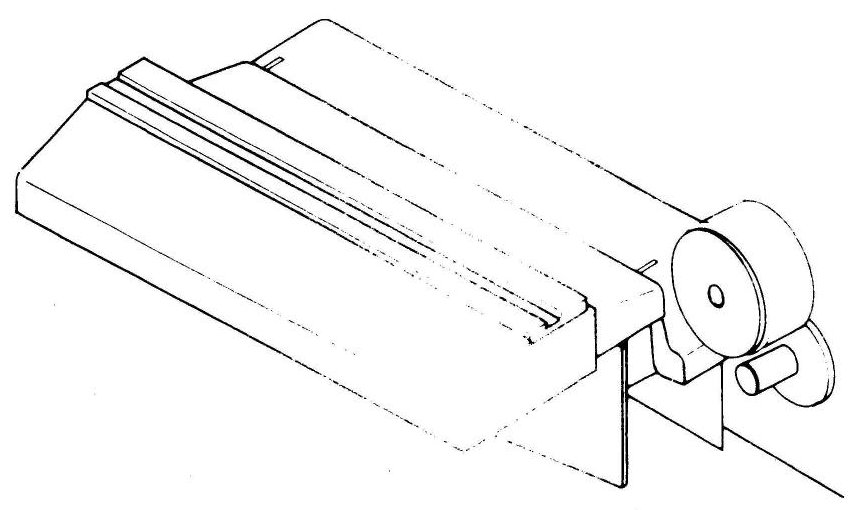 ⤢ zoomLine drawing of a hinged head-cover assembly lifted open on the tape transport, exposing the head stack and guide posts beneath
Fig. IV-1 Lifting Head Cover
IV-2-(2) DEMAGNETIZING↑ TOP
The head and tape guiding components in the tape path should be demagnetized after each eight hours of operation. These components can acquire permanent magnetization that increases signal noise and distortion and partially erase high frequencies on recorded tape. Use a hand-held head demagnetizer to demagnetize all components in the tape path as follows:
- Turn equipment power off and remove any recorded tape near the transport (tape could be partially erased by the demagnetizer).
- Lift head cover as illustrated in Fig. IV-1.
- Cover the demagnetizer tips with adhesive tape to prevent scratching head stacks.
- With the demagnetizer held away from the transport, connect demagnetizer to power souce.
- Move the demagnetizer tips slowly close to the head, lightly touch to the face of one head stack and slowly move the tips up and down the stack several times. Then slowly withdraw the demagnetizer as shown in Fig. IV-2.
- Repeat step 5 for each head stack.
- Repeat the motions of step 5 for each guide and other metallic parts in the tape path.
- Move the demagnetizer slowly away from the transport for at least three feet and then disconnect power from the demagnetizer.
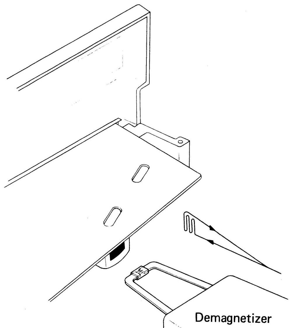 ⤢ zoomLine drawing of a hand-held head demagnetizer being withdrawn slowly from the open head-cover assembly on the tape transport, labeled "Demagnetizer"
Fig. IV-2 Demagnetizing
IV-2-(3) LUBRICATION↑ TOP
The only component requiring lubrication is capstan.
Lubricate capstan every four months, or after each 1,000 hours of operation, (whichever occurs first) using recommended lubricating oil (Table I-4 ), or equivalent. For lubrication, proceed as follow refering to Fig. IV-3:
- Remove pinch roller cap by turning counter clockwise.
- Remove pinch roller from the pinch roller shaft.
- Remove metal dust cap from the capstan shaft by turning counter clockwise.
- Now, the felt collar is visible. Apply 2 or 3 drops of oil onto this felt collar. Please do not overlubricate.
- Wipe off any excess oil and replace the dust cap, pinch roller and pinch roller cap as they were.
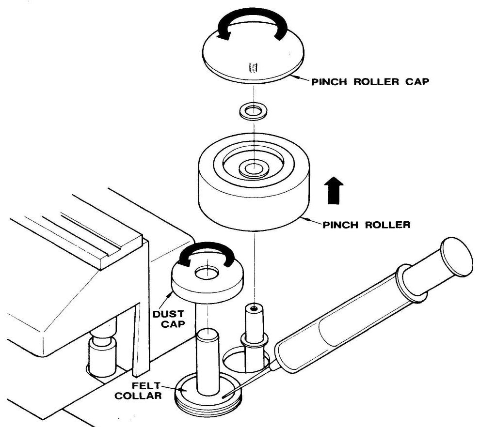 ⤢ zoomExploded diagram of the capstan assembly showing the pinch roller cap, pinch roller, dust cap, and felt collar in disassembly order, with an oil applicator swab shown alongside
Fig. IV-3 Lubrication
— CAUTION —
WHEN THE EQUIPMENT IS FIRST RECEIVED THE CAPSTAN MIGHT HAVE DRIED OUT, EVEN WITH OIL IN THE FELT COLLAR. RUNNING THE CAPSTAN MAY RESULT IN DAMAGE OR FRICTION NOISE BEFORE THE OIL REACHES IT, SO LUBRICATION BEFORE OPERATION MAY BE REQUIRED. SEE FELT COLLAR FIRST.
IV-3. ELECTRONIC ALIGNMENT↑ TOP
Electronic alignment consists of setting the reproduce operating standard-reference-level (SRL), setting record bias level, and setting record equalization. Note that the reproduce adjustment must be performed before making the record adjustments.
The adjustments for these electronics should be performed at regulary scheduled intervals and when changing for one type of recording tape to another.
IV-3-(1) OPERATING STANDARD-REFERENCE-LEVEL ADJUSTMENT↑ TOP
The adjustment is made while playing the operating level on the standard alignment tape. It is important that this adjustment be accurate since it affects signal-to-noise ratio, distortion, and tape saturation level. On Ampex standard alignment tapes this level is 185 nWb/m and is the first tone on 15 ips tapes, and the last tone on 7½ and 3¾ ips tapes. It is suggested that the operating SRL level be set at the speed at which the equipment will usually be used. If used equally, set at 15 ips on high speed model (15 - 7½ ips systems) and at 7½ ips on low speed model (7½ - 3¾ ips systems).
To set operating SRL level proceed as follows:
- Set LINE OUTPUT LEVEL selector switch (Index No.7 of Table II-1) to the desired output standard reference level (+4 dBm or −10 dBm).
- Set SRL calibration switch (Index No.4 of Table III-2) to SRL position.
- Reproduce the 185 nWb/m operating level tone and adjust the SRL/CAL adjustment control for all channels for a 0 reading on the VU meter.
IV-3-(2) BIAS LEVEL ADJUSTMENT↑ TOP
Biasing should be done with the type of tape and at the speed most commonly used for optimum performance. To set bias level, perform the following procedure for each channel.
- Thread bulk arased tape onto the recorder.
- Set SRL calibration switch to calibrate position. Set SPEED switch to "HI" position. Set MONITOR switch to "TAPE" position.
- Start the tape in record mode.
- Press the TEST OSC pushbutton and set the record level control for an on scale reading on the VU meter.
- Adjust the BIAS/CAL adjustment for maximum reading on the VU meter.
IV-3-(3) RECORD EQUALIZATION ADJUSTMENT↑ TOP
Set record equalization for each speed and each channel as follows:
- Thread bulk erased tape onto the recorder.
- Connect a audio oscillator to the INPUT of the recorder and set frequency to 700 Hz.
- Set SRL switch to SRL position.
- Start the tape in record mode.
- For 15 ips tape speed, adjust record level so VU meter indicates 0 VU. For 3¾ or 7½ ips tape speed, set record level so the VU meter is at the −10 VU. Then set SRL switch to normal position and adjust OUTPUT level control so the VU meter indicates 0 VU.
- Change the audio oscillator output to 10 kHz.
- As a preliminary setting, adjust the appropriate low or high speed equalizer so that the VU meter indicates 0.
- Check the response above and below 7 kHz and trim the record equalizer for the response desired.