QXD Instruction Manual — Digital Edition · Part 3 · scan pages 20-29
Operation
This section of manual provides a description of all operating controls and indicators and their use in operating the system in its various modes.
3-1. CONTROLS AND INDICATORS↑ TOP
Table 3-1 shows the location and function of each control and indicator on the tape transport and control panel.
Table 3-1. Tape Transport Controls and Indicators
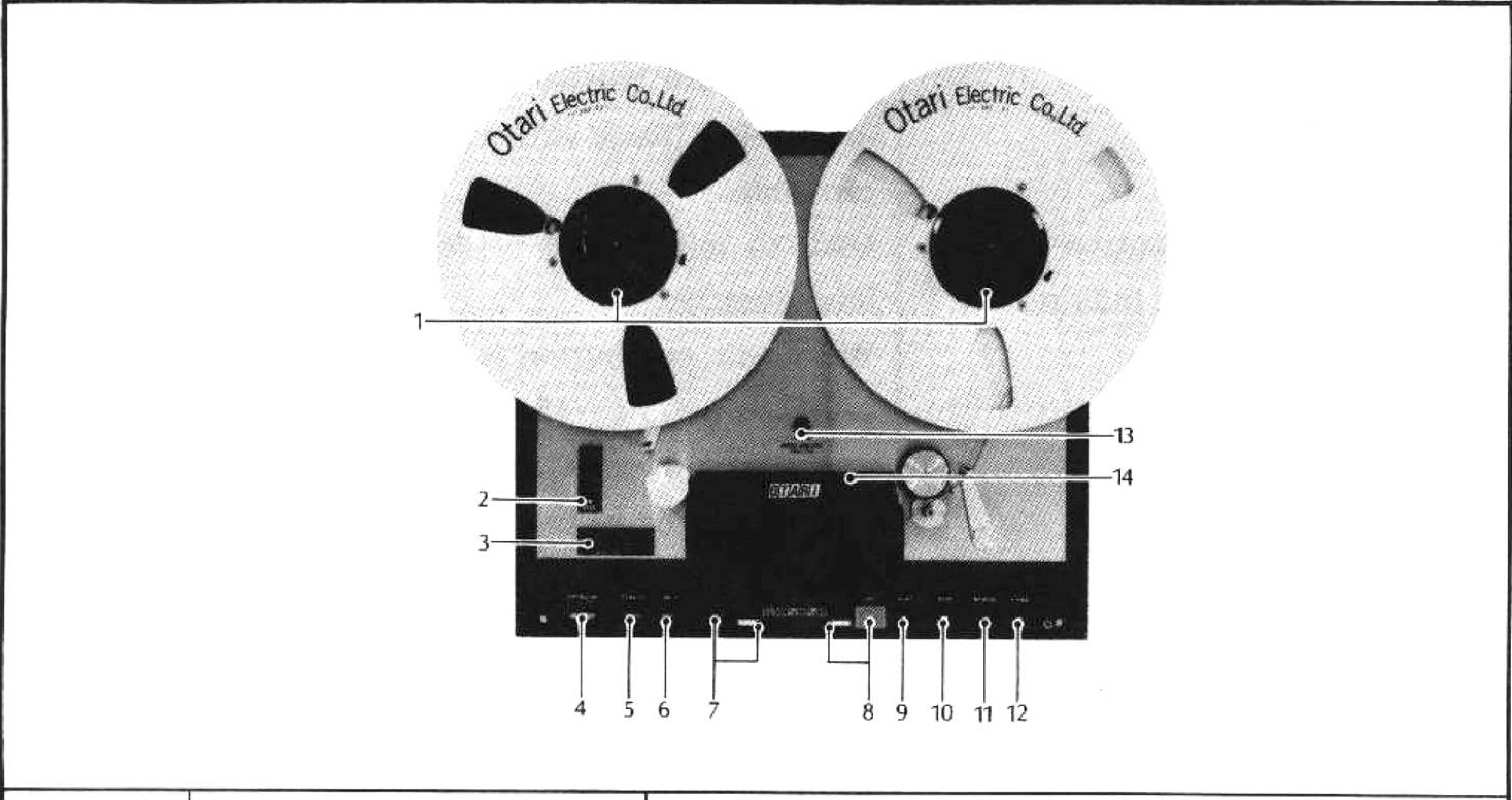 ⤢ zoomTape Transport Controls and Indicators: the tape transport's twin reel turntables and pushbutton control panel, with fourteen numbered callouts keying the index table below
| Index No. | Name | Function |
|---|---|---|
| 1. | NAB Hub Reel Hold Down Knobs | Used to attach reel to reel table by turning knob clockwise. |
| 2. | CUE Lever | In up position, system operates normally. In fast forward and rewind modes, moving lever downward enables variable control of tape lifters to permit audio monitoring. Lever locks in full down position. |
| 3. | Tape Timer | Two-digits in minutes and two-digits in seconds, at real time in 7½ tape speed. Used to locate or log program material on tape. Pushbutton resets time "0". |
| 4. | POWER Pushbutton Switch | In depressed position, power is applied to entire equipment and VU meter illuminates. |
| 5. | SPEED Select Pushbutton Switch | Alternate action pushbutton switch used to select operating speed. On low speed models, push button to in or LO position for 3¾ in/sec and to out or HI position for 7½ in/sec operation. On high speed models, push button to in or LO position for 7½ in/sec and to out or HI position for 15 in/sec operation. |
| 6. | REEL Select Pushbutton Switch | Alternate action pushbutton switch used to select supply and takeup-reel tension for large or small reel-diameter hubs. Push button to in or S position for reels 7 inches or less. Push button to out or L position for 10½ inch reels. (Same size reels should be used on both turntables.) |
| 7. | EDIT Pushbutton Switch and Indicator | Used to initiate edit mode for aid in cutting out unwanted tape. When edit pushbutton is depressed, the green indicator illuminates. Then when PLAY pushbutton is depressed, power is removed from takeup-reel, causing tape to be spilled at takeup side of transport. Other operations are deactivated in edit mode. |
| 8. | RECord Pushbutton Switch and Indicator | Used in conjunction with PLAY and RECORD channel selector. In play mode, when RECord pushbutton is depressed, the red indicator illuminates, and the unit initiates record mode (Called punch in). In record mode, when PLAY pushbutton is depressed, the indicator goes out and the unit deactivates record mode (Called punch out). To prevent pops and clicks when changing between the record mode and other modes, bias current is applied an instant before and is continued for an instant after the other mode is deactivated or activated. |
| 9. | PLAY Pushbutton Switch | Used to select play mode or punch out of record mode. Pressing PLAY pushbutton during fast forward or rewind modes, stops the tape then automatically starts play mode. |
| 10. | STOP Pushbutton Switch | Used to stop tape transport and cancel existing mode of operation. |
| 11. | REWIND Pushbutton Switch | Used to select rewind mode to run the tape from right to left at high speed. Mode may be entered from any other mode except edit mode. |
| 12. | FWD Fast Forward Pushbutton Switch | Used to select fast forward mode to run the tape from left to right at high speed. Mode may be entered from any other mode except edit mode. |
| 13. | PITCH CONTROL Knob | Used to control speed of tape motion. Capstan speed can be controlled within ±7%. When PITCH CONTROL knob is pulled out and turned clockwise, capstan speed rises. When turned counterclockwise, capstan speed falls. In original position, capstan turns with the original speed set by SPEED select pushbutton switch independently of the indicated dial position of the PITCH CONTROL. In record mode, capstan speed is locked automatically to original tape speed and cannot be varied by the pitch control. |
| 14. | Reproduce Head Selector Switch | Used to select ½-track 2 channel or ¼-track 2 channel reproduce head stack to contorm with the kind of tape to be reproduced. (Only applicable for 2SD₂) |
Table 3-2 shows the location and function of each control and indicator on the record/reproduce electronics control panel.
Table 3-2. Record/reproduce Electronics Controls and Indicators
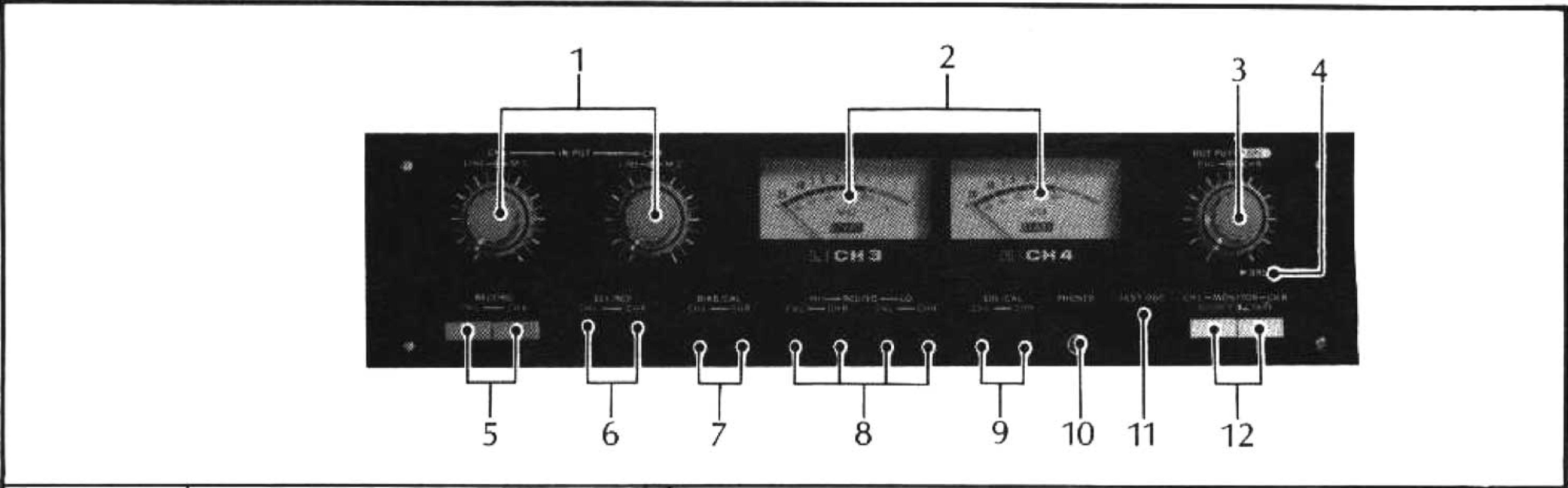 ⤢ zoomRecord/reproduce Electronics Controls and Indicators: the record/reproduce electronics control panel with its LINE MIC and OUTPUT level knobs, two VU meters, and row of adjustment switches, with twelve numbered callouts keying the index table below
| Index No. | Name | Function |
|---|---|---|
| 1. | LINE MIC Level Controls | Used to control recording level input of line (outside knob) and microphone (inside knob) of related channel. Both levels can be mixed. It controls should be placed full counterclockwise when microphone is not used. |
| 2. | VU Meter and Light | Indicates record and reproduce level of related channel depending on mode of operation and position of MONITOR switch. Meter lights when power switch is turned on. |
| 3. | Line OUTPUT level Controls | Used to control output level of related channel. (Control is deactivated when SRL switch is in "on" position.) |
| 4. | SRL Calibration switch and Indicator | Used to fix output level at desired level. Output level is pre-adjusted to specified output level (+4dBm or −10dBm) when SRL of NAB standard tape is reproduced. (At that time VU meter indicates O VU.) Note: If you desire to obtain same output level (+4dBm or −10dBm) in other standard such as CCIR or IEC standard, please refer to Section 4-3-(1). "CAUTION" DO NOT TURN OFF THIS SWITCH UNLESS YOU TURN LINE OUTPUT LEVEL CONTROLS (INDEX NO.3 OF THIS TABLE) DOWN TO THE MINIMUM LEVEL WHILE OUTPUT SIGNAL IS CONNECTED TO OTHER EQUIPMENT TO PREVENT POSSIBLE DAMAGE. |
| 5. | RECORD selector Switch and Indicator | Used to select the desired channel for recording. Used in conjunction with PLAY and RECORD pushbutton switches. Out position prevents activation of the channel record mode to provide a record safe position. Pressing the switch to the In position enables the record mode to be entered and red indicator to be illuminated for that channel. |
| 6. | SEL/REP selector switch and Indicator | In SEL REP (selective reproduction) out position, signal on tape is reproduced normally. In SEL/REP in position, green indicator is illuminated and signal on tape is reproduced by record head (rather than reproduce head) to permit recording on the other channel(s) in synchronism with the channel. Used for overdubbing or sound with sound recording. |
| 7. | BIAS/CAL Adjustment Control | Used to adjust amplitude of bias current of related channel. Used in conjunction with TEST OSC. |
| 8. | REC/EQ Adjustment Control | Used to adjust record equalization of related channel and speed mode (HI or LO). |
| 9. | SRL/CAL Adjustment Control | Used to calibrate to obtain SRL (standard reference level). Used in conjunction with SRL switch and LINE OUTPUT LEVEL selector switch. |
| 10. | PHONES Jack | Receptacle for headphone jack. Used to monitor input or output signal as selected by the MONITOR selector switch Output is −24dBm, unbalanced, and 8 ohm impedance load. |
| 11. | TEST OSC pushbutton switch | When held pressed, a 1kHz test tone is generated and fed to the line input circuit. Used for cue tone recording and in conjunction with BIAS/CAL adjustment. |
| 12. | MONITOR Selector Switch | In out or SOURCE position, input signal is fed to LINE OUT connector, PHONES jack, and VU meter. In the in or Tape position, the reprodused signal is fed to the LINE OUT connector, PHONES jack, and VU meter. |
3-2. OPERATING INFORMATION↑ TOP
3-2-(1) OPERATION of REEL HOLD DOWN KNOB↑ TOP
NAB hub reel hold down knob is operated as follows:
- Turn the knob of the reel hold down knob counterclockwise thus freeing the back.
- Attach the reel hold down knob with the reel to the reel table.
- Turn the knob of the reel hold down knob clockwise and fix the reel hold down knob securely to the reel shaft.
3-2-(2) PRE-OPERATING PROCEDURE↑ TOP
After the equipment has been installed as described in Section 2 of the manual and the operator has become familiar with all the operating controls and indicators described in Table 3-1 and Table 3-2, prepare the recorder for operation as follows:
- Depress POWER switch to the on position. VU meter light will illuminate.
- Place a reel of tape on the supply (left-hand) hub. Note that the reel must turn counterclockwise as tape is pulled off the reel. Place same-size empty reel on the takeup (right-hand) hub (reels of different sizes will cause erratic tape tension and can damage tape). On model MX-5050QXD or 2SD₂, if metal reels are to be used, use a reel adjusting disk (shim) between the reel and the turntable.
- Thread tape as shown in Fig. 3-1 and place the end of the tape in the slot in the empty reel. Wind the reel counterclockwise three to four turns to remove slack and operate the tension arm safety switch.
- Set SPEED selector switch to desired tape speed.
- Set the REEL selector switch to conform to the size of the reel hub diameters being used. Place switch to the out or L position for NAB hubs (10½ inch diameter) or to the in or S position for seven inch plastic reels. On model MX-50502SD₂, set reproduce selector switch to the appropriate position as determined by the track format of tape to be reproduced.
- If desired, connect an 8-ohm headphone or monitor speaker/amplifier to the PHONES jack.
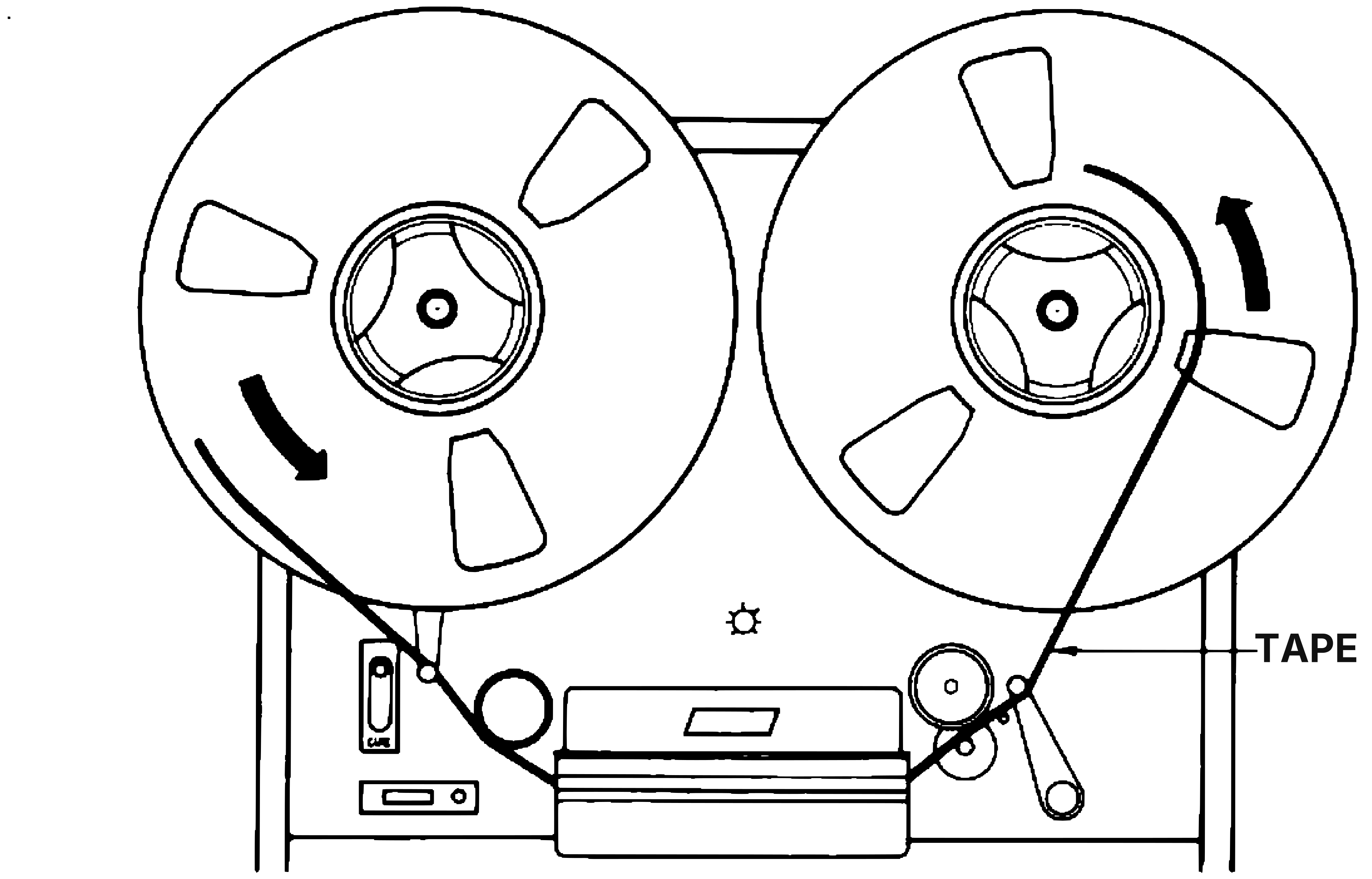 ⤢ zoomFig. 3-1 Tape Threading: the tape path threaded from the supply reel, under the CUE lever and over an idler, past the capstan and pinch roller assembly, to the takeup reel, with the threading path labeled TAPE
Fig. 3-1 Tape Threading
3-2-(3) REPRODUCTION↑ TOP
To reproduce a tape, proceed as follows:
- Perform all steps of the pre-operating procedure.
- Set the channel RECORD selector switch(es) to the out position.
- Set the channel MONITOR selector switches to the TAPE in position.
- Press PLAY pushbutton to begin reproducing of the pre-recorded tape.
- Adjust the channel OUTPUT level control(s) for the desired output level.
- When desired program has been reproduced, press STOP pushbutton to stop tape motion and deactivate play mode.
3-2-(4) RECORDING↑ TOP
To make a recording, proceed as follows:
- Perform all steps of the pre-operating procedure.
- Set the desired RECORD selector switch to the in position for channel(s) selected for recording. The associated red indicator will illuminate to indicate the selected channel(s). Set the switch to the out or record safe position for channel(s) not to be recorded.
- Set the desirable MONITOR select switch to the out SOURCE position.
- Adjust desired INPUT level control(s) so that VU meter indicates O for most audio peaks.
- Push reel-rotation-timer pushbutton to reset timer to O.
- At first, press PLAY pushbutton to start tape motion, then press RECORD pushbutton to start recording on the selected channel(s) (Called punch in). The tape transport RECORD indicator will illuminate.
- While recording, the input signal of each channel can be compared with the reproduced signal of each channel by aternately pressing the MONITOR select switch between the SOURCE and TAPE positions.
- When recording is complete, press PLAY pushbutton for play mode (Called punch out) or press STOP pushbutton to stop tape motion and deactivate record mode.
3-2-(5) RECORDING WITH SELECTIVE REPRODUCTION↑ TOP
The selective reproduction function causes the reproduced audio to be derived from the record head rather than reproduce head. This enables a recording to be made on another channel in time synchronism (in phase) with the channel being reproduced. To record with selective reproduction, proceed as follows:
- Perform all steps of the pre-operating procedures.
- Perform all steps of the Normal Recording procedure for the channel to be pre-recorded.
- Rewind the tape to the point where the selective reproduction is to start.
- Set the selective reproduction (SEL/REP) switch to the in position corresponding to the channel to be monitored while the recording is being made.
- Set the RECORD selector switch to the in position corresponding to the channel to be recorded.
- Set the MONITOR selector switch to out or TAPE position corresponding to the channel being monitored.
- Set the MONITOR selector switch to in or SOURCE position corresponding to the channel to be recorded.
- Adjust the INPUT level control so that VU meter indicates 0 for most audio peaks.
- At first, press PLAY pushbutton to start tape motion, then press RECORD pushbutton to start recording on the selected channel(s).
- When recording is complete, press PLAY pushbutton for play mode or press STOP pushbutton to stop tape motion and deactivate record mode.
3-2-(6) FAST WINDING↑ TOP
For fast-winding operations, and for editing or cueing, press the F.FWD or REWIND pushbutton as desired. These pushbuttons can be pressed alternately without having to press STOP between fast-winding operations. Fast modes may be entered from any other mode except edit mode. Pressing PLAY during a fast-winding mode causes the tape to automatically come to a stop and then enter play mode.
In a fast-winding mode, tape lifters are automatically actuated to lift the tape away from the heads. To monitor the tape in a fast-winding mode, the position of the tape lifters can be varied by operation of the CUE lever. Thus the distance of the tape from the heads may be varied to control the signal level from the tape.
3-2-(7) EDITING AND SPLICING TAPE↑ TOP
For editing and splicing operation, the CUE lever can be used in fast-winding modes to quickly locate desired program material. In addition, there is a EDIT mode of operation to aid in cutting out unwanted tape. When EDIT pushbutton is depressed, the green indicator illuminates. Then the PLAY pushbutton is activate which removes power to the takeup reel, causing tape to be spilled at takeup side of the transport. Other operating modes are deactivated when in the edit mode.
On model MX-5050QXD or 2SD₂, a tape-splicing block (Fig. 3-2) mounted on the head cover can be used to hold the tape for ease of cutting the tape with a single-edge razor blade and application of splicing tape.
Use splicing tape 7/32-inch wide (3M Co., No.41). Do not use cellophane tape.
The tape splicing block has the following features:
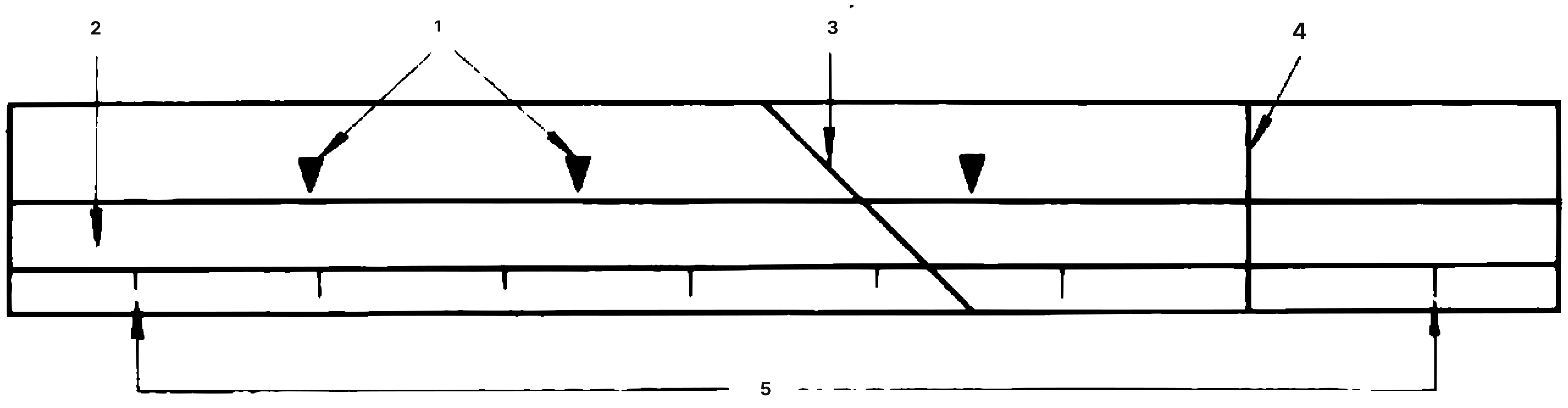 ⤢ zoomFig. 3-2 Tape-splicing Block: the splicing block's tape-guide channel, head-stack indicator marks, 45° and 90° cutting guides, and tape-length calibration marks, numbered 1 through 5 to key the index table below
Fig. 3-2 Tape-splicing Block
| 1. Head-stack indicator marks: | Indicates location of the individual head stacks. |
| 2. Tape-guide channel: | Holds the tape for ease of cutting and splicing. |
| 3. 45° cutting guide: | Used to guide tape cutter for a diagonal cut. |
| 4. 90° cutting guide: | Used to guide tape cutter for a vertical cut. |
| 5. Tape length calibration marks: | Used locate where a plice should be made. |
For exact location of the point for tape cutting during editing, the distance from the right or left hand calibration marks to the 90° cutting guide is the same as the distance from the right or left hand assembly tape guide to the center of the reproduce head.