Synchronizer Interface Information — Digital Edition · Part 2 · scan pages 3-5
MX-5050 MK III Series to BTX Shadow
Three diagrams, one for each kind of MX-5050 MK III series transport: machines with no locator connector, machines with the 16-pin locator connector, and machines with the 34-pin locator connector. The first two include the BQ-II. Each wires the machine to the transport control connector of a BTX Shadow synchronizer.
MACHINES WITH NO LOCATOR CONNECTOR INCLUDING BQ-II↑ TOP
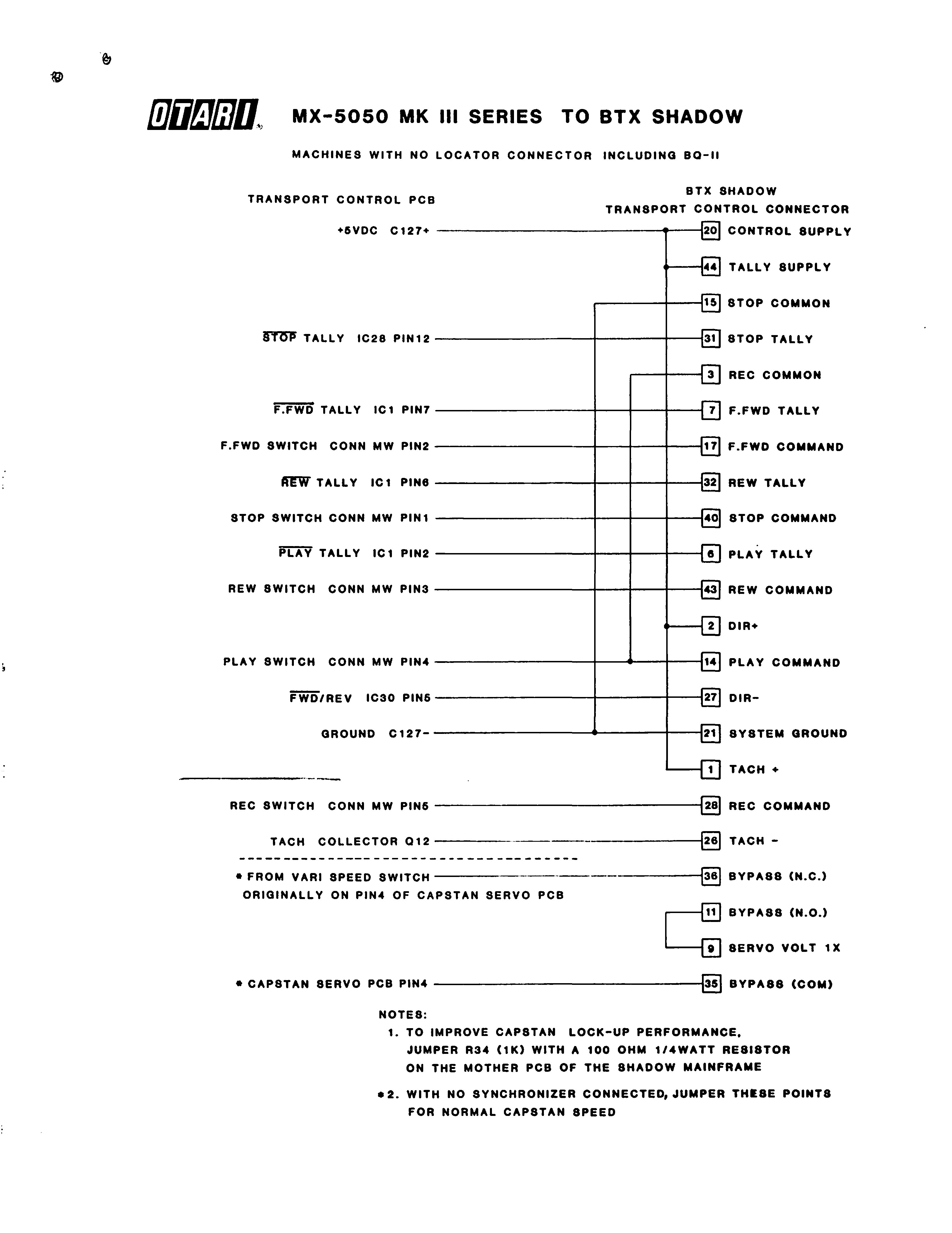 ⤢ zoomMX-5050 MK III Series to BTX Shadow, machines with no locator connector including BQ-II: points on the transport control PCB wired to the BTX Shadow transport control connector, full page scan of page 3
Download the traced vector PDF
| Shadow pin | Shadow signal | Transport control PCB | Joined on the diagram to |
|---|---|---|---|
| 20 | CONTROL SUPPLY | +5VDC C127+ | 44, 2, 1 |
| 44 | TALLY SUPPLY | — | 20, 2, 1 |
| 15 | STOP COMMON | — | 21 |
| 31 | STOP TALLY | STOP TALLY IC28 PIN12 | — |
| 3 | REC COMMON | — | 14 |
| 7 | F.FWD TALLY | F.FWD TALLY IC1 PIN7 | — |
| 17 | F.FWD COMMAND | F.FWD SWITCH CONN MW PIN2 | — |
| 32 | REW TALLY | REW TALLY IC1 PIN6 | — |
| 40 | STOP COMMAND | STOP SWITCH CONN MW PIN1 | — |
| 6 | PLAY TALLY | PLAY TALLY IC1 PIN2 | — |
| 43 | REW COMMAND | REW SWITCH CONN MW PIN3 | — |
| 2 | DIR+ | — | 20, 44, 1 |
| 14 | PLAY COMMAND | PLAY SWITCH CONN MW PIN4 | 3 |
| 27 | DIR- | FWD/REV IC30 PIN5 | — |
| 21 | SYSTEM GROUND | GROUND C127- | 15 |
| 1 | TACH + | — | 20, 44, 2 |
| 28 | REC COMMAND | REC SWITCH CONN MW PIN5 | — |
| 26 | TACH - | TACH COLLECTOR Q12 | — |
| 36 | BYPASS (N.C.) | * FROM VARI SPEED SWITCH ORIGINALLY ON PIN4 OF CAPSTAN SERVO PCB | — |
| 11 | BYPASS (N.O.) | — | 9 |
| 9 | SERVO VOLT 1X | — | 11 |
| 35 | BYPASS (COM) | * CAPSTAN SERVO PCB PIN4 | — |
NOTES:
- TO IMPROVE CAPSTAN LOCK-UP PERFORMANCE, JUMPER R34 (1K) WITH A 100 OHM 1/4WATT RESISTOR ON THE MOTHER PCB OF THE SHADOW MAINFRAME
*2. WITH NO SYNCHRONIZER CONNECTED, JUMPER THESE POINTS FOR NORMAL CAPSTAN SPEED
MACHINES WITH 16 PIN LOCATOR CONNECTOR INCLUDING BQ-II↑ TOP
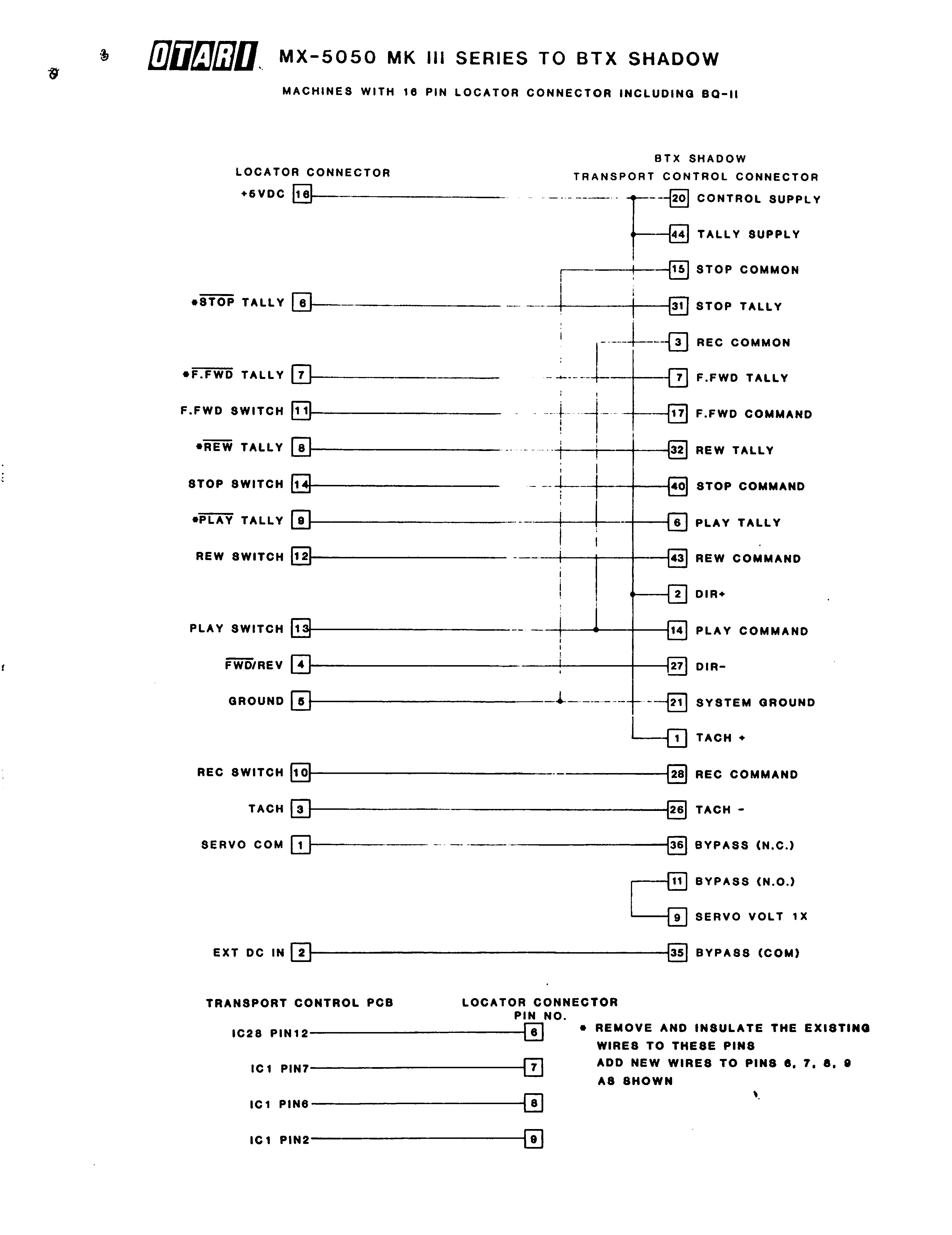 ⤢ zoomMX-5050 MK III Series to BTX Shadow, machines with 16 pin locator connector including BQ-II: locator connector pins wired to the BTX Shadow transport control connector, with four tally wires moved on the transport control PCB, full page scan of page 4
Download the traced vector PDF
| Shadow pin | Shadow signal | Locator connector | Joined on the diagram to |
|---|---|---|---|
| 20 | CONTROL SUPPLY | +5VDC [16] | 44, 2, 1 |
| 44 | TALLY SUPPLY | — | 20, 2, 1 |
| 15 | STOP COMMON | — | 21 |
| 31 | STOP TALLY | *STOP TALLY [6] | — |
| 3 | REC COMMON | — | 14 |
| 7 | F.FWD TALLY | *F.FWD TALLY [7] | — |
| 17 | F.FWD COMMAND | F.FWD SWITCH [11] | — |
| 32 | REW TALLY | *REW TALLY [8] | — |
| 40 | STOP COMMAND | STOP SWITCH [14] | — |
| 6 | PLAY TALLY | *PLAY TALLY [9] | — |
| 43 | REW COMMAND | REW SWITCH [12] | — |
| 2 | DIR+ | — | 20, 44, 1 |
| 14 | PLAY COMMAND | PLAY SWITCH [13] | 3 |
| 27 | DIR- | FWD/REV [4] | — |
| 21 | SYSTEM GROUND | GROUND [5] | 15 |
| 1 | TACH + | — | 20, 44, 2 |
| 28 | REC COMMAND | REC SWITCH [10] | — |
| 26 | TACH - | TACH [3] | — |
| 36 | BYPASS (N.C.) | SERVO COM [1] | — |
| 11 | BYPASS (N.O.) | — | 9 |
| 9 | SERVO VOLT 1X | — | 11 |
| 35 | BYPASS (COM) | EXT DC IN [2] | — |
| TRANSPORT CONTROL PCB | LOCATOR CONNECTOR PIN NO. |
|---|---|
| IC28 PIN12 | 6 |
| IC1 PIN7 | 7 |
| IC1 PIN6 | 8 |
| IC1 PIN2 | 9 |
* REMOVE AND INSULATE THE EXISTING WIRES TO THESE PINS ADD NEW WIRES TO PINS 6, 7, 8, 9 AS SHOWN
MACHINES HAVING 34 PIN LOCATOR CONNECTOR↑ TOP
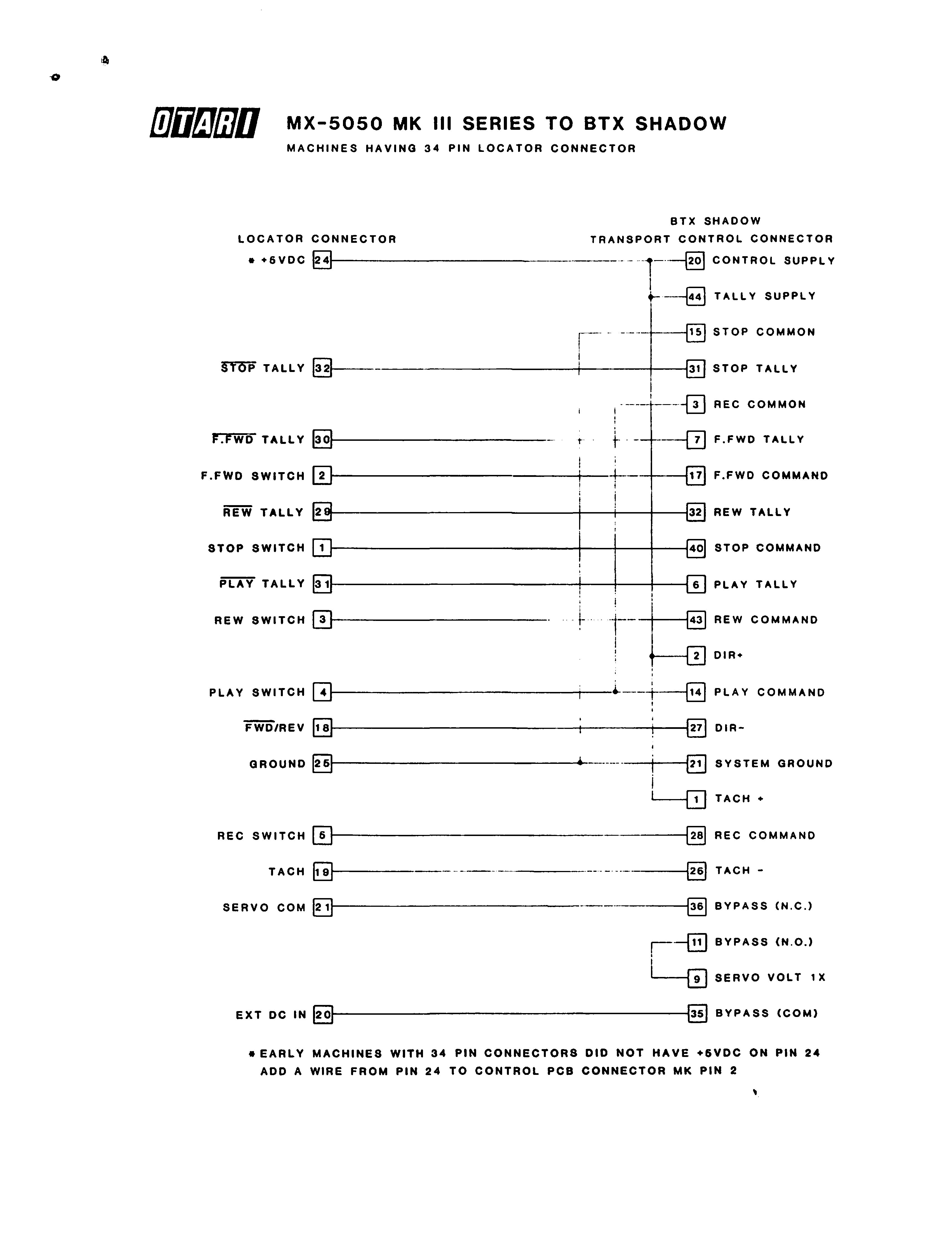 ⤢ zoomMX-5050 MK III Series to BTX Shadow, machines having 34 pin locator connector: locator connector pins wired to the BTX Shadow transport control connector, full page scan of page 5
Download the traced vector PDF
| Shadow pin | Shadow signal | Locator connector | Joined on the diagram to |
|---|---|---|---|
| 20 | CONTROL SUPPLY | * +5VDC [24] | 44, 2, 1 |
| 44 | TALLY SUPPLY | — | 20, 2, 1 |
| 15 | STOP COMMON | — | 21 |
| 31 | STOP TALLY | STOP TALLY [32] | — |
| 3 | REC COMMON | — | 14 |
| 7 | F.FWD TALLY | F.FWD TALLY [30] | — |
| 17 | F.FWD COMMAND | F.FWD SWITCH [2] | — |
| 32 | REW TALLY | REW TALLY [29] | — |
| 40 | STOP COMMAND | STOP SWITCH [1] | — |
| 6 | PLAY TALLY | PLAY TALLY [31] | — |
| 43 | REW COMMAND | REW SWITCH [3] | — |
| 2 | DIR+ | — | 20, 44, 1 |
| 14 | PLAY COMMAND | PLAY SWITCH [4] | 3 |
| 27 | DIR- | FWD/REV [18] | — |
| 21 | SYSTEM GROUND | GROUND [25] | 15 |
| 1 | TACH + | — | 20, 44, 2 |
| 28 | REC COMMAND | REC SWITCH [5] | — |
| 26 | TACH - | TACH [19] | — |
| 36 | BYPASS (N.C.) | SERVO COM [21] | — |
| 11 | BYPASS (N.O.) | — | 9 |
| 9 | SERVO VOLT 1X | — | 11 |
| 35 | BYPASS (COM) | EXT DC IN [20] | — |
* EARLY MACHINES WITH 34 PIN CONNECTORS DID NOT HAVE +5VDC ON PIN 24 ADD A WIRE FROM PIN 24 TO CONTROL PCB CONNECTOR MK PIN 2