Period press · Modern Recording, June 1979 · scan pages 72–74 and 76Review
Otari MX-5050-B Open Reel Tape Recorder
View source PDF ↗Otari MX-5050-B Open Reel Tape Recorder
By John Murphy and Jim Ford
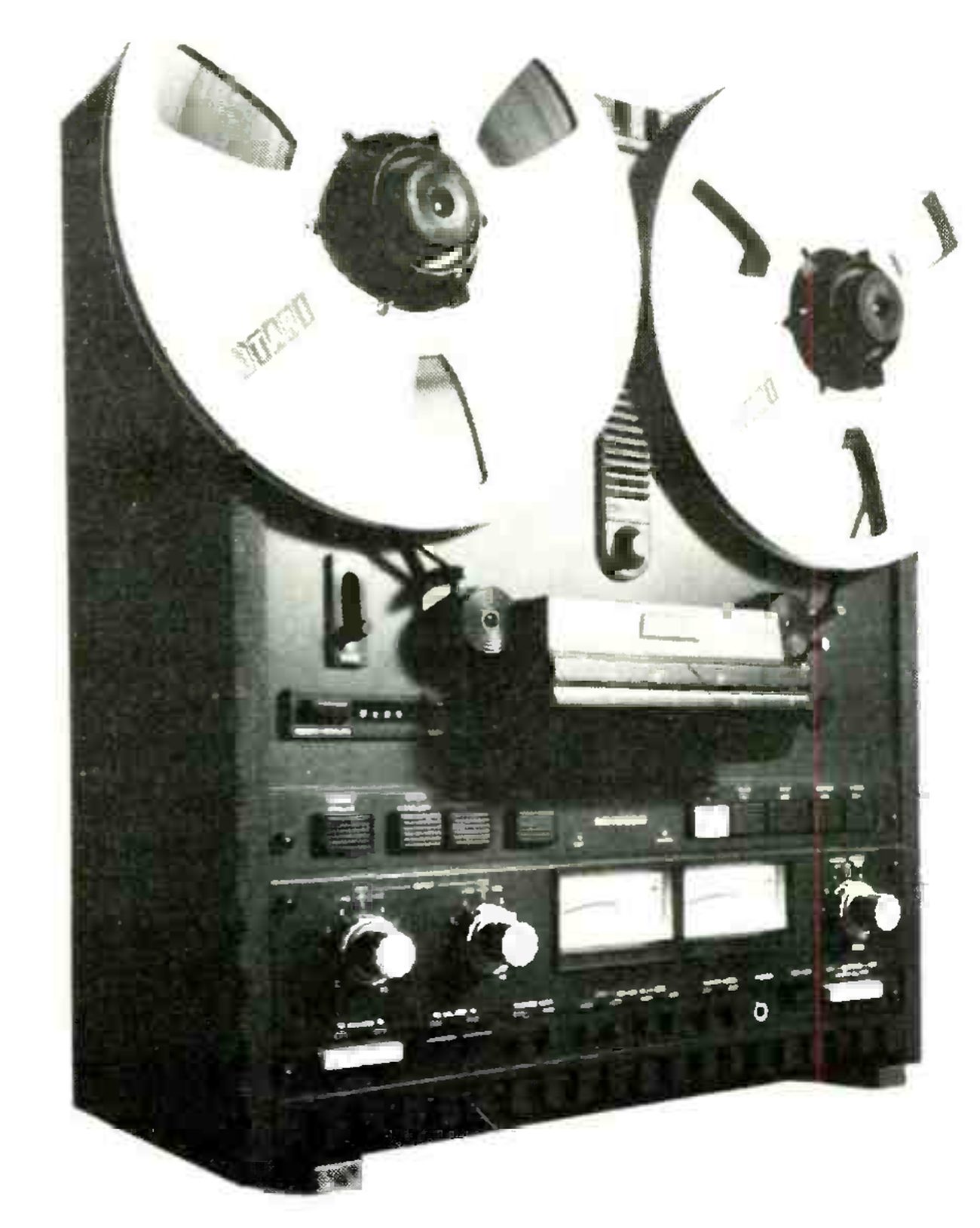 ⤢ zoomThe MX-5050-B photographed from a three-quarter angle with a large Otari reel on each hub, the hinged head cover and splicing block below the reels, the row of push buttons across the transport, and the two VU meters between the input and output level knobs on the electronics panel.
General Description: The Otari MX-5050-B half-track recorder is the successor to the MX-5050 open reel recorder and offers several improvements and new features. Since we had been favorably impressed by the MX-5050 we were eager to check out the new "B" version and see what changes had been made.
Our initial impression was quite positive. Otari has retained the front panel bias, EQ and record level calibration adjustments which made the MX-5050 such an easy machine to set up, and they've added a pitch control, a peak reading LED, a memory rewind and transformer balanced floating outputs.
Editing is easy on this machine because of the edit control and the splicing block right on the front panel. The head cover is hinged to allow easy access to the heads for cleaning or alignment.
The tape transport system utilizes two 6-pole induction motors to drive the reels and a DC servo motor for direct capstan drive. Tape speeds of 15 ips or 7½ ips can be selected by way of a front panel switch. Motion sensing is used in the transport control logic so that the machine can be switched between fast wind modes and play without having to go through stop and without an annoying time delay between modes.
The combination of front panel adjustments and a built-in 1 kHz test oscillator make it rather easy to optimize bias and record level settings for any particular type of recording tape. However, an outboard 10 kHz generator is required to calibrate the record EQ. There is an extra playback head which can be selected for the playback of 4-track tapes.
The front panel layout is very logical making it easy to use the machine, and easy to get excellent results.
The pitch control is located just above the head cover and provides ±7% speed change. It is activated by pulling the control knob out and turning it clockwise or counterclockwise to increase or decrease pitch (tape speed), respectively. When the control is active a red LED next to the knob lights up. When the knob is pressed in, the LED is extinguished to indicate that the transport is operating at the calibrated tape speed. This control may be used during either record or play and is quite useful for synchronizing the pitch of previously recorded music with the pitch of instruments to be recorded on the other track. For example, say track one contains an excellent guitar performance and you want to record a piano part on track two. You set the machine up to monitor the guitar track off the record head (by punching the "sel. rep." button for channel one) so that the piano can be recorded in time synchronization with the guitar. Then you notice that the guitar was tuned flat with respect to the piano (rats!). Normally you would have to either tune the guitar to the piano and then re-record the guitar track (taking a chance on not being able to recreate that inspired performance) or re-tune the piano to the flat guitar. Absurd! However, with a pitch control on the recorder you simply increase the tape speed slightly to bring the flat guitar up to standard pitch and you've salvaged your inspired performance without having to re-tune your piano. What a lifesaver! (And it's much easier to "tune" the recorder than to tune the piano.
Just below the left reel there is an adjustable cue control which defeats the tape lifters during the fast wind modes. This allows the operator to hear the tape and search for selections while fast winding. But be careful. With the lifters fully defeated the output of the machine is loud and can eat your tweeters.
At the bottom of the cue control is a tape counter and memory on-off switch. When engaged, the memory works in conjunction with the counter to stop the transport when the counter passes "0000" in the rewind mode. This feature is very helpful in applications where it is necessary to return to the same tape location many times. At the top of the head cover is a switch allowing for selection of either the 2-track or 4-track playback head.
On the left side of the machine and just below the head cover there is a row of buttons which control (from left to right): POWER (on/off), SPEED (high/low), REEL SIZE (large/small) and EDIT. The machine comes set up for 15/7½ ips operation but can be internally switched over to 7½/3¾ ips operation. The reel size switch is used to select tape tension for either 2¼- or 4½-inch diameter reel hubs. Otari states that the same size reels should be used on both turntables. When the EDIT function is selected, a green LED EDIT indicator to the right of the button lights up. The take-up reel and tension arm switch are defeated and tape is allowed to spill between the capstan and take-up reel. The EDIT mode can be entered from either the play mode or from stop. When in the stop mode, the EDIT button is depressed first, then the PLAY button is pressed. Exact edit points can be located by rocking the reels back and forth. Splicing operations are then facilitated by the built-in splicing block on the head cover. These features make the machine highly suited for production work.
On the right side of the machine just below the head cover are the transport operating controls. From left to right these are: RECORD, PLAY, STOP, REWIND and FAST FORWARD. To the left of the RECORD button is a red LED record indicator. (More about this indicator later.) Below the push buttons on the left side of the machine are the input level controls. There is a pair of concentric mic/line level controls for each channel and mic and line inputs can be mixed if desired. To the right of the input level controls are a pair of VU meters. These are calibrated from −20 to +3 VU and each meter is equipped with a red LED peak indicator. To the right of the VU meters is a pair of concentric output level controls, one control for each channel. Just below these is a slide switch for selecting either "standard reference level" (SRL) output or variable output level. With the switch in the SRL position, the output level controls are defeated and the output is fixed at +4 dBm for a balanced 600-ohm line (when the signal level is at 0 VU). The output level can be reduced to −10 dBm by a rear panel switch to facilitate interfacing with low-level equipment. There is also a record level switch on the back panel for selecting low, medium or high record levels. These represent a 0 VU flux level of 185, 250 and 320 nWb/m, respectively. Otari gives a chart of recommended settings for various types of tapes in the owner's manual. For the low record level setting, 0 VU corresponds to Ampex operating level. The medium and high record level settings are +2.6 dB, and +3.8 dB with respect to the low record level. These are actually record level calibration adjustments to fine tune the machine to various types of tape. (Some types of tape can tolerate higher record levels than others.)
At the bottom of the front panel and to the far left are a pair of red push button switches which separately enable recording in the two channels. Each switch has a red LED just above it which lights whenever recording is possible for that channel. Whenever either channel is ready for recording, the record indicator (next to the RECORD operating control) flashes to indicate that at least one of the channels is prepared. Recording does not begin until at least one channel is prepared and the RECORD button is depressed, along with the PLAY button at the start of tape motion, or after the PLAY mode has been entered if "punch-in" recording is desired. In either case the record indicator changes from the flashing mode to continuous illumination to indicate that recording is in progress. The machine can be taken out of the record mode by either depressing the STOP button, in which case tape motion ceases, or by depressing the PLAY button ("punch-out") in which case recording stops but tape motion continues. Punch-in and punch-out are used for overdubbing in conjunction with the synchronous recording feature.
Just to the right of the record preparatory switches are a pair of switches labeled SEL REP (for "selective reproduce"). By depressing either of these, the user selects synchronous playback of that channel. That is, the tape is played back through the record head of the channel for which SEL REP is selected. This enables the operator to record on the opposite channel in time synchronization with the program monitored through the SEL REP channel. Recording is disabled on any channel for which SEL REP is selected regardless of the position of the record preparatory switch. A green LED lights up above either switch when SEL REP is selected for that channel.
Across the bottom of the machine to the right of the SEL REP switches are small round holes which provide screwdriver access to adjustments for record bias (Ch.1/Ch.2); record EQ (high speed/low speed, Ch.1/Ch.2); and record level (Ch.1/Ch.2). Otari provides excellent instructions in the owner's manual for the proper calibration of these adjustments. To the right of the calibration adjustments is a phone output jack for driving 8-ohm (or higher) headphones. Next to the phone jack is a momentary push button for the test oscillator. When depressed, a 1 kHz test signal is injected into the line input. The level of the signal is controlled by the line input level controls and can then be used to perform bias and record level calibrations. It can also serve as a level calibration tone for other equipment interfaced to the output of the recorder. At the bottom and far right of the front panel are source/tape monitor switches for the two channels. In the out (SOURCE) position the input signal is fed to the outputs and the meters. In the in (TAPE) position the tape playback signal is fed to the outputs and the meters of the machine.
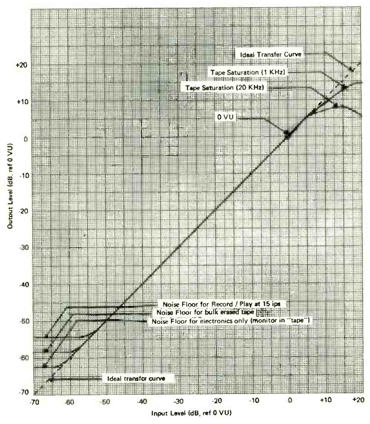 ⤢ zoomA graph of output level against input level, both in dB ref 0 VU from −70 to +20, with the measured transfer curve following the ideal diagonal from the noise floors at lower left to the tape-saturation knees at upper right; labels mark the ideal transfer curve, tape saturation at 1 kHz and 20 kHz, 0 VU, and the noise floors for record/play at 15 ips, bulk-erased tape and electronics only.
The rear panel has a remote control connector to the far left through which all of the transport operations can be remoted. There is a chassis ground terminal beside this connector and input/output connectors on the right side of the rear panel. Input/output connections are made by way of XLR-type connectors. From left to right these connections are: Line Output (Ch.2/Ch.1); Line Input (Ch.2/Ch.1); and Mic Input (Ch.2/Ch.1) There are four slide switches along the bottom of the back section. The first of these is line output level low/high (−10 dBm/+4 dBm). Just to the right of the output level switch is an equalizer switch for selecting either IEC or NAB equalization. Further to the right is the record level switch for selecting low, medium and high record levels as discussed earlier. In the far right bottom corner is a three-position mic attenuator switch; the three positions are labeled 0 dB, −20 dB and OFF. Otari recommends leaving this switch in the off position when the mic inputs are not in use; this practice will keep any noise from the mic preamps out of the system.
Field Test: We had no problems interfacing the recorder with our reference system. We wanted to give the unit a tough test of audio quality so we chose as our program input a very good direct-to-disc recording with which we were already familiar. It would be quite an accomplishment if the recorder could reproduce such excellent music without audible degradation. We put the disc on our turntable and switched in the recorder. First we kept the recorder's monitor switches in the source position and switched the recorder in and out at our preamp. This allowed us to evaluate the recorder's electronics separately from its tape system. We were careful to set the recorder's line input level controls for the same loudness level with the machine switched in as with it switched out of the system. Listening with our best ears we were hard pressed to detect any sonic differences when the recorder was introduced into the system. However, we did agree that there was something slightly "different" about the low bass with the machine in the system. The change was so slight that we can't really say more than that with confidence. So, the audio quality of the electronic section is quite good.
Next we loaded some Ampex 406 tape on the machine so that we could perform the same listening test on the machine's tape system. (We had previously set the machine up for this tape.) Record levels were adjusted so that the peak indicator just flashed occasionally. We then adjusted the output level controls for the same loudness level when the machine was switched in and out at our preamp. We could then listen to the disc directly through our preamp or, at the touch of a button, introduce the recorder (tape and electronics this time) into the chain with no change in loudness level. This would have been a challenging test for any piece of audio gear. Again, we listened critically for any audible differences when the recorder was switched in. Except for the slight time delay the recorder introduced (time for the tape to travel from record head to play head) we couldn't be sure if we were switching in the recorder or not. It was that good. Even the cymbals (which are usually very difficult for a recorder to reproduce without coloration) sounded the same with the recorder in as with it out. There was still something changing in the low bass when we switched the Otari in but it didn't seem much different from when we listened through the recorder's electronics alone. This constitutes truly first class performance for any piece of audio equipment but especially for a tape machine. The only time it became easy to detect when the recorder was in the system was during quiet parts in the music and between cuts on the disc when the tape hiss became audible.
Up to this point we had kept our record levels kind of conservative so we decided to push the levels and see what would happen. We increased the record level enough to make the peak overload indicators flash regularly and peg the VU meter occasionally. Performing the comparison again we noticed a clearly audible degradation in sound quality. We concluded from this that it's best to heed the warning of the peak LEDs and avoid pegging the VU meter. We think it's worth sacrificing a few dBs of signal-to-noise ratio (by using more conservative record levels) to preserve the high audio quality that the 5050-B is capable of.
The machine's controls had a good feel and the LEDs provided good visual indication of the various modes of operation. All of the machine's features performed as expected and there were no surprises. We were really quite impressed.
Lab Test: After getting the recorder on the test bench we calibrated the bias, record EQ and record level (for Ampex 406 tape) according to instructions in the owner's manual. From there we proceeded with the usual tests. The test results can be found in the "Lab Test Summary" section. The record/playback frequency response of this machine is outstanding at either tape speed. The signal-to-noise ratio is strictly tape dependent. Referenced to 3% THD level, the S/N ratio is about 62 dB at 15 ips, and 64 dB at 7½ ips. The dynamic range of the machine can best be seen in the representation of the input/output transfer curve. Distortion is also strongly dependent on the tape used.
The 0 VU distortion level was about half a percent, increasing to about one percent at +3 VU. The three percent distortion level was reached at around +7.5 VU with the peak indicators lighting at +6 VU.
The input and output levels are standard (+4 dBV) and the output level can be reduced to −10 dBV if desired. Thus, interfacing with other pro and semi-pro equipment should pose no problems.
Although Otari states that either high or low impedance mics can be used with the machine, we recommend that low impedance mics be used with an in-line transformer to provide a high impedance input to the machine. Using a typical low impedance mic (Shure SM58) directly into the unit and talking about six inches from the mic we found that the mic preamp noise was only about 33 dB below 0 VU. Using an in-line high impedance transformer this figure improved to 47 dB. A recorder of this caliber deserves to be used with a high quality mic mixer in order to take full advantage of the machine's capabilities.
Serviceability of the unit looks pretty good as there is good access to the circuit boards.
Otari provides an excellent owner's manual with detailed explanation of the various operating modes and features of the machine.
Conclusion: The MX-5050-B is a truly excellent half-track tape recorder. The new features, such as pitch control and memory rewind make it even more flexible than the previous version. It is well suited to production work and can do synchronous recording. We give it our highest recommendation. Good work, Otari!
LAB TEST SUMMARY
(Note: All dBV values are referenced to .775V)
Frequency Response for Playback Only
15 ips tape speed
- Two-track head: (Ch. 1) ±1.2 dB 30-15 kHz; (Ch. 2) ±1.4 dB 30-15 kHz
- Four-track head: (Ch. 1) ±1.5 dB 50-15 kHz; (Ch. 2) ±2.0 dB 50-15 kHz
7½ ips tape speed
- Two-track head: (Ch. 1) ±2.6 dB 50-15 kHz; (Ch. 2) ±2.5 dB 50-15 kHz
- Four-track head: (Ch. 1) ±2.5 dB 50-15 kHz; (Ch. 2) ±2.6 dB 50-15 kHz
Playback Through the Record Head (Sel. Rep.)
- 15 ips tape speed: (Ch. 1) ±3 dB 50-15 kHz; (Ch. 2) ±3 dB 50-15 kHz
- 7½ ips tape speed: (Ch. 1) ±3 dB 60-8 kHz; (Ch. 2) ±3 dB 60-8 kHz
Record/Playback Frequency Response
(Note: All tests were made with Ampex 406 tape with the record level switch in the medium position)
- 15 ips tape speed (0 VU record level): Ch. 1: ±1 dB 25-29 kHz; Ch. 2: ±1 dB 26-29 kHz
- 7½ ips tape speed (−10 VU record level): Ch. 1: ±1 dB 20-22 kHz; Ch. 2: ±1 dB 20-22 kHz
Record/Playback Signal-to-Noise Ratio (unweighted)
(Note: All S/N values are referenced to 0 VU)
- 15 ips tape speed (1 kHz test signal): Ch. 1: −54.1 dB; Ch. 2: −54.6 dB
- 7½ ips tape speed (1 kHz test tone): Ch. 1: −56.8 dB; Ch. 2: −56.8 dB
(continued)