Period press · Modern Recording, March 1983 · scan pages 51–60Review
Otari MX-5050-MKIII-8 Professional Reel-to-Reel Recorder
View source PDF ↗Otari MX-5050-MKIII-8 Professional Reel-to-Reel Recorder
General Description: The Otari MX-5050-MKIII-8 recorder is a professional quality, two-speed 8-track tape recorder/reproducer which accommodates ½-inch wide tape and operates at either 15 or 7½ ips. Among its many professional features are: selective reproduction (SEL/REP), automatic motion sensing control, an edit control that permits tape spilling, dynamic braking, an electronic real-time tape counter, an adjustable cueing control for audible monitoring in fast-forward and rewind, a dual-frequency test and cue-tone oscillator, adjustable bias, equalization and level controls, XLR connectors for line inputs and line outputs, standby mode for ease of multi-channel recording, remote controllable electronics, a VU meter with peak indicator for each channel, selecting switches for input and output levels, and a memory stop for automatically stopping the tape at a desired point during playback.
The tape transport design used in the MX-5050-MK111-8 uses two 6-pole induction motors for the tape reels and a direct-drive DC servo motor for the capstan. A pitch control is available for adjusting tape speed over a 7 percent range. In addition to the editing controls, a tape splicing block is mounted on the head cover for easy editing, cutting and tape splicing. Momentary-contact pushbutton switches on the transport are used to select record, play, stop, rewind, fast forward, and edit modes. All of these modes except the edit function can be controlled by an optionally available remote control unit, Model CB-110.
There are several other operating features worth mentioning. Available sound applications include overdubbing of sound with sound, sound on sound, etc., which can be carried out by the punch-in and punch-out functions of the transport controls. In addition to bias, level, and equalization—which can be optimally adjusted for each channel by means of rear-panel screwdriver controls—low frequency compensation controls are also provided for accurate adjustment and alignment of low-frequency characteristics to correspond with the particular tape being used. In order to make multi-channel recording even easier, the monitor programs of record-ready channels are automatically switched to input during fast-forward, rewind, or stop modes. This function can be selected with the standby switch on the rear panel. The Otari MX-5050-MKIII-8 is designed to operate on a table top, with reels oriented horizontally rather than vertically. The eight VU meters are conveniently positioned on a raised header at the rear of the instrument, placing the meters at eye level for easy viewing.
Controls and Switches: The rear panel of the recorder is equipped with two-position input and output level switches for each channel. These select -8 dBm or +4 dBm levels. XLR input and output connectors, a ground terminal, the remote control connector and a power line cord socket are also located on the rear panel, as are eight banks of fourteen small holes per channel, arranged in vertical rows. These provide access to screwdriver controls for adjusting such important operating parameters as peak level meter settings, VU meter levels, repro level, low frequency compensation, high and low frequency playback EQ, SEL/REP level, input level, record level, high and low frequency record EQ, input SRL (Standard Reference Level), internal oscillator level and, of course, record bias level. Of all these adjustments, those having to do with the tape used were factory set for Scotch 226 tape and therefore all of the definitive tests and measurements made on our sample were done using that type of 3M ½-inch tape.
The front and top surfaces of this tape recorder are also loaded with controls and useful features. In addition to incorporating the light-touch transport controls already listed, the top surface houses the power on/off switch, speed selector and reel-size selector buttons, the variable pitch control, the edit switch, memory and counter reset switches and the real-time digital tape indicator which displays elapsed time (negative as well as positive) in hours, minutes and seconds. The header-like back panel at the rear of the instrument houses the eight VU meters (each with its peak-flashing LED), individual channel input level controls, and individual SRL pushbutton switches which bypass the channel level control and select the internally preset input level. When inputting reference level, the VU meter will indicate 0 VU while rated output level will appear at the line output terminals.
Remaining controls and switches are found on the forward front panel of the deck. There are individual ready/safe switches for each channel, individual switches that select input, SEL/REP or "repro" (tape playback) to be fed to the line outputs, a phone jack and phone level control, individual channel buttons which determine which outputs shall be fed to the phone jack, a test oscillator selector switch, and an external oscillator connection jack. A vertically-oriented bank of five more pushbutton switches takes care of such additional functions as selecting external remote control; sending all input signals to the line-out connectors, phone jacks, VU meters and peak indicators; activating the SEL/REP function for all channels at once; sending the signals picked up by all channels of the reproduce head to the line-out connectors, phone jack, VU meters and peak indicators and, finally, permitting individual channels of input, SEL/REP or repro to be selected by the monitor selection toggle switches already mentioned.
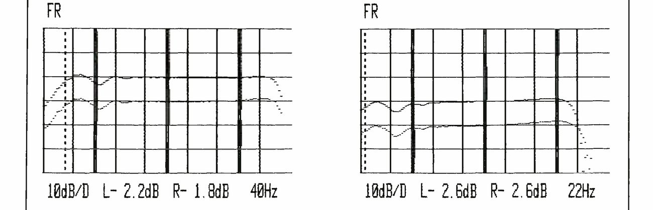 ⤢ zoomTwo frequency-response plots from the test set, side by side, the 15 ips plot (A) at left and the 7½ ips plot (B) at right (the letters themselves are outside the crop), each labelled FR at top left, with the record/play curves running flat across a grid of 10 dB per division and a dotted cursor line near the low-frequency end; the readouts beneath read 10dB/D L- 2.2dB R- 1.8dB 40Hz under (A) and 10dB/D L- 2.6dB R- 2.6dB 22Hz under (B).
Fig. 1: Otari MX-5050-MKIII-8: Frequency Response Plots at 15 ips (A) and 7½ ips (B) using Scotch 226 tape. Cursor is set to show approximately -2 dB low frequency cut-off point.
Fig. 2: Otari MX-5050-MKIII-8: Same as Fig. 1, except cursor is set to show approximately -2 dB cut-off point at high frequency end of plots.
Test Results: For all its sophistication and elaborate number of controls, the purpose of this or any other multi-track tape recorder is to make high-quality studio recordings effectively. Our laboratory performance tests were designed to show how well it accomplishes this fundamental task on a technical level. Elsewhere in this issue, you will find a hands-on evaluation of how effectively the Otari MX-5050-MKIII-8 does its job in an actual studio environment.
As mentioned earlier, the owner's manual supplied with the Otari deck recommends the use of Scotch 226 tape, and this is used at the factory to calibrate this machine. Since we wanted to see just how accurately that calibration had been done, we decided not to touch any of those rear panel controls at all, but simply to use Scotch 226 tape and let the measurements fall where they would. Before detailing the specific results, we must say that we were delighted with the accuracy of alignment that had been done by the people at Otari. As calibrated, Scotch 226 and the Otari MX-5050-MKIII-8 were "made for each other."
The most significant measured results of our lab tests are summarized in our usual VITAL STATISTICS table at the conclusion of this report. Figure 1 shows plots of record/play frequency response for both operating speeds. In Figures 1A and B, record levels were at 0 VU (which in this case corresponds to a magnetization level of 250 nWb/m) and -10 dB). At both speeds a fair amount of head-contour effect is noted at the low end, but if we disregard this, response extends down to 40 Hz at 15 ips (for a -2 dB roll-off), and down to around 22 Hz at the slower tape speed.
Figures 2A and B are identical to the plots of Figures 1A and B except that the dotted-line "cursor" has been moved over to show the high-frequency at which roll-off begins. Note that at the higher tape speed, high end extends to almost the same frequency at the 0 dB level as it does for the -10 dB record level. At the lower speed, however, response is down 11.4 dB at 21 kHz for the "0 dB level" plot (designated as "L"), while it is only down 2.1 dB at that frequency for the -10 dB record level test.
Fig. 3: Otari MX-5050-MKIII-8: Third order distortion vs. record level using Scotch 226 tape at 15 ips (A) and 7½ ips (B). Cursor is set to 0 VU (250 nWb/m) in each case (see text).
Figure 3 illustrates a plot of third-order distortion versus record level, but before examining the results, a word of explanation is in order. Normally, our Sound Technology Tape Recorder Test Set automatically begins plotting this test at a +10 dB level (referred to the 0 dB reference level which we always set at the beginning of any test series). In the case of this Otari deck, +10 dB was not a high enough level to cause a 3 percent third-order distortion (the headroom is that good). As a result, we had to deliberately increase our input signal level by about 4 dB. Thus, the double vertical line which normally corresponds to a 0 dB reference level is actually at +4 dB in the graphs of Figures 3 and 4. For this reason, to read actual 0 VU third-order distortion, we moved the cursor on the graph to the -4 dB point and read 0.27 percent at 15 ips and 0.21 percent third-order distortion at the 7½ ips speed.
Similarly, in Figure 4, when we read a +9 dB in Figure 4A and a +8 dB in Figure 4B for the record level required to produce approximately 3 percent third-order distortion during playback, we really have to add 4 dB to those readings. Thus, headroom (or mid-frequency MOL) at 15 ips was actually +13 dB (9 dB plus the extra 4 dB by which we increased reference level above 0 VU), while at 7½ ips it was 12 dB. Both of these figures correspond nicely with the levels at which the peak indicators on the VU meters have been set to flash. For the signal-to-noise analyses which are represented graphically in Figures 5 and 6, we further increased the test set reference levels to these higher record levels (+13 and +12 dB) so that the S/N readings would be referenced to approximately 1040 nWb/m, or the 3 percent third-order distortion points, in accordance with common practice.
Fig. 4: Otari MX-5050-MKIII-8: Same as Fig. 3, except cursor set to read level at which 3rd order distortion is approximately 3%. Add 4 dB to readings shown to obtain max. Record level re: 250 nWb/m.
Fig. 5: Otari MX-5050-MKIII-8: S/N analysis (unweighted) at 15 ips (A) and 7½ ips (B), using Scotch 226 tape.
On the basis of that reference level, unweighted S/N at the 15 ips speed measured 70.6 dB, while for the 7½ ips speed the result was a S/N of 68.5 dB. Both figures were substantially better than those claimed by Otari in their published specs (see Figures 5A and B). The same held true when we used NAB weighting. Under those conditions, as shown in Figure 6, we obtained a S/N reading of 75.8 dB at the higher tape speed, and 72.7 dB at the 7½ ips speed.
Fig. 6: Otari MX-5050-MKIII-8: Signal-to-noise analysis as in Fig. 5, except using NAB weighting curve.
Figures 7A and B represent linearity, or input versus output plots at two frequencies: 315 Hz and 15 kHz in the case of Figure 7A; 315 Hz and 10 kHz in the case of Figure 7B. In Figure 7A, mid-frequency linearity was very nearly perfect all the way out to +10 dB record level (9.7 dB output during playback for a +10 dB input). At that high speed, linearity for a 15 kHz signal was also amazingly good, showing only a slight degree of tape saturation at the +10 dB record level (7.3 dB output of the 15 kHz signal during playback for a +10 dB record level input).
As you might expect, results were not anywhere near as good when tape speed was reduced to 7½ ips. In fact, we had to lower the high-frequency test signal to get a meaningful reading. In Figure 7B, we see that mid-frequency (315 Hz) is as good as, if not better than, it was at the higher tape speed, but now even a 10 kHz high-frequency signal is fast approaching saturation when the record level is increased to a +10 dB. Output now reads 5.9 dB for an input level of +10 dB, or a non-linearity of 4.1 dB.
Fig. 7: Otari MX-5050-MKIII-8: Linearity (MOL) analysis at 15 ips, using test signals at 315 Hz (A) and at 7½ ips using test signals at 315 Hz and 10 kHz (B). Reference tape used was Scotch 226.
 ⤢ zoomTwo wow-and-flutter analyses from the test set, side by side, each a spectrum of flutter components with a single tall bar in a separate panel at right: (A) reads FL WD L0.020% FS0.030% at top and .010%/D L+0.019% 16.0 Hz beneath; (B) reads FL WD L0.066% FS0.10% at top and .010%/D L+0.065% 8.00 Hz beneath.
Fig. 8: Otari MX-5050-MKIII-8: Wow-and-flutter analysis, NAB weighting at 15 ips (A) and 7½ (B).
The graphs of Figure 8 are analyses of wow-and-flutter at the two operating tape speeds. This type of graphic analysis is extremely useful in pinpointing specific tape transport problems that cause wow-and-flutter. In Figure 8A we see that total NAB-weighted wow-and-flutter measured a very fine 0.02 percent. However, notice that the major component of this wow-and-flutter occurs at a most unusual frequency of 16 Hz (the graph plots from 200 Hz down to 0.5 Hz). This is most atypical, and possibly suggests that some moving part that is rotating at around 960 rpm is slightly deformed. Perhaps this may even have occurred in shipment. Note that the contribution of this one flutter component is 0.019 percent (the number at the bottom of the graph) or almost the entire total, which is only slightly higher, at 0.020 percent.
Confirmation of this deformity somewhere in the tape transport system of this recorder was obtained when we repeated the measurement of wow-and-flutter at the 7½ ips tape speed. Now the chief offending frequency of wow occurred at 8 Hz, exactly half of 16 Hz. Note, too, that the contribution of this offending frequency again almost equals the total wow-and-flutter reading: 0.065 percent as against 0.066 percent. We suspect that if this problem had not been found in this deck, the wow-and-flutter figures would certainly have been lower for the 7½ ips speed and might even have been a bit lower for the already excellent figure obtained at the higher tape speed.
Fig. 9: Otari MX-5050-MKIII-8: When Scotch 250 tape is used with bias set for Scotch 226, high-end rise occurs at both 15 ips (A) and 7½ ips (B) indicating need for higher bias level.
In order to illustrate the importance of proper calibration of this or any other professional tape deck for the tape with which it is to be used, we decided to conduct an additional experiment. We switched to Scotch Type 250 recording tape (in itself, an excellent high-quality tape formulation that many professionals use) and ran a couple of frequency response curves without altering any of the operating parameters (bias, EQ, low-frequency compensation, etc.) of the Otari MX-5050-MKIII-8. The results are shown in the graphs of Figure 9. At the higher tape speed (Figure 9A), deviation from flattest possible response was not too severe, although a slightly rising high end is clearly in evidence. Switching to the slower tape speed, however (Figure 9B), we see a fairly lopsided response curve, with a sharply rising (overly brilliant sounding) high-end and a seriously attenuated low-end that could obviously use readjustment of low-frequency compensation.
If the results in Figure 9 aren't enough to convince you of the importance of matching and calibrating a fine deck such as this Otari MX 5050 MKIII-8 to the tape with which it's to be used, you might want to take a look at Figure 10. Here, we reverted to the recommended Scotch 226 tape once again, but instead of leaving the bias control set where it has been, we rotated it first all the way to one extreme and then to the other, in each case plotting the resulting record/play response curve. Enough said?
Fig. 10: Otari MX-5050-MKIII-8: Offers very wide range of bias adjustment. Here, response curves were plotted for Scotch 250 tape with bias adjusted arbitrarily for minimum and maximum settings.
Individual Comment: As you have surely gathered by now, I was very favorably impressed by both the mechanical and electrical aspects of this excellent 8-track deck. Despite its great number of controls and switches, everything is so logically laid out that it took me only a short time to become thoroughly familiar with the operation of the recorder. The accompanying operating manual is well-written, too, and includes complete trouble-shooting and servicing procedures as well as clear schematic diagrams and board layout diagrams. While I can speak about the measured performance and relative ease of use of the recorder, I defer to Michael Tapes, who put the machine through its paces after I finished my lab evaluation of it. His hands-on report follows.
OTARI MX-5050-MK III-8 REEL-TO-REEL RECORDER: Vital Statistics
| SPECIFICATIONS | MANUFACTURER'S SPECS | LAB MEASUREMENT |
|---|---|---|
| Tape width & tracks | ½-inch/8 tracks | Confirmed |
| Tape Speeds | 15 and 7½ ips | Confirmed |
| Maximum reel size | 10½ inch | Confirmed |
| Heads | 3 8-track in-line | Confirmed |
| Rewind Time (2500′) | 100 seconds | 82 seconds |
| Line Input Level | +4 dBm/-8 dBm, switchable | Confirmed |
| Line Output Level | +4 dBm/-8 dBm, selectable | Confirmed |
| Headphone level | -19 dBm | Confirmed |
| Equalization | NAB or IEC for 7½ & 15 ips | Confirmed |
| Frequency Response (Rec/Play) | ||
| 15 ips | 40 Hz to 25 kHz, +/-2 dB | 40 Hz to 35 kHz |
| 7½ ips | 20 Hz to 20 kHz, +/-2 dB | 22 Hz to 21 kHz |
| Signal-to-Noise Ratio: | ||
| NAB Wtd, 15/7½ ips | 70/70 dB | 75.8/72.7 dB |
| NAB Unweighted, 15/7½ ips | 66/66 dB | 70.6/68.5 dB |
| IEC Weighted, 15/7½ ips | 70/70 dB | N.A./N.A. |
| IEC Unweighted, 15/7½ ips | 66/66 dB | N.A./N.A. |
| Crosstalk | Better than 55 dB | More than 60 dB |
| Wow-and-flutter, NAB W'td, 15/7½ ips | 0.05%/0.06% | 0.02/0.066% |
| Distortion, 1 kHz, at 250 nWb/m | Less than 0.5% | 0.27% |
| Erase Efficiency | Greater than 70 dB | Confirmed |
| Test oscillator frequencies | 1 kHz and 10 kHz | Confirmed |
| Bias and erase frequency | 200 kHz | Confirmed |
| Peak Indicator Level | 1040 nWb/m | 800 nWb/m |
| Dimensions | 17.3″ w. x 26.6″ d. x 17.3″ h. | Confirmed |
| Weight | 77 lbs. | Confirmed |
| Power Requirements | 100, 117, 220, 240 V, 50/60 Hz AC | |
| Power Consumption | 150 watts | 135 watts |
Suggested List Price: $5295.00.
CIRCLE 51 ON READER SERVICE CARD
Otari MX-5050-MKIII-8
Michael Tapes
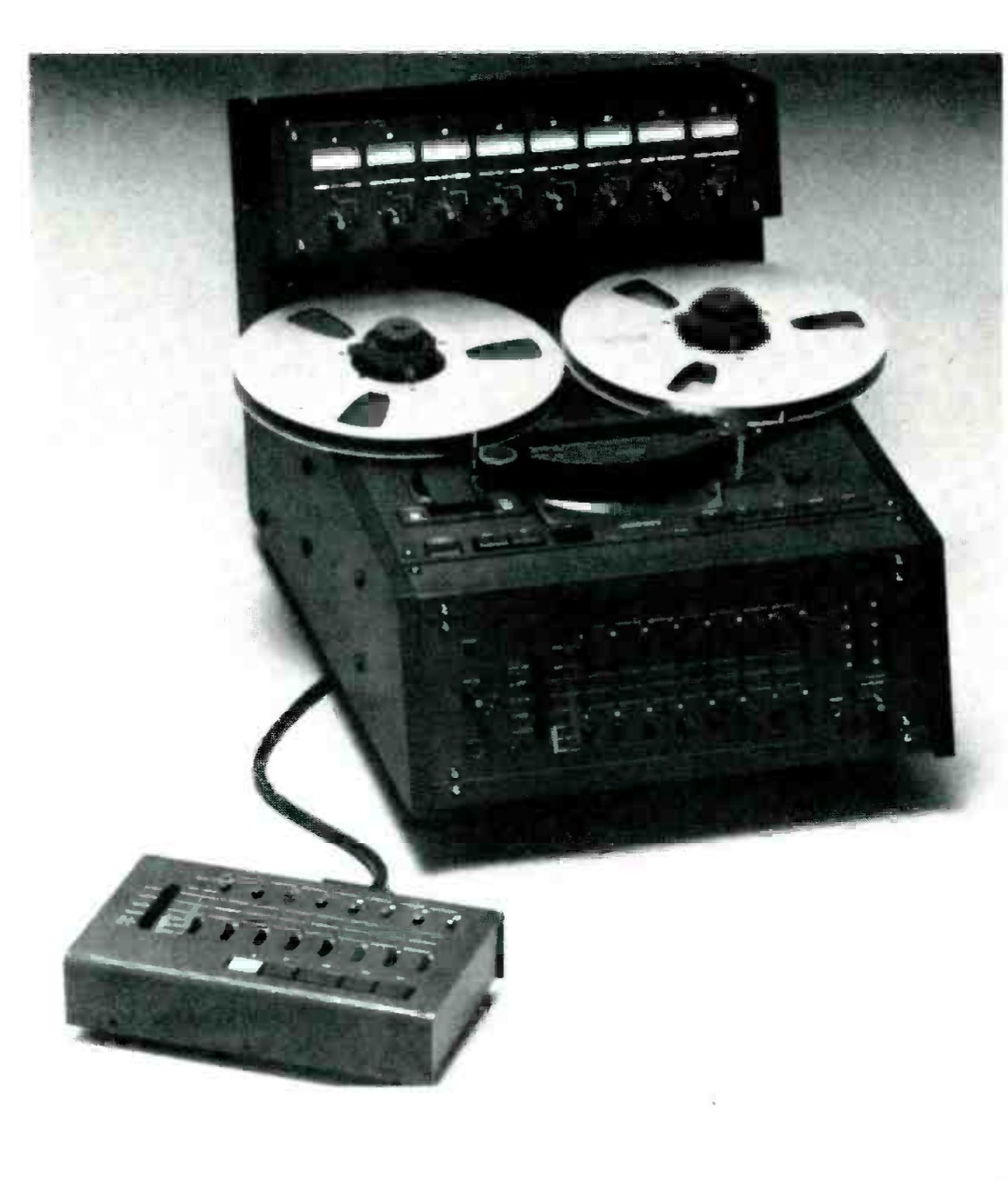 ⤢ zoomThe MARK III/8 photographed from a high three-quarter angle on a pale ground: a meter bridge of eight meters with a knob under each across the back, two metal reels on the flat transport, the transport buttons and the sloping front panel of channel switches below, and the remote control unit in the foreground on its cable.
I was excited at the prospect of doing a "hands-on" review of the latest Otari half-inch 8-track tape recorder. Over the years, in addition to working in traditional (one-inch, eight-track) recording environments, I have had considerable involvement with the half-inch eight-track format. In fact, I had been very involved with the original machines that boasted the then-new format, and served as a consultant in the design of the second-generation machines. I have also had quite a number of hours using Otari's now discontinued half-inch eight-track recorder, the "8D."
When MR&M editor John Woram asked me to do a "Hands-On Report" on the Otari MX-5050-MKIII-8, it fit perfectly into my plans. I had just convinced myself to get back into my role as a musician (I hadn't played the drums in about six years, except for digital drums—thanks to the wizardry of Roger Linn). I've just finished the construction of a new music room which is to serve at different times as a studio, a rehearsal hall, and a test lab for new and existing Sound Workshop console designs. The "studio" is presently outfitted with a 20 x 16 Sound Workshop Logex Mixing Console with assorted peripheral gear, the now-resident full Yamaha Recording Series Drum Kit, the Linn LM-1 Drum Computer, a Fender Bass and various keyboards including an exciting new design from Digital Keyboards called "Synergy." Most of my musician friends don't need much of an excuse to drop what they are doing to get involved in a recording project, so I figured I had the proper ingredients to give the Otari a good workout.
I received the Otari after it had undergone a series of lab tests by Len Feldman. Because of this, I planned to limit the scope of this report to my own in-use experience. Since I knew that Len would give a full description of the features of the machine, as well as a total overview of its electrical performance, I planned not to worry abut every small detail, but to use the machine as if I had just purchased it. Since I have a tendency to review everything I purchase anyway, this approach seemed perfect.
The machine comes in one large carton and the packaging design is excellent. It is definitely the kind of box that should be saved, in case the machine ever has to be shipped to another location. Speaking of shipping to other locations, the MX-5050 is not a small machine. Consistent with its totally professional design, it wants to be installed and enjoyed. If it is being used in a home environment, it will not be easily moved to the studio to transfer the tracks to a larger format machine—although it is not impossible.
Interfacing
After unpacking, I set up the machine and interfaced it to the Logex console. Checking out the rear panel, it was apparent that the interface would be simple and straightforward. The eight inputs and eight outputs terminate in XLR-type connectors. Both the inputs and outputs are unbalanced, but are fully compatible with both balanced and unbalanced circuits. The rear panel also contains an impressive array of alignment controls. Among these controls are output and input level switches marked H and L(High and Low). I ensured that all switches were set to High for proper interface with the +4 dBv levels of the console. (The L position of the input and output switches sets the levels for -8 dBv).
All of the setup and my first dealings with the machine were accomplished without looking at the instruction manual. While it is true that I have much experience with tape machines, and I have used other Otari products, I feel that my ability to proceed unaided was mostly due to the logical and straightforward layout and function of this machine. Both novice and professional engineers will find this a refreshing machine to use. I used the instruction manual as a technical reference, and in this fashion it served me well. It is not a step-by-step operation guide; it is factual in nature and provides a wealth of data and drawings, but it will not hold you by the hand and teach you the art of multi-track recording. This once again fits into Otari's professional approach.
Once the machine was hooked up, I wandered around the front panel. Like the rear, it's logical, complete and straightforward. To check out my installation, I turned the TEST OSC (Oscillator) switch to 1K, and pressed the ALL INPUT button. The input LEDs assured me that all the channels were in the Input mode. A glance at the meters indicated all channels at "0," while a look at the console indicated the same. The rest of the installation check went as smoothly.
After a more detailed examination of the front panel, I began to feel right at home with the Otari machine. There are master buttons for switching all eight channels into Input, Sync, or Reproduce, and there are also provisions for allowing each channel to be switched individually into these three modes.
Regardless of how the channels are controlled, each channel has three LEDs to indicate which mode it is in. Additionally, there is a master button that diverts channel control to the optional remote control unit (model CB-110). Even when under this EXTERNAL CONTROL, the LEDs on the machine indicate channel status.
For each of the eight channels there is also a ready/safe switch with an associated LED. When a channel is put into record ready, the LED flashes to indicate the ready status. When actually recording, that channel's LED goes into a full-on state. This in combination with the other LED status indicators provides a vital and very graphic indication of exactly what the machine is up to at all times.
Of course, as with any professional tape recorder, the proof of performance comes when the record light comes on and the musicians start to play. In essence, a tape recorder has two main functions to perform: It must make a great sounding high quality recording, and it must be easy to use. In the case of a professional multi-track tape machine, easy to use translates into fast, flexible and friendly. This operator ease is equally important in a professional studio, a home studio, or a production facility.
The MX-5050 in Use
To most fully evaluate the operation of the Otari, I used it on several different sessions, where I served as recording engineer, musician, or both. The machine felt very comfortable and operating it came second nature with few exceptions. The transport was responsive to all commands and the machine has microprocessor control of its motion sensing and full dynamic braking systems. Tape handling seemed smooth and safe. The microprocessor also controls the digital tape timer. This LED readout indicates hours, minutes, and seconds in both positive and negative increments. A problem with the readout stems from its physical position. The transport on the Otari is in a horizontal plane and the function control panel is vertical at the front of the machine. In setting up the machine I positioned it so that the front function panel was at eye level, with the transport controls easily within reach on the top. However, this kept me from seeing the time readout which is mounted flush with the transport; it was a bit inconvenient. The truth is that even some of the most expensive recorders in the world suffer from this same syndrome. I have heard that there are prisms available (probably from Edmund Scientific) that would allow viewing the timer from the front...Sounds like an inexpensive solution.
Tied in with the timer is a search-to-zero function. It seems like this is a cross between the consumer-oriented memory rewind function and the professional search-to-zero. It functions like a search in that, regardless of the tape position, when MEMORY is pressed the transport goes into whatever mode it must to return to zero. The problem is that when it reaches zero, it simply issues a stop command. If speed had been attained by this time, the transport could overshoot zero by as much as 35 seconds at 15 IPs. About one-half second after the tape stops, MEMORY can be pressed again, and now the tape will stop within a few seconds of zero. Two other inconveniences exist with the search-to-zero function: 1) It cannot be engaged from the record mode. This means that after a take one must press STOPand then MEMORYto return to the beginning of the song. 2) You cannot make the machine search to zero and then play without waiting for the machine to stop first. It would be nice while recording to be able to stop the recording just by pressing MEMORY, and then lean back while the machine shuttles back and plays that magic take.
On the other side of the ledger, all of the channel function controls are perfect. During recording, overdubbing, or punch-ins, the "ready/record" channels automatically switch from sync to input (and vice versa) just as they should. There is absolutely never a time when more than one finger is needed. Critical communication with the musicians is maintained during all normal machine functions. (Record/ready channels did drop out of input momentarily when stop was engaged. This is a minor inconvenience, and the factory tells me that it is being looked into.) The layout of the function panel, and its switches and LEDs, proved to be exceptional in use.
The sonic performance of the Otari was excellent. I didn't do any electrical measurements until after I had done sonic evaluations. My electrical measurements confirmed what my ears had heard. Response was extended and smooth. This is especially important when doing sound-on-sound recordings (bouncing tracks). In addition, signal-to-noise and cross talk were better than expected, given the half-inch 8-track format. Is it as good as a one-inch 8-track machine? No.
Where it falls short is in its ability to handle high-frequency dynamic transients. But, of course, that is where all analog tape recorders fall off. While I didn't do an A/B with a one-inch 8-track machine, it is apparent that a one-inch would offer more overall dynamic range and transparency than a half-inch machine. But this comes as no surprise. Certainly the Otari half-inch machine used with an overall consciousness of the limitations of its format could outperform a one-inch machine used with a disregard of conservative recording techniques.
Summary
My overall impression of the Otari MX-5050-MKIII-8 is that it is a fully professional and competent tape machine in performance and function. It performs efficiently and effectively and is easy to adapt to.
My only criticism is with the timer and related search-to-zero functions. Since my initial impressions, two things have occurred. I have been sent the optional CB-110 transport/function remote control, and I have spoken to the factory about my disappointment with the search-to-zero functions.
The remote is just what I needed. On one small panel are the channel function controls, the transport controls, and the timer readout. This allows the machine to be located remotely, and all relevant functions to be performed from the remote panel. This unit adds to the convenience of the machine, and alleviates my criticism of the location of the timer.
After speaking with the factory about the search-to-zero functions, I was informed that soon after this is in print the optional auto-locator will be available. I was given a run downdown of the features of this unit and it will not only accurately search and stop precisely at zero, but it also has eight memories for various search cue-point functions, and a host of other functions that I haven't even seen on 24-track auto-locators. These include head and tail guard memories, and complete offset of existing cue-point when zero is reset. I hope to review this unit completely when it becomes available.
Since I knew that Len Feldman was writing a lab report of the Otari machine, I have assumed that he has at least described all of the other features included in this machine. These include convenient editing provisions, a simple but handy headphone mixer and amplifier, VU and peak metering, variable speed operation, internal test oscillator, tape lifter defeat, calibrated and variable line input level controls, and extensive alignment capability.
Just to familiarize myself with the machine and to confirm my sonic judgements, I did briefly go through an alignment of one channel. As long as you allow access to the back of the machine, the alignment facilities are excellent. I especially appreciated the EXT OSC jack which allowed me to feed all eight tracks without having to involve the console. This is especially convenient in the studio where the console can be used for other functions while the machine is being aligned. The phone's mixer/amp also comes in handy here. Of course these features and the built-in oscillator make the fast system check very simple.
Based on my in-use evaluation of the Otari MKIII-8, I can recommend it highly as a professional 8-track recorder applicable in both music recording and production environments. Its performance both sonically and operationally is excellent. While I can only speculate on its long-term reliability, based on its construction and competent alignment provisions, as well as my experience with other MX-5050 machines, it appears that it will maintain its high performance standards over the years. For those considering moving up to an 8-track machine, the Otari can be considered a big step in the right direction. In many applications, its initial cost, plus the savings on tape, may make it an attractive choice where only 1-inch machines may have been considered in the past.