Period press · Recording Engineer/Producer, April 1982 · scan pages 9–10
An Otari Varispeed Modification
View source PDF ↗And you might consider this:
An Otari Varispeed Modification
In the December issue of R-e/p I showed a modification to the Otari MX-5050B that improved the distortion specs by eliminating the output transformers ("The Pre-Distortion Phenomenon," December 1981, page 96). Shortly after that article was completed, I discovered another useful improvement that will be of interest to Otari owners. This modification allows the varispeed range to be greatly increased beyond the normal ± 7%. Actually, I would like to show two different ways to do this: the first one I figured out and, although it is not quite as simple as changing a few resistors, it will allow a continuous sweep of the tape speed from around 1 to nearly 30 IPS. When I called Otari Corporation (just to be sure there wasn't anything important being overlooked), I spoke with Tom DeFiglio, an applications engineer, who described an even easier method, although the range will only be increased to 20%.
Figure 1 shows the partial schematic for the capstan motor amplifier circuit; while R7 and R8 (etc) are shown as only one resistor, there are actually two components on the circuit board. Normally, the fixed speeds are selected by applying a voltage to the appropriate points marked H, M, and L, with the varispeed pot connected between R14
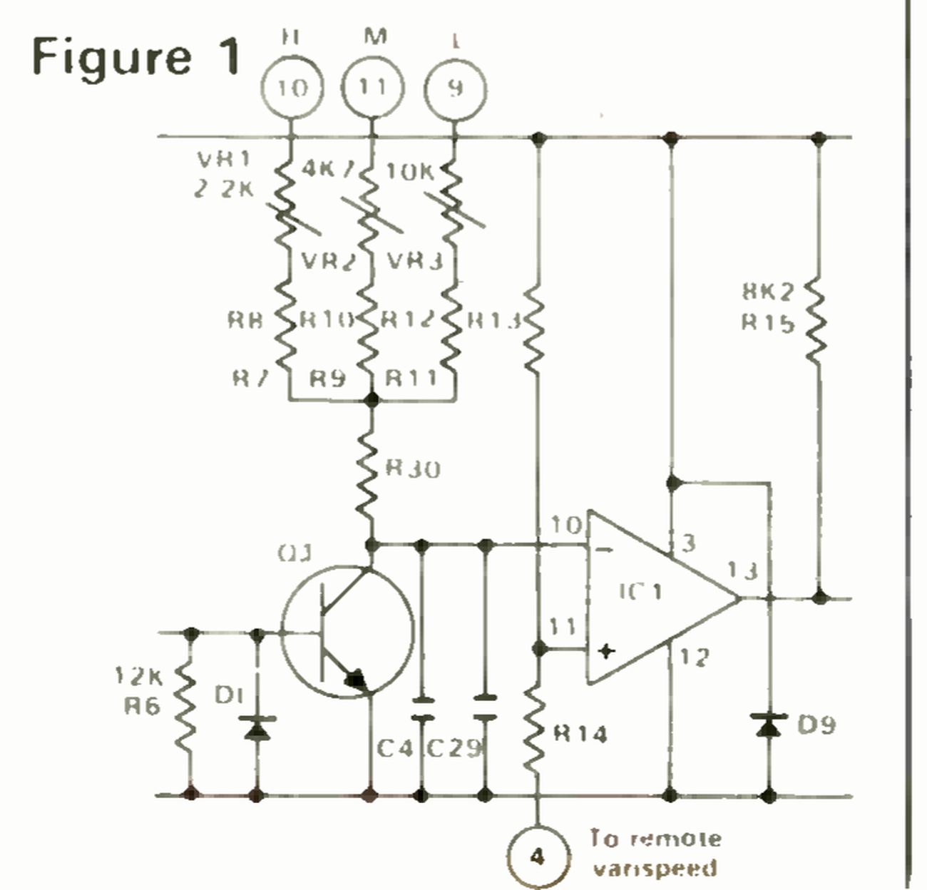 ⤢ zoomFigure 1, a partial schematic of the capstan motor amplifier: speed-select inputs H, M and L (pins 10, 11 and 9) run through trimmers VR1 2.2K, VR2 4K7 and VR3 10K and then resistor pairs R7/R8, R9/R10 and R11/R12, joined through R30 to transistor Q1 and the inverting input (pin 10) of op-amp IC1; R13 and R14 set the non-inverting input (pin 11), and R14's lower end goes to pin 4, marked To remote varispeed.
Figure 1
— continued . . .
An Otari Varispeed Modification
and ground. When not in the varispeed mode, a fixed 200-ohm resistor is connected in its place. It is interesting to note that although only two fixed speeds are provided on the front panel, a third speed is available via an internal switch on the rear of the control card.
For the Otari-designed modification, six fixed resistors are changed, and the original potentiometer is still used to vary the speed. Tom DeFiglio of Otari wisely pointed out that before you touch anything, you should record a 10 kHz tone on tape at each speed, which will be used as a reference later on to recalibrate fixed-speed potentiometers UR1, UR2, and VR3. Other than that, simply perform the resistor changes as listed, and you will have increased the control range to 20%:
| (Original) | (New) | ||
|---|---|---|---|
| R7 | 18 kohm | to | 20 kohm |
| R9 | 39 kohm | to | 33 kohm |
| R10 | 2 kohm | to | 12 kohm |
| R12 | 0 kohm | to | 12 kohm |
| R13 | 1K8 | to | 680 |
| R14 | 1K8 | to | 470 |
For the method I devised (shown in Figure 2), you will not have to change any of these fixed resistors; therefore, the trimpots will not need to be recalibrated. You will have to
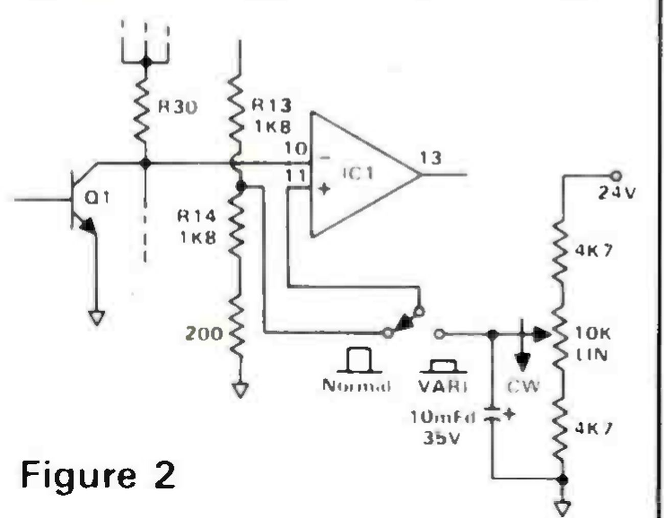 ⤢ zoomFigure 2, the author's varispeed circuit: Q1 and R30 feed pin 10 of IC1 as before, and pin 11 is now routed out to a Normal/VARI changeover switch; in Normal it returns to the junction of R13 1K8 and R14 1K8, with the fixed 200-ohm resistor below R14 to ground, and in VARI it takes the wiper of a 10K linear pot, marked CW, set between two 4K7 resistors from 24V to ground, with a 10mFd 35V capacitor from the wiper to ground.
Figure 2
do a bit of rewiring, however, and the original 500-ohm potentiometer must be replaced with a 10K linear type. I was not able to find a new pot with the same kind of switch attached, so instead I rewired the memory rewind switch to turn the varispeed on and off. (I hardly ever used that function anyway.) Also, you will need to make a cut on the PC board foil to route pin 11 of IC1 out to the switch. Be sure to use the same 200-ohm resistor that was wired to the old varispeed pot, since that was in place when the original speed alignment was performed.