Period press · Studio Sound, June 1983 · scan pages 38–39, 74, 76, 78 and 80–81Review
Otari MX5050-Mk III/8
View source PDF ↗Otari MX5050-Mk III/8
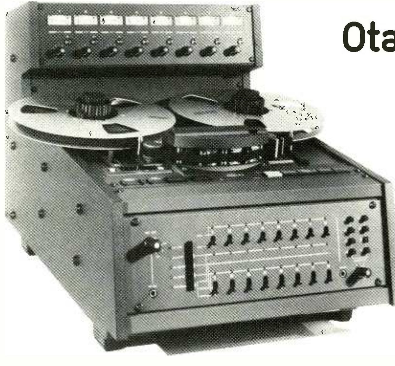 ⤢ zoomThe Mark III/8 photographed from a high three-quarter angle in black and white: the eight VU meters and their level controls in the meter bridge on top, two large reels on the transport, the head block under its cover, and the sloping front panel with two rows of eight track switches, the two columns of headphone-selector buttons at right and the headphone jack; the first letters of the review's headline intrude at top right.
MANUFACTURER'S SPECIFICATION
Tape width and tracks: ½ in (12.7 mm) tape; eight tracks (0.04 in or 1.0 mm track width).
Tape speeds: 7½ and 15 in/s (190.5 and 381 mm/s); maximum deviation ±0.2% measured with 1.5 mil (0.038 mm) tape.
Reel sizes: ½ × 10½ in NAB.
Heads: three—8-track in-line, erase (ferrite), record, reproduce (both hard permalloy).
Motors: capstan—DC servo-controlled motor (pitch control range ±7%); reels—two torque motors.
Rewind time: approximately 100 s for 2,500 ft (760 m) NAB reel.
Operating position: horizontal (table top type).
Power requirements: 100, 117, 220, 240 V, 50 Hz or 60 Hz, single phase AC.
Power consumption: 150 W.
Operating environment: 40° to 104° F (5° to 40° C) 20% to 80% relative humidity.
Storage environment: −5° to 113° F (−20° to 45° C).
Dimensions: (whd) 17.3 × 17.3 × 26.6 in/438 × 438 × 675 mm.
Weight: 77 lb/35 kg.
Mounting: coloured leatherette-finished cabinet.
Remote control unit: CB-110 remote control unit (remote control functions of transport and amplifier and timer) CB-114 remote control unit (remote control function of transport).
Connectors: line input, line output—standard 3-pin XLR; external oscillator—standard single-conductor phone jack; phones—standard 2-conductor phone jack.
Inputs: line—variable or fixed level front panel switch selectable, unbalanced 50 kΩ; fixed level—+4 dBm or −8 dBm switchable (minimum −9 dBm or −18 dBm); external oscillator minimum 18 dBm, unbalanced 10 kΩ.
Outputs: line fixed level +4 dBm or 8 dBm rear panel switch selectable; load impedance more than 600Ω; maximum line output level +21 dBm with 600Ω load.
Headphone Jack: −19 dBm with an 8 Ω load; load impedance—8 Ω or greater.
Equalisation: NAB or IEC for 7½ and 15 in/s.
Frequency response: record/play—15 in/s, 40 Hz to 25 kHz ±2 dB; 7½ in/s, 20 Hz to 20 kHz ±2 dB. Sync/replay—15 in/s, 40 Hz to 15 kHz ±3 dB; 7½ in/s, 30 Hz to 10 kHz ±3 dB. Specifications refer to a 1 kHz reference when recorded on 3M type 226.
Signal-to-noise ratio: 15 and 7½ in/s NAB- or IEC-weighted 70 dB. unweighted 66 dB.
Crosstalk: better than −55 dB.
Wow and flutter: NAB-weighted, 15 in/s less than 0.05%; 7½ in/s less than 0.06%.
Distortion: less than 0.5% at 1 kHz at 250 nWb/m.
Erase efficiency: greater than 70 dB.
Test oscillator frequency: nominal 1 kHz and 10 kHz.
Bias and erase frequency: 200 kHz.
Peak indicator: trigger level—1040 nWb/m (15 dB above Ampex operating level) recorded flux level.
NOTE: signal-to-noise ratio is measured with respect to a recorded level of 1040 nWb/m to biased tape noise when using 3M type 226 magnetic tape. Unweighted—using a 30 Hz to 18 kHz RC filter to eliminate noise outside the audio spectrum. Weighted—using an NAB or ASA A-weighted filter and a 1 kHz reference.
Manufacturer: Otari Electric Co Ltd, 4-29-18 Minami, Ogikubo, Suginami-Ku, Tokyo, Japan.
UK: Otari Electric (UK) Ltd, 22 Church Street, Slough, Berkshire.
USA: Otari Corporation, 2 Davis Drive, Belmont, CA 94002.
THE Otari MX-5050 Mark III/8 is a portable ½ in, 8-track machine capable of using 10½ in NAB spools or cine centred spools with excellent NAB adaptors being provided. Whilst the machine is intended for table top use and is fitted with four good non-slip feet, a pedestal with four castors is available as an optional extra as is the remote control unit.
A ¼ in alloy plate forms the basis of the tape transport with alloy 'spider' castings being secured to the sides of the alloy plate. The sheet steel base of the machine is attached to the alloy sides with the remainder of the housing being formed from sheet steel, the sides having a substantial wooden trim.
To the back of the machine the eight illuminated VU meters face the operator in a penthouse which includes switched input level potentiometers with the switches giving a fixed calibrated input sensitivity.
Individual track switching is in two rows of eight switches with four associated rows of LEDs on an almost vertical panel at the front of the machine. The top row are 2-position toggle switches giving the ready/safe function for the eight tracks. When in the ready position a red LED flashes by the switch, the LED being permanently illuminated once the track is put into record.
In the second row the toggle switches have three positions for selecting the output between the input, normal replay or sync replay. Three LEDs in vertical array above the switches indicate the current status of each track—yellow for input, green for sync and orange for replay. To the left of this arrangement a vertical row of five interiocked pushbuttons provide overall control with LEDs indicating the status which may be all tracks replay/sync/input, individual control or remote control.
At the right of the front panel a ¼ in headphone jack provides monophonic monitoring of any combination of tracks with the selection being by means of eight locking pushbutton switches. To the left of the panel a further ¼ in jack is fitted for a test input to all tracks. A 4-position rotary switch feeds all tracks from the eight inputs, the single test input or an internal test oscillator at 1 kHz or 10 kHz.
To the front of the tape transport a small panel extending the width of the machine has the normal tape motion controls to the right, the switches being momentary pushbutton switches with the record button not being interlocked. A red LED near the record button flashes when any tracks are in the ready status and is permanently illuminated in the record mode with or without any tracks recording. This means that any track may be dropped into record or out of record with the safe/ready switches or any preselection of tracks may be manipulated with the record button with or without the tape in motion.
To the left of this panel locking pushbutton switches provide the power on/off, reel size (tension) selection and selection of two tape speeds which are normally 15 and 7½ in/s. Within the section there is a momentary button for dump editing, and a green warning LED showing when dump edit is selected.
Within the tape transport, real tape time is indicated in hours, minutes and seconds with the timer going negative when reversing past zero. One pushbutton within the timer resets the indication to zero with another button moving the tape at high speeds to zero indication. At the centre of the transport a variable speed potentiometer is provided; pulling out the knob initiates variable speed operation with a red LED giving warning of this condition.
The final operator control is a mechanical cue lever which removes the tape lifters in the headblock from the tape path in the fast and stop modes.
The tape transport is conventional in design with the two AC spooling motors being fitted to the transport plate on folded steel brackets. The spools are directly driven and have height adjustment available, with the far end of the motor shafts having solenoid-operated band brakes.
From the pay-off spool the tape passes over a rather flimsy spring-loaded tension arm before the tape timer roller which is equipped with a tachometer disc. Following this is the removable headblock secured on to the transport plate by screws in three fixed guide posts, the head wiring being fitted with connectors. The three heads are suspended from an alloy plate which is secured on to the guide posts with positive azimuth adjustment for the record and replay heads.
The first fixed guide is located before the erase head, the second between the erase and record heads with the third at the exit from the head block. No further guides or flutter rollers are within the head area which is surmounted by a hinged cover fitted with a splicing block. From the head area the tape feeds to the direct drive metal capstan, with the long shaft DC motor being screwed to pillars fitted to the transport plate.
The large diameter pinch roller is solenoid operated via a reasonably substantial linkage which also operates the tape lifters in the headblock. Finally before the take-up spool, a further rather flimsy spring-loaded tension arm operates a 'tape present' microswitch.
Within the case the large laminated power transformer is slung below the transport plate—a practice which I do not care for in view of the weight of the transformer and heating of the transport plate. A printed circuit board in the base contains the power supplies and the microprocessor-driven control logic with various other subsidiary boards being used for other control and display functions.
All the audio electronics are contained on eight plug-in boards under the VU meter panel, these boards and one other being positively located in sockets on a mother board.
The arrangement is such that all normal preset controls in the form of conventional potentiometers can be screwdriver-operated through holes in the rear panel, each audio board having 14 potentiometers and two slide switches. The two switches give a choice of input and output levels such that the recorder may be interfaced with other professional or domestic equipment.
Separate potentiometers are provided for setting 0 VU and the threshold of the peak indicator LEDs located within the VU meters. Record and replay equalisation at high frequencies have separate adjustments for the two tape speeds with each track having a bias control (no master bias control being fitted) and an oscillator input level control.
In addition to HF equalisation the replay channels have a low frequency control with the sync replay using the replay equalisers. The remaining audio controls are all level controls with the secondary board in the audio department having a control for setting the 10 kHz oscillator level and a standby on/off switch. The latter allows all channels in the standby mode to automatically switch to input in the stop and fast wind modes.
Whilst obviously built to a price the standard of construction was generally good from a mechanical point of view with the printed circuit boards being to a first class standard with excellent component identifications. Furthermore the instruction and maintenance manual was very good including circuits, parts lists, exploded diagrams and maintenance information.
Whilst access to the tape transport components was reasonable, the internal wiring was rather untidy and not all components were fitted with connectors such that replacing some transport components and printed circuit boards involves soldering.
All connections are located at the bottom rear of the recorder with the audio connections being unbalanced at XLR connectors. Power input is via an IEC connector with the internal fuses being properly identified.
Two multipole connectors allow the use of the remote control unit and also an autolocator which will be available shortly. There is also the possibility of linking the machine with a synchroniser.
Remote control unit
Connecting to the recorder with approximately 40 ft of multiway cable the remote control unit duplicates all tape movement and track selection functions plus the tape timer. It is contained in a case about 12 in (w) by 7 in (d) fitted with a tilting foot with the locking connector for the cable being under the remote unit.
On top, the two horizontal rows of track selection switches with their associated LEDs have the same format as on the recorder, again with interlocked pushbutton to the left for overall control of all input/replay/sync and individual settings.
The tape time again has a reset and return to zero button with the tape movement controls being identical to those on the recorder.
Entering the remote mode inhibits all track selection controls on the recorder but all the indicators on the remote unit and the recorder remain active.
However the tape timer buttons and the tape movement controls (including record) were always working at the remote unit and the recorder, a feature which I do not like.
Inputs and outputs
The unbalanced audio inputs were found to have an impedance of 47 kΩ in the high level setting or 50.5 kΩ in the low level setting, both remaining constant with the input gain. As supplied 0 VU corresponded to +4 dBm or −8.5 dBm in the calibrated condition for the high and low sensitivity switch settings with the maximum uncalibrated sensitivities being −8.5 dBm and −18.5 dBm.
With a capability of handling in excess of +30 dBm together with the high input impedance and wide sensitivity range, the inputs are fully compatible with domestic and professional environments.
At the audio line outputs there was again a wide range of level from an unbalanced source with an impedance less than 1Ω. As supplied the output for a fluxivity of 320 nWb/m was +5 dBm or −7 dBm depending upon the output level switch setting, these levels corresponding to +1 VU. The maximum output capability was +21.5 dB.7 V or +20.8 dBm loaded into 600Ω with 0 VU corresponding to +4 dBm or —8 dBm depending upon the setting of the output level switch. Relative to these settings the output level preset offered a range up to +10 dB boost with the record level preset having an adequate range of +4/−5 dB.
The monophonic headphone output had a maximum drive capability of 10 V RMS from a source impedance of 148 Ω suitable for virtually any type of headphones.
At the external oscillator input the impedance was adequately high at 21.3 kΩ with 380 mV being required for an indication of 0 VU in the calibrated gain settings independent of the gain switch position but with the variable gain control active in the uncalibrated position.
Frequency response
When using the external oscillator input for alignment the frequency response to the VU meters or the line outputs was not particularly satisfactory with −1 dB points at 80 Hz and 18 kHz falling to −3 dB at 40 Hz and 33 kHz.
The frequency response from the input to the output in the direct mode was reasonably satisfactory as shown in Fig 1 with −1 dB point at 12 Hz and at 18 kHz. Checking the replay frequency response with a calibration tape showed that the machine had been accurately calibrated at both tape speeds with the response at 15 in/s being +0.6 dB, −1.0 dB up to 18 kHz reference 1 kHz.
The optimised record/replay frequency response at 15 in/s is shown in Fig 2 and that at 7½ in/s in Fig 3 both showing reasonable low frequency head contour effects and a very flat response. The −1 dB high frequency point at the two speeds were at 26 kHz and 18 kHz falling to −3 dB at 30 kHz and 21.7 kHz.
In the sync mode as is normal the high frequency performance was degraded compared with the replay mode; however, the performance at both 15 in/s and 7½ in/s was satisfactory as shown in Fig 4 and Fig 5.
Fig 6 shows the very sensible range of the high and low frequency equalisers for the NAB equalised machine at 15 in/s with an identical range at 7½ in/s. Similarly the record equalisation is well contrived with a sensible range as shown in Fig 7 for BASF SPR-50 tape at 15 in/s when over biased 3 dB at 10 kHz.
In addition it was found that the available range of bias was more than adequate with the bias oscillator being buffered so that the number of tracks in record had no measurable effect upon bias. Leakage of the erase head on to adjacent tracks as determined by recording 20 kHz at 15 in/s on one track and then recording both adjacent tracks with bias and measuring the loss of the 20 kHz level, was negligible.
Noise
Noise as measured at the line outputs was virtually identical for the eight channels. As expected, noise varied 12 dB depending upon the setting of the output level switch, this being equal to the change in output level. Whilst the input level switch had no effect upon noise, setting the unit to the variable input sensitivity mode increased noise irrespective of the gain setting with the increase varying 0.5 dB with the setting of the gain control such that it decreased with increasing gain.
Noise in the replay mode without tape and with BASF type SPR-50LH tape recorded with bias alone was as shown in Table 1 in the replay mode referred to a fluxivity of 320 nWb/m.
Table 1 shows a very good margin between machine noise and tape noise, there being a complete absence of hum and other unwanted tones in the output. As might be anticipated noise in the sync mode was good and still offered an excellent standard of performance with reduced bandwidth as shown in Table 2.
When switched to the input the noise at the output was fairly close to the replay amplifier noise (see Table 3), particularly when weighted, but the margin between tape noise and amplifier noise made the amplifier noise of little significance.
In spite of the lack of any form of head screens the unit seemed to be remarkably free of hum pickup from external sources.
TABLE 1 — Reference level (320 nWb/m) to noise
| Measurement method | No tape, 15 or 7½ in/s | With tape, 15 in/s | With tape, 7½ in/s |
|---|---|---|---|
| 22 Hz to 22 kHz RMS | −65.0 dB | −55.8 dB | −58.0 dB |
| A-weighted RMS | −72.0 dB | −59.5 dB | −62.0 dB |
| CCIR-weighted RMS | −66.2 dB | −51.5 dB | −53.0 dB |
| CCIR-weighted quasi-peak | −62.0 dB | −48.0 dB | −49.5 dB |
| CCIR-weighted ARM | −72.5 dB | −58.0 dB | −60.0 dB |
TABLE 2 — Reference level (320 nWb/m) to noise
| Measurement method | No tape, 15 or 7½ in/s | With tape, 15 in/s | With tape, 7½ in/s |
|---|---|---|---|
| 22 Hz to 22 kHz RMS | −62.5 dB | −56.5 dB | −58.0 dB |
| A-weighted RMS | −70.4 dB | −61.0 dB | −62.5 dB |
| CCIR-weighted RMS | −64.5 dB | −52.5 dB | −54.0 dB |
| CCIR-weighted quasi-peak | −60.5 dB | −48.5 dB | −50.0 dB |
| CCIR-weighted ARM | −71.5 dB | −59.0 dB | −60.5 dB |
TABLE 3 — Reference level (320 nWb/m) to noise
| Measurement method | Fixed input | Variable input |
|---|---|---|
| 22 Hz to 22 kHz RMS | −73.0 dB | −70.0 dB |
| A-weighted RMS | −75.2 dB | −72.0 dB |
| CCIR-weighted RMS | −66.2 dB | −63.0 dB |
| CCIR-weighted quasi-peak | −62.0 dB | −59.0 dB |
| CCIR-weighted ARM | −72.5 dB | −69.5 dB |
Distortion
Using BASF type SPR-50LH tape over biased 3 dB at 10 kHz when running at 15 in/s the third harmonic distortion was measured when recording a fluxivity of 320 nWb/m. Good results were obtained being 0.20% at 15 in/s or 0.28% at 7½ in/s.
At both tape speeds the maximum output level for 3% third harmonic distortion was satisfactory at +9.5 dB reference 320 nWb/m with other harmonics being at a very low level.
Both the record and replay amplifiers could handle in excess of +15 dB reference 320 nWb/m before serious distortion. Recording and replaying a 1 kHz squarewave produced Fig 8 at 15 in/s with a relatively similar amount of overshoot at 7½ in/s.
Wow and flutter etc
IEC-weighted peak wow and flutter was measured at both tape speeds at the beginning, middle and end of a reel of BASF type SPR-50LH tape and found to vary quite widely but to remain at a good standard (see Table 4).
TABLE 4
| Tape speed | Beginning | Middle | End |
|---|---|---|---|
| 15 in/s | 0.042% | 0.065% | 0.10% |
| 7½ in/s | 0.075% | 0.055% | 0.08% |
A spectrum analysis of a 10 kHz tone recorded and replayed at 15 in/s shown in Fig 9 demonstrates the flutter components around the carrier. The main flutter components which are located at approximately ±15 Hz and multiples thereof from the carrier result from the 7.801 mm diameter capstan. In other respects the spectrum is very clean.
Drift from one end of a 2,400 ft reel to the other was reasonable at 0.032% with the relationship between the two tape speeds being better than 0.016%. The variable speed function which is available in both replay and record had a range of +7.1% to −8.3% with reasonably accurate control by its 270° potentiometer. The phase drift between the outer tracks at 10 kHz and 15 in/s as shown in Fig 10 peaks about ±12°.
Other matters
Crosstalk between adjacent tracks in the replay mode was to a good standard as shown in Fig 11 but crosstalk in the sync mode requires some caution in use. This is always a compromise between the sync frequency response and crosstalk. When recording one track and replaying the adjacent track in the sync mode the result is shown in Fig 12 which demonstrates an effective gain above 9 kHz. However, in practical use it is most unwise to use adjacent tracks and the crosstalk improves by 23 dB overall with one track left between the operational tracks.
The VU meters were found to be correctly set for Ampex 456 tape and to have the correct rectifier characteristics and ballistics. However the peak indicators were set at too high a level, but this is a simple matter of resetting the preset controls. The response time of the peak indicators for a reasonably visible indication was about 5 ms.
Erasure of a 1 kHz tone at 7½ in/s varied from track to track but was always acceptable at greater than 82 dB using BASF type SPR-50 tape.
The internal alignment oscillator was a useful feature with low distortion (worst case 0.3% second harmonic at 1 kHz) and accurate frequencies of 987 Hz and 9,932 Hz.
In operation the machine handled tape well at sensible tensions around 120 g when running but with a rather heavy boost when starting. Failure of the mains supply brought the tape to a steady halt from any mode and the machine when set for 240 V operation worked quite happily at 200 V.
Summary
I have few criticisms of this machine which together with its remote control unit are well conceived.
The selection and range of the pre-set control was very good which made alignment straightforward with a good instruction and maintenance manual.
As the machine is built to a price the mechanical construction is not particularly solid, but more substantial machines cost very much more.
Hugh Ford
5050 SERIES MARK III/8
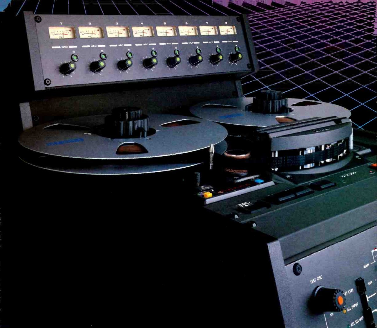 ⤢ zoomThe Mark III/8 photographed close up in dark tones against a purple and blue grid: the eight-channel meter bridge with its input level knobs, two metal reels on the transport, the head block under its cover and, at lower right, the corner of the front panel with the TEST OSC selector.
"...well conceived."
Hugh Ford, Studio Sound, May 1983
The Mark III/8, 1/2″ eight channel machine stands at the top of the range of 5050 Series recorders.
Built to exacting studio standards, the entire 5050 Series offer features and performance typically found only on recorders priced considerably more.
All models feature D.C. controlled capstans with ±7% variable speed; 10½″ reel capacity, plug-in head assemblies, built-in test oscillator, comprehensive and easily accessible calibration adjustments and selectable output level of either +4 dBm or −10 dBv. Certain models additionally offer active, balanced transformerless inputs and outputs. Every recorder features a microprocessor-controlled transport with an L.E.D. counter and return- to-zero as standard.
Optional accessories include a roll-around pedestal stand for all models, remote control facilities and a full-function autolocator.
Rugged, compact construction and specifications that meet critical professional standards are the hallmarks of all Otari recorders. Regardless of which format you require, a 5050 Series recorder will give you the confidence to meet the most demanding recording situations.
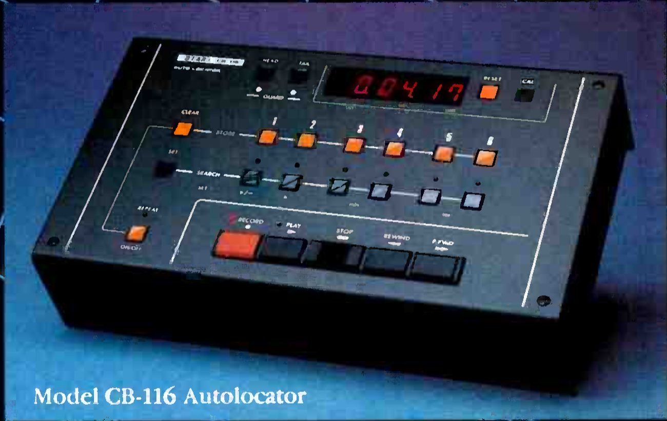 ⤢ zoomThe Model CB-116 autolocator photographed against blue: a sloping black console with a red LED time display reading 0 04 17, a row of orange store buttons and a row of search buttons for six locations, and the record, play, stop, rewind and fast-forward keys along the front.
Model CB-116 Autolocator
© 1983 Otari Electric(UK) Ltd.
To receive the complete text of Hugh Ford's exhaustive review of the Mark III/8, comprehensive brochures and price details, or to arrange your own "hands-on" review, call one of our authorised dealers now or contact us directly at 0753-38261 and ask for Mick Boggis.
The 5050 Series are built with quality you can hear and feel – affordability that makes Otari the "Technology You Can Touch."
Otari Electric(UK)Ltd.,Herschel Industrial Centre, 22 Church Street, Slough SL1 1TP, Berkshire, Tel: 0753-38261 Telex: 849453 OTARI G.
Authorised Dealers:
ITA
1-7 Harewood Avenue, Marylebone Road, London NW1 6LE
Tel: 01-724 2497/8 & 01-724 3768 Telex: 21879
TURNKEY
Brent View Road, London NW9 7EL
Tel: 01-202 4155 Telex: 25769
OTARI® Technology You Can Touch
Otari Corporation, Belmont, California (415) 592-8311 Telex: 910-376-4890. Otari Electric Co., Ltd., Tokyo, Japan (03) 333-9631 Telex: OTRDENKI J26604. Otari Singapore Pte., Ltd., 294-5370 Telex: R5 36935. Otari Electric Deutschland GmbH, Neuss, F.R. Germany 02101-274011 Telex: 41 8517691 OTEL D.