MX-5050BII Instruction Manual — Digital Edition · Part 4 · scan pages 43-48
Preventive Maintenance
This section provides information on preventive maintenance, cleaning demagnetizing, lubrication and electronic adjustment procedures which should be carried out periodically to maintain optimum performance. Also refer to Sections V and VI for more details on adjustments.
4.1 TEST AND MAINTENANCE EQUIPMENT REQUIREMENTS↑ TOP
Table 4-1 Test and Maintenance Items
| Item | Suggested Model | Used for |
|---|---|---|
| Head Cleaner | Otari ZA-51B | Cleaning the heads. |
| Isopropyl Alcohol | Any (Otari Cleaning Kit ZA-51B contains the above cleaning materials.) | Cleaning the tape guides, capstan, and capstan pinch roller. |
| Head Demagnetizer | Any | Demagnetizing the heads and tape guides. |
| Lubricating Oil | Otari Lubricating Oil PZ9E003 | Lubricating the capstan of the DC servo control motor. |
| Reproduction Alignment Tape | NAB 3-3/4 ips: MRL 21F101 7-1/2 ips: MRL 21T204 15 ips: MRL 21J205 IEC 7-1/2 ips: MRL 21T302 15 ips: MRL 21J303 | Setting the operating standard reference levels, and adjusting frequency response. (Refer to page 5-10.) |
| Audio Oscillator 20 to 20 kHz | Hewlett-Packard 204C or 209D | Setting record equalization |
| AC Voltmeter | Hewlett-Packard 400L or 400FL | Setting record and playback frequency response |
4.2 PREVENTIVE MAINTENANCE↑ TOP
For optimum performance, cleaning and demagnetizing should be performed after every eight hours of operation, and lubrication should be carried out at the recommended times as indicated below.
4.2.1 CLEANING↑ TOP
Oxide particles from the magnetic tape tend to collect on components in the tape path and degrade the performance of the recorder. The heads and all other components in the tape path must be cleaned after every eight hours of operation, or more frequently if visual inspection indicates cleaning is required. To clean the head assembly, proceed as follows:
(1) Lift the head cover as illustrated in Fig. 4-1.
(2) Clean each head stack thoroughly with a cotton-tipped applicator dampened with head cleaner.
CAUTION: WHEN CLEANING THE HEADS, USE ONLY THE RECOMMENDED SOLVENT (HEAD CLEANER) TO AVOID DAMAGING THE HEADS. KEEP THE HEAD CLEANER AWAY FROM PLASTIC FINISHES AND THE CAPSTAN PINCH ROLLER. DO NOT USE METAL TOOLS THAT CAN SCRATCH THE HEADS.
(3) Use isopropyl alcohol to clean all tape guiding components including the capstan shaft and the rubber capstan pinch roller.
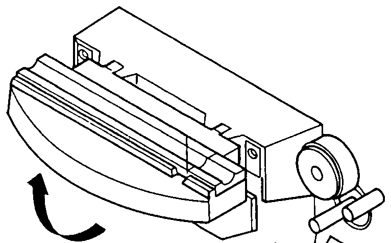 ⤢ zoomLine drawing of the head cover being lifted open, shown with a curved motion arrow indicating the hinge direction.
Fig. 4-1 Lifting the Head Cover
4.2.2 DEMAGNETIZING↑ TOP
The heads and tape guiding components in the tape path should be demagnetized after every eight hours of operation. These components can acquire permanent magnetization that increases signal noise and distortion, and partially erase high frequencies on recorded tape. Use a hand-held demagnetizer to demagnetize all components in the tape path as follows:
(1) Turn the unit's power off and remove any recorded tape near the transport. The tape could be partially erased by the demagnetizer.
(2) Lift the head cover as illustrated in Fig. 4-1.
(3) Cover the demagnetizer tips with adhesive tape to prevent scratching the head stacks.
(4) With the demagnetizer held away from the transport, connect the demagnetizer to a power source.
(5) Move the demagnetizer tips slowly close to the head, lightly touch the face of one head stack and slowly move the tips up and down the stack several times. Then slowly withdraw the demagnetizer as shown in Fig. 4-2.
(6) Repeat step (5) for each head stack.
(7) Repeat the procedure in step (5) for each guide and other metallic parts in the tape path.
(8) Move the demagnetizer slowly away from the transport at least three feet, and then disconnect the power from the demagnetizer.
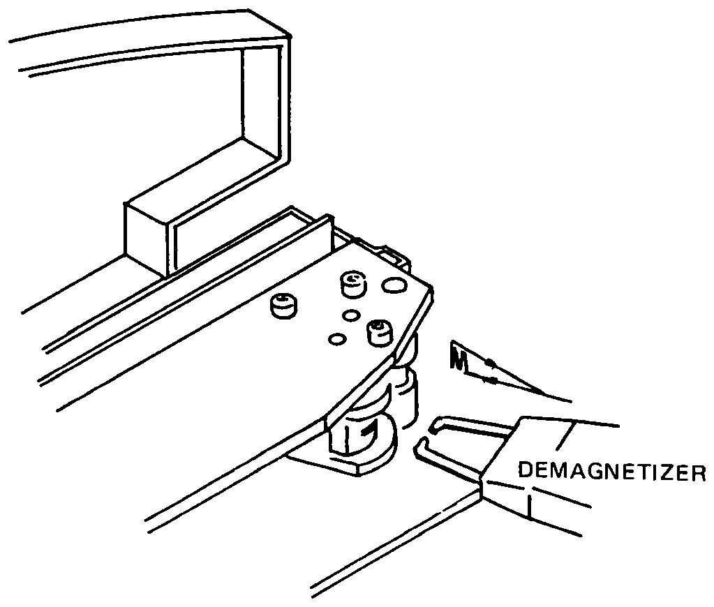 ⤢ zoomLine drawing of a hand-held demagnetizer being brought close to a head stack on the tape transport.
Fig. 4-2 Demagnetizing
4.2.3 LUBRICATION↑ TOP
The only component requiring lubrication is the capstan.
Lubricate the capstan every four months, or after each 1,000 hrs. of operation (whichever occurs first), or as required using the recommended lubricating oil (Table 4-1). For lubrication, proceed as follows, referring to Fig. 4-3:
(1) Remove the pinch roller cap by turning the cross-head screw counterclockwise.
(2) Remove the pinch roller from the pinch roller shaft.
(3) Remove two screws attaching the head housing cover to the tape deck. Remove the head housing cover.
(4) Remove three screws that hold the lower head cover (skirt) to the deck panel. Remove the cover.
(5) Remove the metal dust cap from the capstan shaft by turning it counterclockwise.
(6) The felt collar should now be visible. Apply two or three drops of oil onto this felt collar. Please do not overlubricate.
(7) Wipe off any excess oil and replace the dust cap. Also replace pinch roller and pinch roller cap after replacing lower head cover (skirt) and head housing cover.
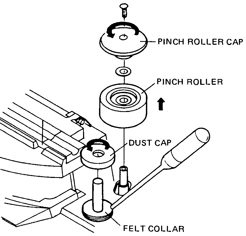 ⤢ zoomExploded line drawing of the capstan's pinch roller cap, pinch roller, dust cap, and felt collar stacked in assembly order.
Fig. 4-3 Lubrication
4.3 ELECTRONIC TRIMMING↑ TOP
Electronic trimming consists of setting the record bias, and setting the record equalization and record level. Note that the reproduction adjustments must be performed before making the recording adjustments. These electronic adjustments should be performed at regularly scheduled intervals, and when changing from one type of recording tape to another.
4.3.1 RECORD BIAS ADJUSTMENT↑ TOP
For optimum performance, biasing should be done using the type of tape that will normally be used. To set the bias level, carry out the following procedure for each channel.
(1) Thread bulk-erased tape on to the recorder.
(2) Set the SRL calibration switch to the SRL position. Set the SPEED switch to the "7-1/2" position.
(3) Start the tape in the record mode.
(4) Press the 1 kHz TEST OSC pushbutton and set the record level control for a 0 reading on the VU meters.
(5) Adjust the RECORD BIAS adjustment trim pot for a maximum reading on the VU meters.
4.3.2 RECORD LEVEL ADJUSTMENT↑ TOP
(1) Set the Record level switch to the "H", "M", or "L" position according to the tape being used or the equalization standard.
(2) Thread bulk-erased tape on to the recorder.
(3) Set the SRL calibration switch to the "SRL" position and the Monitor switch to the "SOURCE" position.
(4) While pressing the 1 kHz TEST OSC pushbutton, adjust the line input levels so that the VU meters indicate 0 VU.
(5) Change the mode of the Monitor switch from "SOURCE" to "TAPE".
(6) Start the tape in the record mode, and adjust the appropriate RECORD LEVEL adjustment trim pot so that the VU meter indicates 0 VU.
4.3.3 RECORD EQUALIZATION ADJUSTMENT↑ TOP
Set the record equalization for each speed and each channel as follows:
(1) Thread bulk-erased tape on to the recorder.
(2) Connect an audio oscillator to the INPUT of the recorder and set the oscillator's frequency to 1 kHz.
(3) Set the SRL switch to the "SRL" position.
(4) Start the tape in the record mode.
(5) For the 15 ips tape speed, adjust the record levels so that the VU meters indicate 0 VU. For the 3-3/4 and 7-1/2 ips tape speeds, set the record levels so that the VU meters indicate -10 VU. Next, set the SRL switch to its normal position and adjust the OUTPUT level controls so that the VU meters indicate 0 VU.
(6) Change the audio oscillator's output to 10 kHz.
(7) As a preliminary setting, adjust the appropriate low or high speed equalizer so that the VU meters indicate 0 VU.
(8) Check the response above and below 10 kHz and trim the record equalizer for the response desired.
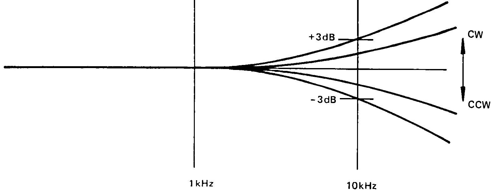 ⤢ zoomFrequency-response graph with curves fanning out above and below 1 kHz and 10 kHz gridlines, bounded by plus and minus 3 dB reference lines.
Fig. 4-4 Record Equalization Adjustment