MX-5050 BII and MKIII-2 Alignment Procedures — Digital Edition · Part 4 · scan pages 21-25
Head Alignment Procedures
4.0 Head Alignment Procedures↑ TOP
PERFORM THIS PROCEDURE ONLY AFTER REPLACING HEADS
This procedure describes the adjustment of Head Height, Zenith, Azimuth, and Wrap.
Adjustment of head height determines the location of the actual recording tracks in relation to the edges of the tape.
The head zenith adjustment sets the face of the head to be absolutely parallel with the plane of the tape. When the zenith is correctly adjusted, the amount of tape contact is the same for all channels of the head.
Adjustment of head azimuth makes the head gaps perpendicular to the tape travel, insuring that the tracks are in phase.
Head wrap determines the location and amount of head penetration into the tape. Correct adjustment insures that the head gap is centered on the tape, so that as the head wears, the frequency response will remain consistant, throughout the life of the head.
HEAD ADJUSTMENT SCREWS (Refer to Fig. 10)
- Socket head screws labeled "T" adjust zenith when the bottom of the head is to be moved in or out.
- Socket head screws labeled "H" adjust zenith when the top of the head is to be moved in or out.
- Adjust "T" and "H" screws simultaneously for head height adjustment.
- Socket head screws labeled "A" adjust the azimuth of the head.
- Phillips head screws labeled "W" attach the head to the Head Base, and are used for wrap (side to side) adjustment.
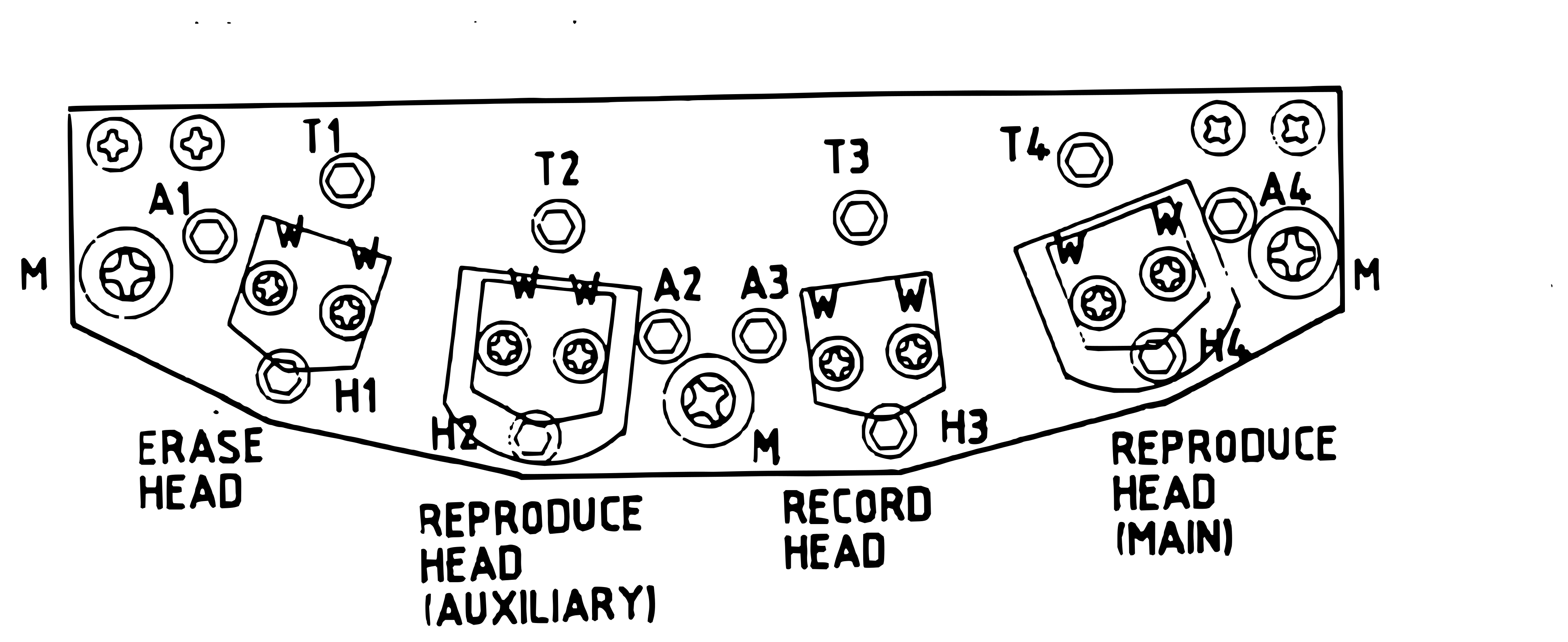 ⤢ zoomFigure 10 Head Adjustment Screws: a plate with a straight top edge and angled lower edge, labeled left to right Erase Head, Reproduce Head (Auxiliary), Record Head, and Reproduce Head (Main); screws T1–T4, A1–A4, and H1–H4, one numbered set per head; two screws labeled W on each head's bracket; large screws labeled M at the left end, right end, and lower center; two unlabeled screws in each top corner
- Phillips head screws labeled "M" attach the head assembly to the machine.
4.1 Head Height and Zenith Adjustment↑ TOP
- Position the machine upside down on the workbench, with the reels hanging over the edge, so they can turn freely.
- Apply Power to the machine and thread it with waste tape (tape which can be discarded after this use). Select 15 ips and the Reel Size appropriate for the reels in use.
- Pull the tape away from the heads, and apply a thin, even, layer of Head Ink (or dry erase marker) to the face of the Reproduce Head. Carefully place the tape back in its normal position. NOTE: Make sure the machine is not in Cue mode.
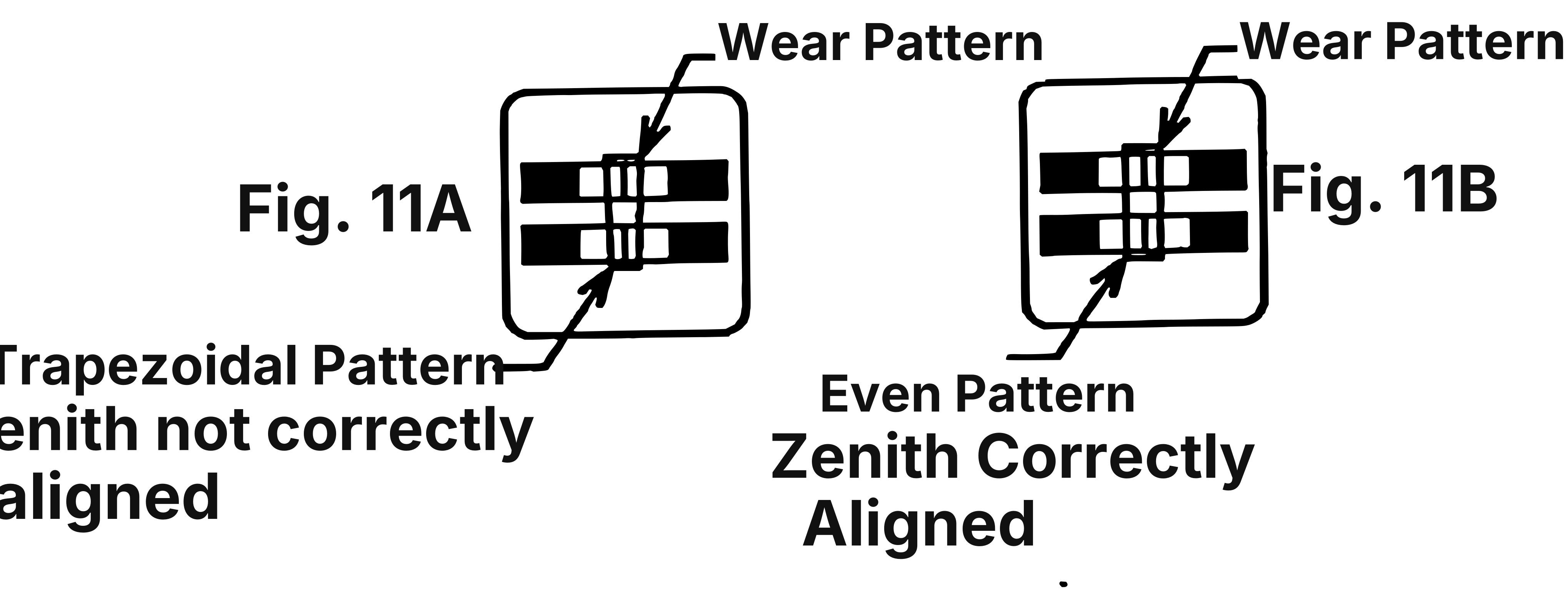 ⤢ zoomFigure 11 Zenith Adjustment Wear Patterns: two square diagrams side by side, each with two dark horizontal bars, each bar with pale rectangles at its middle, and a narrow outlined vertical band crossing both bars; an arrow labeled Wear Pattern and a leader from the panel caption point to that band; in Fig. 11A the band leans (slanted sides), captioned Trapezoidal Pattern, Zenith not correctly aligned; in Fig. 11B the band is upright and parallel-sided, captioned Even Pattern, Zenith Correctly Aligned
-
Place the machine in Play for 10 seconds then Stop the tape.
-
Carefully pull the tape away from the heads. Shine the high intensity lamp onto the heads and use the white card as a reflector to inspect the wear pattern on the face of the Reproduce head. The tape will have removed the marking ink from a small area on the head, as shown in Figure 11.
-
If the wear pattern does not resemble the one shown in Figure 11B, then the Reproduce Head requires adjustment. Figure 11A shows a head with a trapezoidal wear pattern, which indicates that the head height is correct but that the zenith must be adjusted.
If the trapezoidal wear pattern is as shown in Figure 11A, then turn screw T4 (in Figure 10) counterclockwise to bring the lower portion of the head forward.
If the trapezoidal wear pattern is inverted from that shown in Figure 11A, then turn screw T4 (in Figure 10) clockwise to bring the top of the head forward.
-
Repeat Steps 3 through 6 until the wear pattern is symmetrical and approximately the same width at top and bottom.
-
Once the wear pattern is symmetrical, repeat Steps 3 - 6 and inspect the wear pattern for correct head height adjustment. The pattern should be centered over the pole pieces of the head, as shown in Figure 12. If necessary adjust screws T4, H4, and A4 (in Figure 10) simultaneously, and by the same amount, until the wear pattern is correct. If the wear pattern is high on the pole pieces, then the head is too low. In that case turn screws T4, H4, and A4 clockwise until the correct wear pattern is obtained.
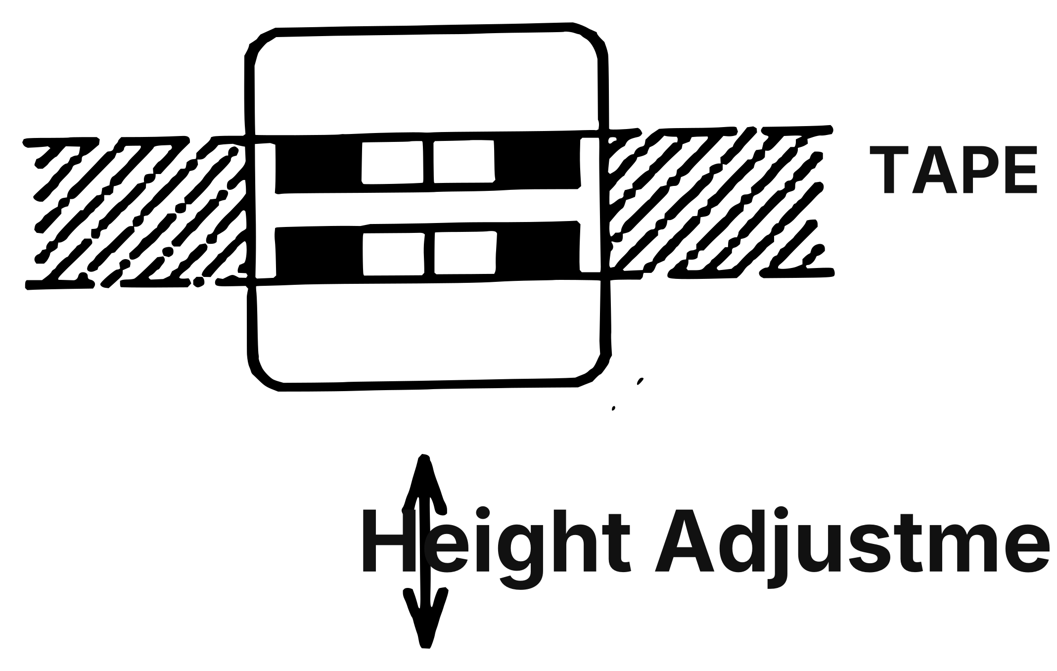 ⤢ zoomFigure 12 Head Height Adjustment: a rounded rectangle crossed by a hatched band labeled TAPE; inside the rectangle two dark horizontal bars, each with two pale squares at the centre; below, a double-headed vertical arrow labeled Height Adjustment
Remember that each time that an adjustment is made, you must re-ink the head and play the tape to create a new wear pattern!
- Repeat the entire procedure for each head in the head Assembly.
4.2 Head Wrap and Azimuth Adjustment↑ TOP
- Clean and demagnetize the heads, guides, and rollers carefully.
- Thread the machine with the 7-1/2 ips Fast Sweep Tape, select 7-1/2 ips, Repro Monitor, and the appropriate reel size. Apply Power to the machine.
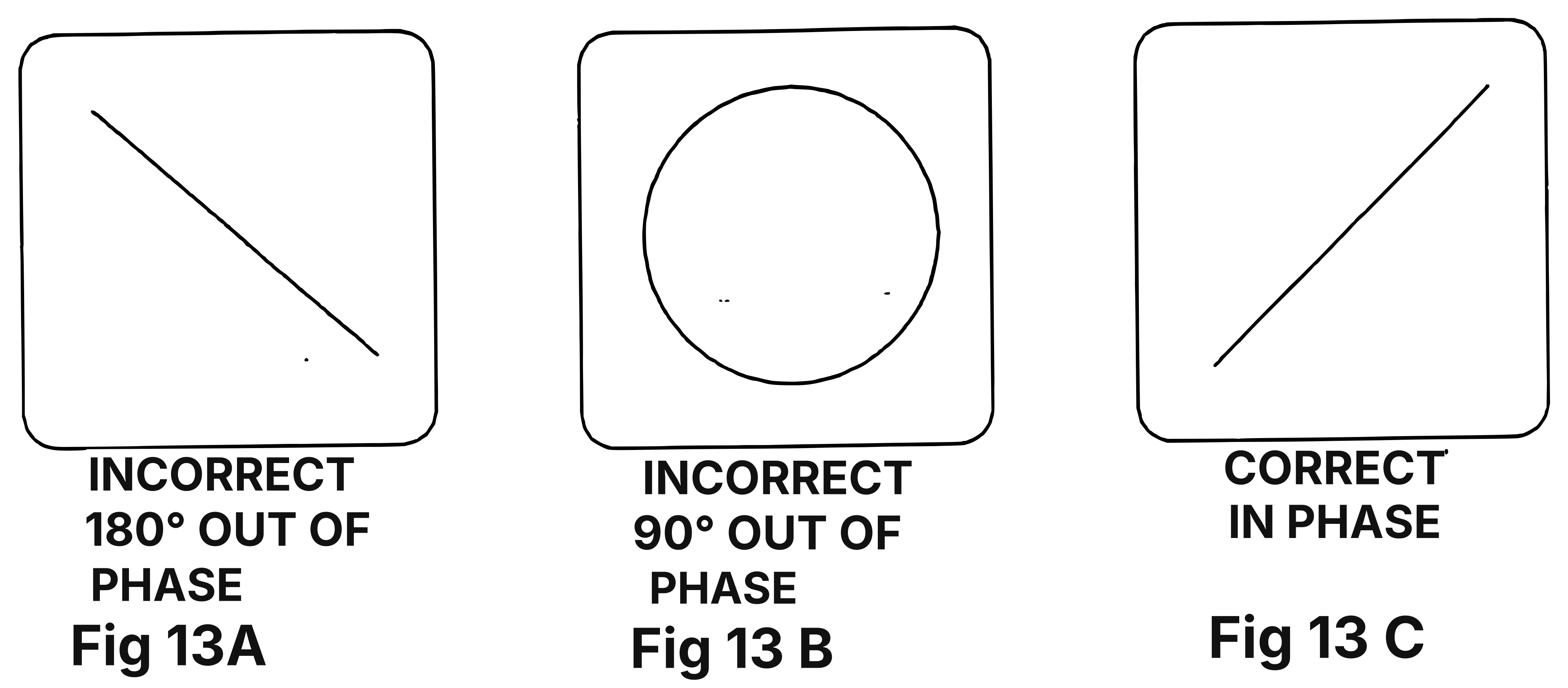 ⤢ zoomFigure 13 Azimuth Adjustment Oscilloscope Displays: three square oscilloscope-screen diagrams side by side; the left one shows a line sloping down to the right, captioned INCORRECT, 180° OUT OF PHASE, Fig 13A; the center one shows a circle, captioned INCORRECT, 90° OUT OF PHASE, Fig 13 B; the right one shows a line sloping up to the right, captioned CORRECT, IN PHASE, Fig 13 C
- Connect the Audio Outputs to the AC Voltmeter and to the X and Y inputs of the Oscilloscope. Set the oscilloscope controls to produce lissajous figures. NOTE: On 4 and 8 channel machines, use the outside tracks i.e., 1 and 4 or 1 and 8.
- Place the machine in Play mode. Adjust the screw marked A4 in Figure 10 until the oscilloscope display looks like Figure 13C.
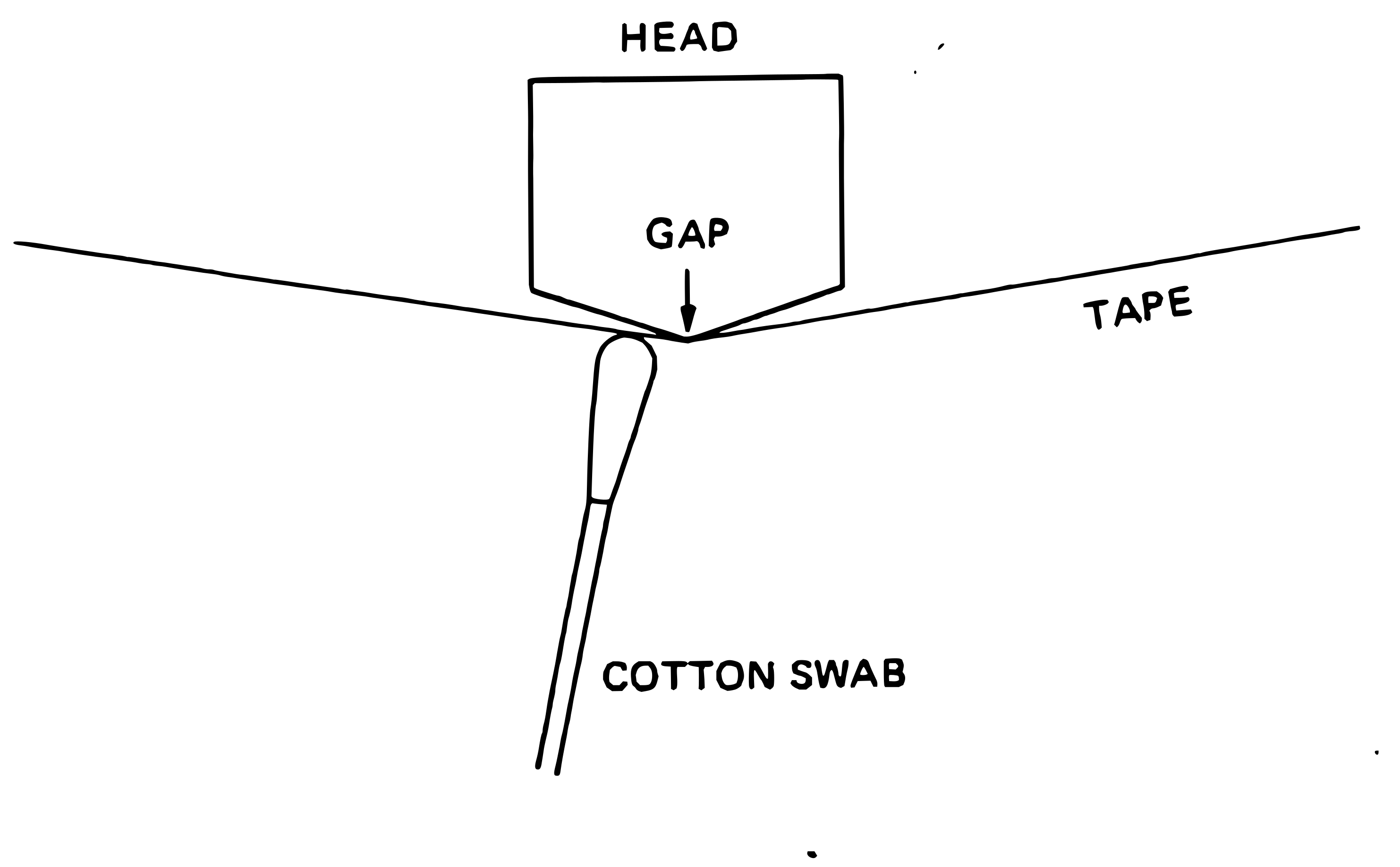 ⤢ zoomFigure 14 Tape Wrap Test Method: a block labeled HEAD with a pointed underside; an arrow labeled GAP points to its tip; a line labeled TAPE runs to that tip from each side in a shallow V; a cotton swab labeled COTTON SWAB touches the tape just left of the tip
- When the Azimuth is correctly adjusted, set the oscilloscope controls so that the entire Fast Sweep burst from both channels are displayed.
- While the tape is playing, gently press on the tape with a cotton swab on first one side of the gap, and then the other side of the gap, while observing the AC Voltmeter and Oscilloscope.
- If the level increases when you press on the Left side of the gap, then loosen the screws marked "W" in Figure 10 slightly, and turn the head slightly to the Left. Try to loosen both "W" screws by the same amount to maintain the Head Azimuth. If the level increased when you pressed on the right side of the Gap, then turn the head to the right.
- Tighten the screws and repeat until there is no level increase when touching the tape on either side of the gap.
- Repeat the Azimuth adjustment in Steps 3 and 4 to confirm that it was not changed during the wrap adjustment.