MX-5050 BII and MKIII-2 Alignment Procedures — Digital Edition · Part 3 · scan pages 8-16,18-21
Audio Channel Reproduce and Record Alignment
3.0 AUDIO CHANNEL REPRODUCE AND RECORD ALIGNMENT↑ TOP
The Audio Alignment procedures are identical for the MX-5050 BII and the MX-5050 MkIII-2 Tape Recorders. The machines differ only in the location of the Amplifier assembly.
If you are aligning an MX-5050 BII, then perform the procedure in Section 3.1 and then perform the adjustments in Section 3.3.
If you are aligning an MX-5050 MkIII-2, then perform the procedure in Section 3.2 then continue with the adjustments in Section 3.3.
3.1 ACCESS TO THE MX-5050 BII AMPLIFIER↑ TOP
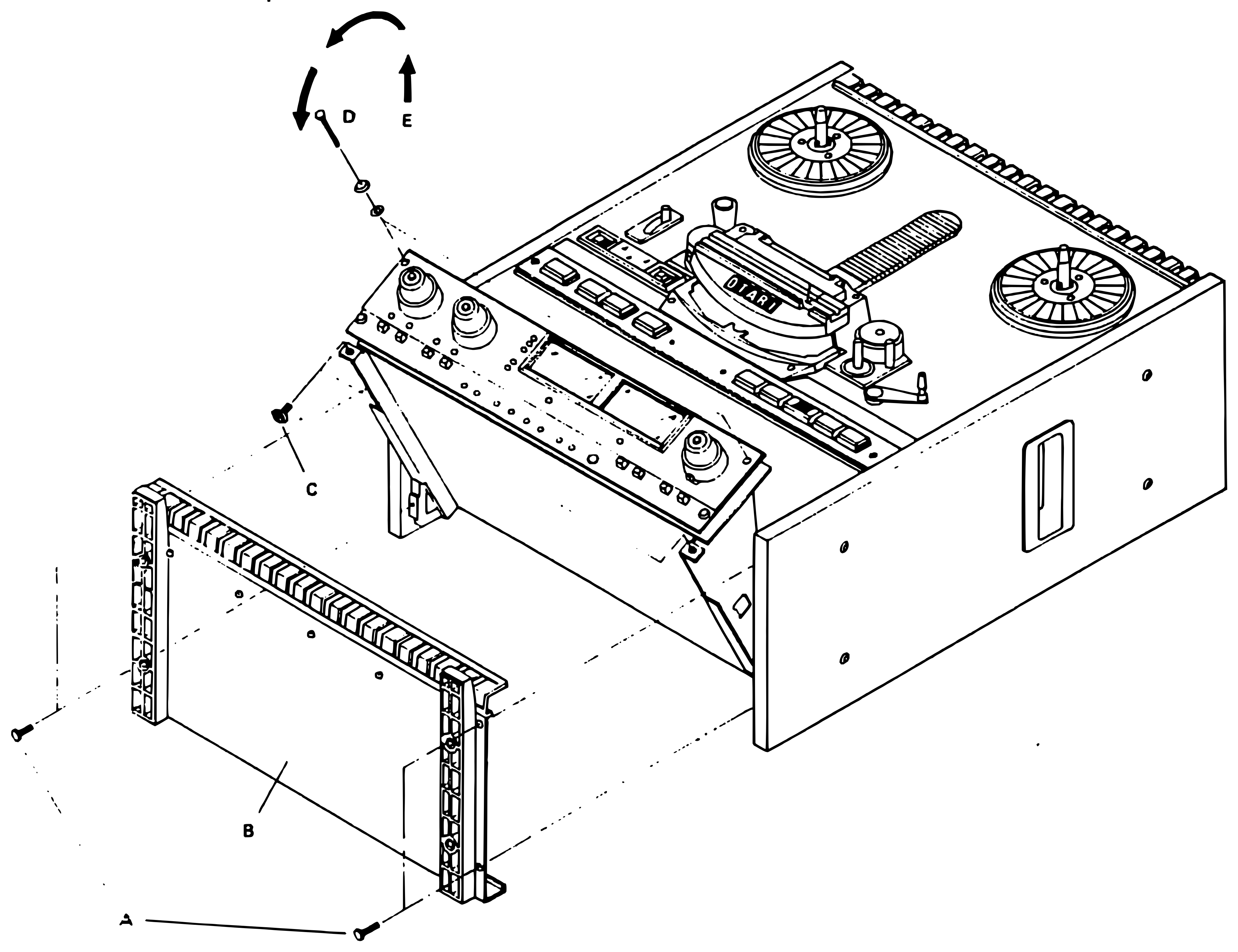 ⤢ zoomFigure 6 Opening the Bottom Panel: the machine viewed upright from above front-left, showing the reels, head block, and meter/amplifier panel, with the bottom panel (B) pulled away below along dash-dot lines, two screws (A), screw C by the amplifier panel, screw D with two washers, a curved arrow, and an upward arrow labelled E
To gain access to the Amplifier;
- Place the machine on its back.
- Remove the 4 screws marked "A" in Figure 6 and remove the bottom panel.
- Remove the 2 screws marked "C" and the 2 screws marked "D".
3.2 ACCESS TO THE MkIII-2 AMPLIFIER↑ TOP
To gain access to the amplifier:
- Remove the front screw, on each side, which attaches the Amplifier assembly to the Side Panels.
- Loosen the rear screw on each side to allow the Amplifier assembly to be pivoted up to give access to the bottom.
- After pivoting up the Amplifier assembly, tighten the rear screws to hold it in position.
- Remove the two screws which attach the bottom panel to the Amplifier assembly.
- Remove the 4 screws which attach the top panel to the Amplifier assembly.
3.3 REPRODUCE ALIGNMENT FOR BII AND MkIII-2↑ TOP
If the machine is to be used primarily at 15 ips, perform the following 15 ips Reproduce Alignment procedure. If the machine is to be used primarily at 7-1/2 ips, perform the adjustments in Section 3.2.2. This is necessary because the machine does not have separate Repro Level controls for each speed.
3.3.1 Reproduce Head Azimuth Alignment↑ TOP
NOTE: Reproduce Head Azimuth alignment for Full-Track machines is performed by adjusting the Full-Track Reproduce head for maximum output while playing the 10 kHz portion of the Reproduce Alignment tape, and then adjusting again using the 16 kHz portion of the tape.
- TurnOff the power to the machine.
- Clean and demagnetize the Heads, Lifters, and Tape Guides. Turn On the power to the machine.
- Thread the machine with the 15 ips Reproduce Alignment Tape.
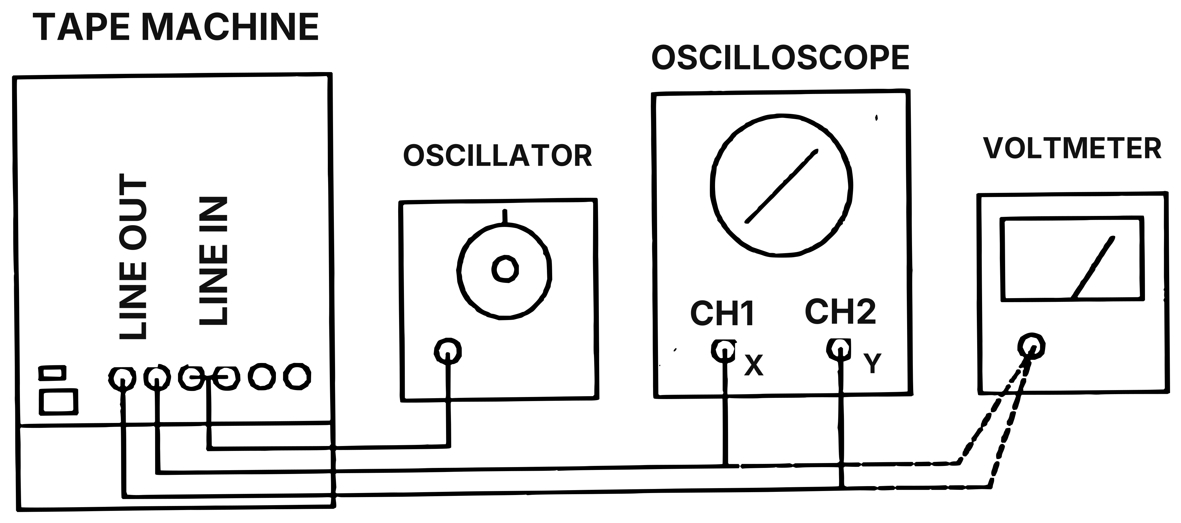 ⤢ zoomFigure 7 Azimuth Alignment Measurement Method: a block diagram of a tape machine's LINE OUT and LINE IN jacks wired to an oscillator, an oscilloscope, and a voltmeter — LINE IN goes to the oscillator, the two LINE OUT jacks go to the oscilloscope's CH1 (X) and CH2 (Y) inputs (whose screen shows a diagonal reference line), and two dashed lines branch from the LINE OUT-CH1/CH2 leads to the voltmeter's single input jack
- Set the REEL SIZE selector to the Large position, set the SPEED selector to the High (15 ips) position, and set the SOURCE/TAPE selectors to the Tape position. (On MkIII-2 machines the SOURCE/TAPE selectors are located on the overbridge). Set the P.B. HEAD switch, located under the Head Cover, to the position for the primary Repro head.
- Connect one oscilloscope input channel to the CH 1 LINE OUTPUT connector on the rear panel. Connect the other oscilloscope input channel to the CH 2 LINE OUTPUT connector. Configure the oscilloscope to display the input waveforms as a "lissajous" pattern using the X-Y display function.
- Turn ON the power to the machine. Adjust the oscilloscope controls so that both signals have equal amplitude when displayed.
- Locate and play the 1 kHz portion of the Reproduce Alignment tape and adjust the screw marked A4 in Figure 8, until the pattern on the oscilloscope becomes a straight line at a 45 degree angle as shown in Figure 7.
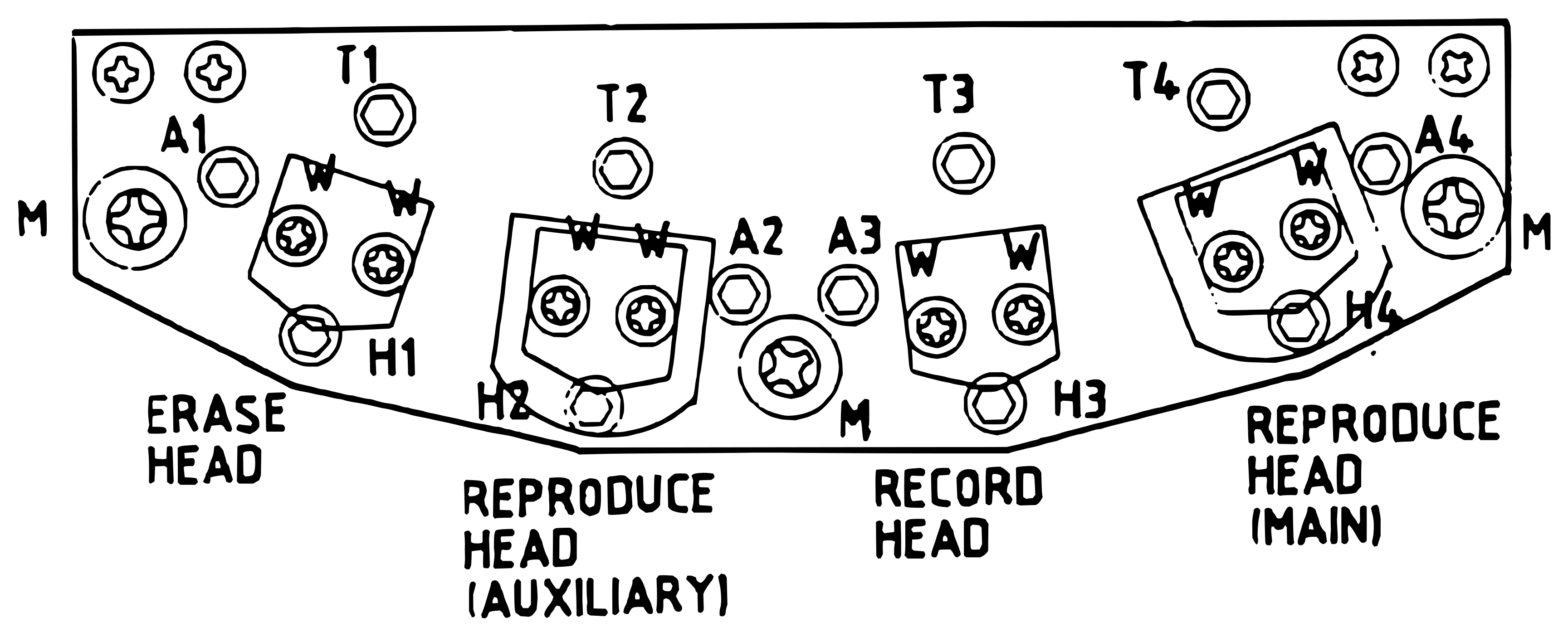 ⤢ zoomFigure 8 Head Assembly Adjustments: the head-assembly mounting bar viewed from above, showing four head positions — Erase Head, Reproduce Head (Auxiliary), Record Head, and Reproduce Head (Main) — each bracket with two W screws and a circled A screw (A1-A4), circled T screws (T1-T4) along the top edge, circled H screws (H1-H4) along the bottom edge, and circled M mounting screws at the two ends and at center
- Play each increasing frequency section of the Reproduce Alignment tape (2 kHz, 4 kHz, 8 kHz, 10 kHz, 12.5 kHz, 16 kHz, and 20 kHz) and adjust the screw marked A4 until the pattern on the oscilloscope becomes a straight line at a 45 degree angle, at each frequency, as shown in Figure 7.
- Repeat Steps 1 through 8 for the secondary Reproduce Head (the head in position 2 on the Head Assembly), using screw A2 for adjustment.
NOTE: Less and less adjustment is required as the frequency increases to cause the oscilloscope pattern to become correctly displayed. At higher frequencies, it will be impossible to achieve a perfectly straight line, some amount of jitter is normal. Adjust the azimuth screw until the best possible result is obtained.
3.3.2 15 ips Reproduce Alignment↑ TOP
NOTE: Perform the Reproduce Azimuth Alignment procedure in Section 3.3.1 before performing the following adjustments.
- Turn Off the power to the machine, and connect the millivoltmeter to the rear panel Line Output connector.
- Clean and demagnetize the Heads, Lifters, and Tape Guides.
- Connect the power cord, and turn On the power to the machine.
- Set the REEL SIZE selector to the Large Reel position, set the TAPE SPEED selector to the High (15 ips) position, and set the SOURCE/TAPE selector to Tape monitor.
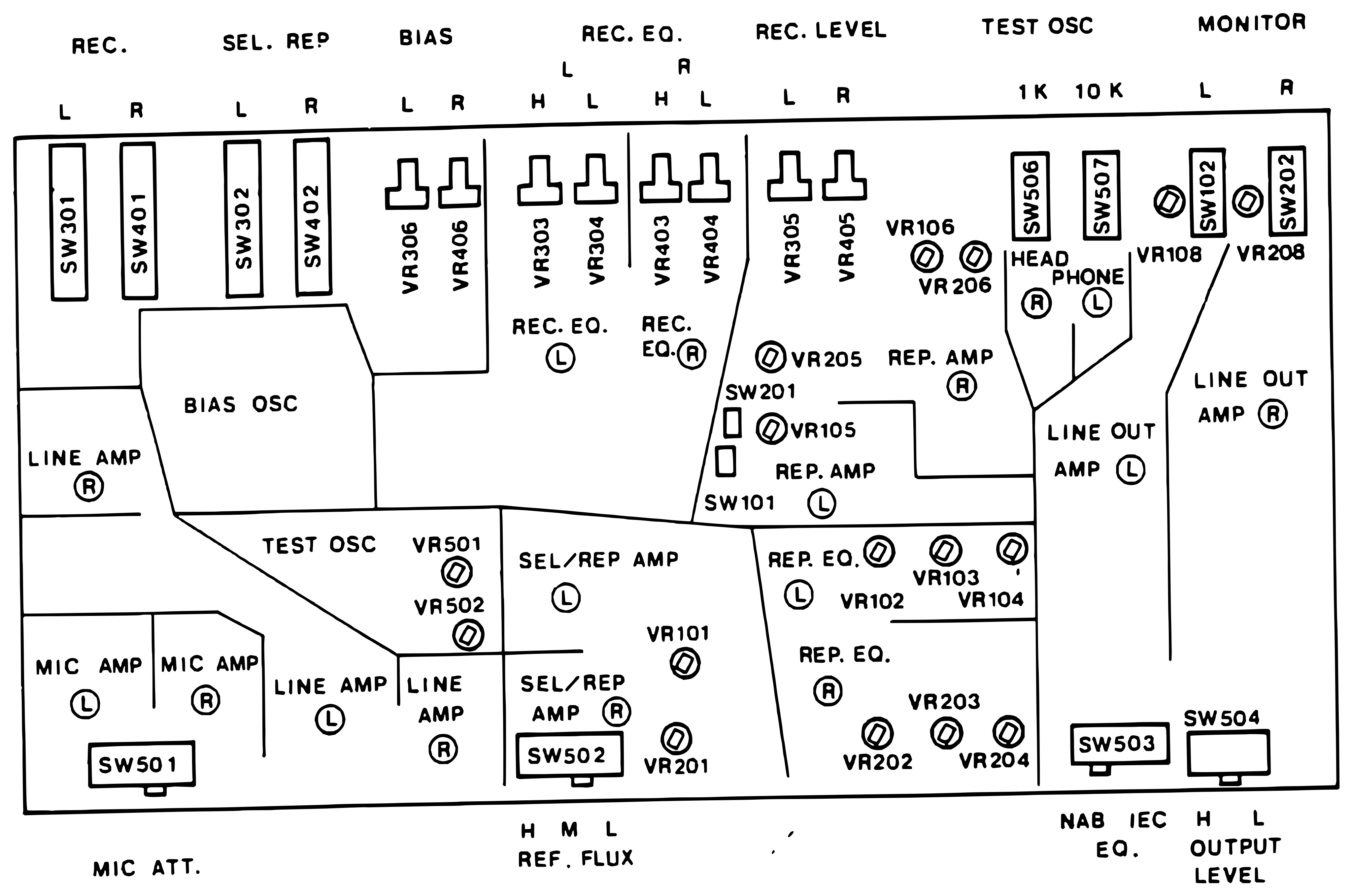 ⤢ zoomFigure 9 Location of Trimmers on the Audio PCB: the Audio PCB laid out in function blocks (BIAS OSC, TEST OSC, LINE AMP, MIC AMP, SEL/REP AMP, REP. AMP, REP. EQ., LINE OUT AMP) under the group headings REC., SEL. REP, BIAS, REC. EQ., REC. LEVEL, TEST OSC, and MONITOR, with switches SW301/SW401, SW302/SW402, SW501, SW502, SW101/SW201, SW506/SW507, SW102/SW202, and SW503/SW504, trimmers VR306/VR406, VR303/VR304, VR403/VR404, VR305/VR405, VR106/VR206, VR105/VR205, VR501/VR502, VR101/VR201, VR102/VR103/VR104, VR202/VR203/VR204, and VR108/VR208, and the bottom labels MIC ATT., REF. FLUX, EQ., and OUTPUT LEVEL
-
Set the SRL slide switch to the SRL position (the SRL indicator will become illuminated).
-
On the rear panel, set the OUTPUT LEVEL switch to the High position, set the EQUALIZATION switch to the NAB position, and set the REF FLUX switch to the MID position.
-
Flip up the Head Cover, and set the Repro Head selector switch to the appropriate position:
1/2 Tr Rec/Repro - 2T position
1/4 Tr Rec/Repro - 4T position
Full Tr Rec/Repro - FT position
NOTE: Reproduce Alignment of Full Track machines requires that only the CH 1 trimmers be adjusted.
- Thread the machine with the 15 ips Reproduce Alignment Tape and locate the 1 kHz tone at the Reference Level.
- While playing the 1 kHz portion of the tape, adjust VR 106 (Repro SRL level) for +4 dBm at the rear panel Output connector.
- Repeat Step 9 for Channel 2, adjusting VR 206 for +4 dBm at the Channel 2 rear panel Output connector.
- Play the 10 kHz portion of the tape and adjust VR 102 (High Speed High Frequency Eq) for +4 dBm at the Channel 1 Output connector.
- Repeat Step 11 for Channel 2, adjusting VR 202 for +4 dBm at the Channel 2 rear panel Output connector.
- Play the remaining tones (from 10 kHz to 20 kHz) and make sure that the output level does not change more than -2 dB up to 20 kHz.
- On the front panel (Overbridge on MkIII-2), set the SEL- REP switches to the On (Sel-Rep) position.
- Play the 1 kHz tone at Reference level and adjust VR 101 for +4 dBm at the Channel 1 Output connector.
- Repeat Step 15 for Channel 2, adjusting VR 201 for +4 dBm at the Channel 2 Output connector.
3.3.3 7-1/2 ips Reproduce Alignment↑ TOP
NOTE: Perform the Reproduce Azimuth Alignment procedure in Section 3.3.1 before performing the following adjustments.
-
With the Power to the machine turned Off, clean and demagnetize the Heads, Lifters, and Tape Guides.
-
TurnOn the power to the machine, thread the machine with the 7-1/2 ips Reproduce Alignment Tape and locate the 1 kHz tone at the Reference Level. NOTE: Make sure the SOURCE/TAPE switches are in the Tape position, and the SEL-REP switches are in the Off position.
-
On the rear panel, set the OUTPUT LEVEL switch to the High position, set the EQUALIZATION switch to the NAB position, and set the REF FLUX switch to the Mid position.
-
Flip up the Head Cover, and set the Repro Head selector switch to the appropriate position:
1/2 Tr Rec/Repro - 2T position
1/4 Tr Rec/Repro - 4T position
Full Tr Rec/Repro - FT position
NOTE: Reproduce Alignment of Full Track machines requires that only the CH 1 trimmers be adjusted.
- While playing the 1 kHz at Reference Level portion of the tape, adjust VR 106 (Repro SRL level) for +4 dBm at the rear panel Output connector.
- Repeat Step 5 for Channel 2, adjusting VR 206 for +4 dBm at the Channel 2 rear panel Output connector.
- Play the 10 kHz portion of the tape and adjust VR 103 (Low Speed High Frequency Eq) for -6 dBm at the Channel 1 Output connector. (+4 dBm if the 10 kHz tone is at Reference level).
- Repeat Step 7 for Channel 2, adjusting VR 203 for -6 dBm at the Channel 2 rear panel Output connector.
- Play the remaining tones (from 10 kHz to 20 kHz) and make sure that the output level does not change more than -2 dB up to 16.5 kHz.
- On the front panel, set the SEL-REP switches to the On (Sel-Rep) position.
- Play the 1 kHz tone at Reference level and adjust VR 101 (Sel-Rep Level) for +4 dBm at the Channel 1 Output connector.
- Repeat Step 11 for Channel 2, adjusting VR 201 for +4 dBm at the Channel 2 Output connector.
3.3.4 Peak Indicator Calibration↑ TOP
- Set the SOURCE/TAPE switches to the Source position, and set the oscillator to produce 1 kHz. Adjust the front panel LINE INPUT controls, and the oscillator level control, to produce +16 dBm at the rear panel Line Output connector.
- Adjust VR 701 (Channel 1) and VR 801 (Channel 2) until the PEAK indicators (in each VU Meter) just become illuminated. NOTE: These trimmers are located on the PCB adjacent to the VU Meters inside the Amplifier Assembly. On BII models only it will be necessary to rotate the amplifier assembly down to gain access to these controls.
3.4 RECORD ALIGNMENTS↑ TOP
NOTE: If Record Alignment is performed at 7-1/2 ips, perform procedures 3.4.3 through 3.4.5 using -6 dBm input level, instead of +4 dBm, to avoid tape saturation.
With the Power OFF:
-
Set the REEL SIZE and SPEED switches to the desired positions. Set the SOURCE/TAPE switches to the Tape position. Set the RECORD switches for both channels to the On position.
-
On the rear panel, set the REF FLUX switch to the Mid position. Set the OUTPUT LEVEL switch to the High position, and set the EQUALIZATION switch to the NAB position.
-
Clean the heads, lifters, and tape guides carefully with 70% isopropyl alcohol and cotton swabs.
-
Demagnetize the heads, lifters, and tape guides.
-
Thread the machine with a full 10.5" reel of virgin Ampex 456 recording tape.
-
Connect the oscillator to the Channel 1 rear panel INPUT connector.
-
Connect the AC millivoltmeter to the Channel 1 rear panel OUTPUT connector.
Connect the Power cord and turn On the power to the machine.
3.4.1 Bias Adjustment↑ TOP
- Set the SOURCE/TAPE switch to the Source position and adjust the oscillator to produce 10 kHz at approximately -3 VU (for 7-1/2 ips use 5 kHz at -5 VU). (Any level up to 0 VU can be used for Bias adjustment at 15 ips, up to -3 VU at 7- 1/2 ips).
- SetVR 306 fully counterclockwise.
- Press the CH 1 and CH 2 RECORD buttons. The adjacent LEDs will flash.
- Place the machine in Record mode. Set the SOURCE/TAPE switch to the Tape position.
- Turn VR 306 (Bias Level) clockwise until the signal level on the millivoltmeter reaches a peak, then continue turning VR 306 clockwise until the level decreases 3.5 dB below the peak level. (This sets the bias for 3.5 dB "overbias").
- Connect the millivoltmeter and oscillator to the Channel 2 Output and Input, respectively.
- Set VR 406 fully counterclockwise. Perform Step 11 using VR 406.
MX-5050 SERIES BIAS TABLE↑ TOP
| AGFA 468 | AMPEX 456 | SCOTCH 226 | SCOTCH 250 | SCOTCH 806 | SCOTCH 808 | ||
|---|---|---|---|---|---|---|---|
| BII | 15 | +2 | +3 | +3 | +2 | +2.5 | +5.5 |
| BII | 7.5 | +2 | +3 | +3 | +2 | +3 | +6 |
| BII | 3.75 | +1 | +2.5 | +2 | +1 | +1.5 | +4 |
| III-2 | 15 | +3 | +3 | +3 | +3 | +3 | +6 |
| III-2 | 7.5 | +3 | +3 | +3 | +3 | +3 | +6 |
| III-2 | 3.75 | +1 | +3 | +2 | +1 | +1.5 | +3.5 |
| BQII | 15 | +2.5 | +3 | +3 | +3 | +3 | +2.5 |
| BQII | 7.5 | +3 | +3.5 | +3 | +3 | +3.5 | +2.5 |
| III-4 | 15 | +3 | +4 | +3 | +3 | +3 | N/A |
| III-4 | 7.5 | +3 | +4 | +3 | +3 | +4 | N/A |
| III-8 | 15 | +3 | +3 | +3 | +3 | +3 | N/A |
| III-8 | 7.5 | +3.5 | +3 | +3 | +2.5 | +3.5 | N/A |
| BIAS FREQ | NOMINAL RECORD LEVEL | |
|---|---|---|
| 15 ips | 10 kHz | 0 dB |
| 7.5 ips | 5 kHz | -10 dB |
| 3.75 ips | 1 kHz | -20 dB |
3.4.2 Record Head Azimuth Alignment↑ TOP
NOTE: Record Head Azimuth alignment on Full Track machines requires that the Record Head Azimuth be adjusted for maximum output while monitoring from the Full Track Reproduce head while recording a 1 kHz signal, and then repeating the adjustment at 10 kHz and 16 kHz.
-
Connect the oscillator to both CH 1 and CH 2 LINE INPUT connectors, in parallel. Set the oscillator to produce 1 kHz at +4 dBm (-6 dBm for alignment at 7-1/2 ips).
-
Connect one oscilloscope input channel to the CH 1 LINE OUTPUT connector on the rear panel. Connect the other oscilloscope input channel to the CH 2 LINE OUTPUT connector. Configure the oscilloscope to display the input waveforms as a "lissajous" pattern using the X-Y display function.
Adjust the oscilloscope controls so that both signals have equal amplitude when displayed with the machine in SOURCE monitor.
-
Set the SOURCE/TAPE selectors to the Tape position.
-
Thread the machine with a full reel of blank tape.
-
Place the machine in Record mode.
-
Adjust the screw marked A3 in Figure 7 until the pattern on the oscilloscope display becomes a straight line at a 45 degree angle as shown in Figure 8.
-
Change the frequency setting of the oscillator to 10 kHz, and repeat Step 6.
-
Change the frequency setting of the oscillator to 18 kHz, and repeat Step 6.
-
Stop the tape.
NOTE: Less and less adjustment is required as the frequency increases to cause the oscilloscope pattern to become correctly displayed. At higher frequencies, it will be impossible to achieve a perfectly straight line, some amount of jitter is normal. Adjust the azimuth screw until the best possible result is obtained.
3.4.3 Input and Record Level Calibration↑ TOP
- Connect the Oscillator to the Channel 1 Input, and connect the millivoltmeter to the Channel 1 Output.
- Set the SOURCE/TAPE switches to Source. On the rear panel, set the REF FLUX switch to the Mid position. Set the OUTPUT LEVEL switch to the High position, and set the EQUALIZATION switch to the NAB position.
- Set the oscillator to produce 1 kHz at +4 dBm at the machine input.
- Adjust the front panel Channel 1 LINE INPUT control to the "11 o'clock" position.
- Adjust VR 108 until the millivoltmeter indicates +4 dBm.
- Connect the Oscillator to the Channel 2 Input, and connect the millivoltmeter to the Channel 2 Output.
- Adjust the front panel Channel 2 LINE INPUT control to the "11 o'clock" position.
- Adjust VR 208 until the millivoltmeter indicates +4 dBm.
- Set the SOURCE/TAPE switches to Tape position.
- Place the machine in Record mode, and adjust VR 405 (Rec Level) until the millivoltmeter indicates +4 dBm.
- Connect the Oscillator to the Channel 1 Input, and connect the millivoltmeter to the Channel 1 Output.
- Place the machine in Record mode, and adjust VR 305 (Rec Level) until the millivoltmeter indicates +4 dBm.
3.4.4 High Frequency Equalization Adjustment↑ TOP
- While still in Record mode from Section 3.4.3, set the oscillator to produce 10 kHz at +4 dBm, and connect it to the Channel 1 Input connector. Connect the millivoltmeter to the Channel 1 Output connector.
- Make sure the SOURCE/TAPE switches are still set for Tape monitor mode and adjust VR 303 (High Speed High Frequency Rec Eq) until the millivoltmeter indicates +4 dBm.
- Sweep the oscillator frequency up to 20 kHz and make sure that the output level does not change more than -2 dB.
- Connect the oscillator and millivoltmeter to Channel 2, and adjust VR 403 until the millivoltmeter indicates +4 dBm.
- Repeat Step 3 for Channel 2.
3.4.5 Low Frequency Compensation Adjustment↑ TOP
NOTE: The LOW COMP trimmers (VR 105/205) have no effect unless the LOW COMP switches SW 101 and SW 201 are set to the On position. These switches are set to the Off position at the OTARI factory.
- Set the oscillator to produce approximately 20 Hz at +4 dBm, and connect it to the Channel 1 Input. Connect the millivoltmeter to the Channel 1 Output.
- Set the LOW COMP switches SW 101 and SW 201 to the On position. NOTE: The LOW COMP switches are located inside the Amplifier Assembly adjacent to the LOW COMP trimmers. On BII models only it will be necessary to rotate the amplifier assembly down to gain access to these switches. Rotate the amplifier assembly back up to its normal position to make the adjustment.
- Set the SOURCE/TAPE monitor switches to the Tape position.
- Press the CH 1 and CH 2 REC buttons, and place the machine into Record mode.
- Manually sweep the oscillator from 20 Hz to 200 Hz and adjust VR 105 (Low Frequency Compensation) for flattest frequency response.
- Connect the oscillator and millivoltmeter to Channel 2.
- Manually sweep the oscillator from 20 Hz to 200 Hz and adjust VR 205 for flattest frequency response.
3.4.6 Oscillator Adjustment↑ TOP
IMPORTANT: The Input and Record Level adjustment in Section 3.4.3 must be performed before performing this adjustment.
NOTE: The internal test oscillator feeds both channels simultaneously, therefore the oscillator adjustment affects both channels.
- Connect the AC millivoltmeter to the rear panel CH 1 LINE OUTPUT connector.
- Press the 1 KHZ - TEST OSC button to activate the internal Test Oscillator.
- Set both front panel LINE INPUT level controls to the "11 o'clock" position.
- Adjust VR 502 until the millivoltmeter indicates +4 dBm.
- Press the 10 KHZ - TEST OSC button to set the internal Test Oscillator to 10 kHz.
- AdjustVR 501 until the millivoltmeter indicates +4 dBm.
This completes the record alignments.