MX-5050 MKIV-2 and BIII-2 Operation and Maintenance Manual — Digital Edition · Part 7 · PDF pages 78-88
Audio Alignment
This section includes the following sub sections.
| 7.1 | Tools and Equipment Required | 7-2 |
| 7.2 | Preliminary Adjustments | 7-3 |
| 7.2.1 | Peak Indicator Level Adjustment | 7-3 |
| 7.2.2 | Test Oscillator Waveform and Level Adjustment | 7-4 |
| 7.3 | Reproduce Adjustments | 7-5 |
| 7.3.1 | Reproduce Head Azimuth Adjustment | 7-5 |
| 7.3.2 | Reproduce Level Adjustment | 7-6 |
| 7.3.3 | Reproduce Equalization Adjustment | 7-7 |
| 7.4 | Record Electronics Adjustments | 7-8 |
| 7.4.1 | Record Bias Level Adjustment | 7-8 |
| 7.4.2 | Record Head Azimuth Adjustment | 7-9 |
| 7.4.3 | Record Level Adjustment | 7-10 |
| 7.4.4 | Record EQ Adjustment | 7-10 |
| 7.4.5 | Low Frequency Reproduce EQ Adjustment | 7-11 |
| 7.4.6 | SEL-REP Level Adjustment | 7-11 |
7.1 Tools and Equipment Required↑ TOP
-
Alignment Tapes suitable for the tape speed most often used. Otari recommends the following Alignment Tapes.
Table 7-1
Reference TapesTape Speed Flux Level MRL* Catalog No. 15 ips 250 nWb/m 21J205 (NAB) 320 nWb/m 21J303 (IEC) 7.5 ips 250 nWb/m 21T204 (NAB) 320 NWb/m 21T302 (IEC) 3.75ips 200 nWb/m 21F101A (NAB, IEC) * Magnetic Reference Laboratories
-
An AC voltmeter calibrated in millivolts and decibels, having a high enough input impedance so as not to load down the circuit under test, and able to display dBm (0dBm = 0.775V)
-
A general purpose dual-trace oscilloscope such as those made by Tektronics, Leader, Hitachi and Hewlett Packard.
-
A sweepable test oscillator capable of generating sine waves at frequencies from 20 Hz to 20 kHz at +4 dBm (or whatever standard operating level is used, e.g., –10 dBm or +6 dBm).
-
A reel of tape of the type normally used for sessions.
-
Hand Tools.
-
A non-magnetic alignment screwdriver with a blade small enough to fit the trimmers on the PCB Assemblies.
-
A tape head demagnetizer (degausser).
-
Pure (90%) isopropyl alcohol, cotton swabs, and lint-free cloth for cleaning the tape path.
CAUTION: Do not use rubbing alcohol, as this can leave water and oil residues, and do not use any other solvent, as it may delaminate the heads.
7.2 Preliminary Adjustments↑ TOP
These adjustments are performed when first receiving the machine, and then again only when an audio component, such as the Heads, is replaced.
7.2.1 Peak Indicator Level Adjustment↑ TOP
NOTE: The PEAK indicator is factory preset to illuminate at a level equivalent to 1040 nWb/m, which corresponds to approximately 3% THD.
- Check the trigger level corresponding to the set Magnetic Reference Flux Level.
Table 7-2
Trigger Level
| Magnetic Ref. Flux Level | Trigger Level |
|---|---|
| 185 nWb/m | Standard Level + 15.0 dB |
| 250 nWb/m | Standard Level + 12.4 dB |
| 320 nWb/m | Standard Level + 11.2 dB |
-
Connect an oscillator to the CH1 INPUT connector, adjust the oscillator so that it generates a sine wave (1kHz) at the trigger level. Confirm that neither of the internal Test Oscillator buttons are pressed.
EXAMPLE: Set the oscillator to +16.4 dBu when the Magnetic Reference Level is 250 nWb/m and the Reference Level is +4 dBu.
-
Set the Monitor button to SOURCE position (not depressed).
-
Adjust VR701 for CH1 and VR801 for CH2 on the VU Meter Amp PCB which is located behind the VU meter so that the peak indicator illuminates at the trigger level.
7.2.2 Test Oscillator Waveform and Level Adjustment↑ TOP
Perform this adjustment after the Level Matching Adjustment (§ 7.2.1) has been completed.
- Set the Monitor button of CH1 to SOURCE position.
- Press the 1kHz TEST OSC button on the AMP Panel.
- Adjust VR502 on the REC/REP AMP PCB Assembly (see Figure 7-1) so that the VU meter indicates 0 VU. Perform the same adjustment to the CH2 REC/REP AMP PCB Assembly.
- Press the 10kHz OSC FREQ button.
- Adjust VR501 so that the VU meter indicates 0VU.
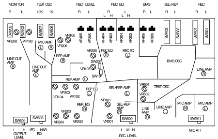 ⤢ zoomFigure 7-1 REC/REP AMP PCB (DIP Side): a PCB layout diagram with seven category headers (MONITOR, TEST OSC, REC. LEVEL, REC. EQ, BIAS, SEL·REP, REC) above a rectangular board outline, each with its own R/L channel column heads (TEST OSC's own pair reading 10K/1K over SW507/SW506; REC. EQ's own pair further split into L/H per channel). Each trimmer (VR) and switch (SW) is shown as a labeled circle or rectangle within its own functional block (LINE OUT AMP, REP.AMP, MIC AMP, BIAS OSC, TEST OSC, SEL·REP AMP, LINE AMP), grouped in L/R channel pairs throughout. Four switch-position legends print along the board's bottom edge: OUTPUT LEVEL L/H (SW504), EQ IEC/NAB (SW503), REC. LEVEL L/M/H (SW502), and MIC ATT (SW501).
Switches and Trimmers on the REC/REP AMP PCB
| SW301 | Record Selection L Ch |
| SW401 | Record Selection R Ch |
| SW302 | SEL/REP Selection LCh |
| SW 402 | SEL/REP Selection R Ch |
| SW 506 | TEST OSC 1kHz |
| SW507 | TEST OSC 10kHz |
| SW102 | Monitor Selection LCh |
| SW202 | Monitor Selection R Ch |
| SW501 | Mic. Attenuator |
| SW502 | Record Level Selection |
| SW503 | EQ(NAB/IEC) Selection |
| SW504 | Output Level Selection |
| VR306 | Bias L CH |
| VR406 | Bias R CH |
| VR303 | REC EQ High Speed L CH |
| VR304 | REC EQ Low Speed L CH |
| VR403 | REC EQ High Speed R CH |
| VR404 | REC EQ Low Speed R CH |
| VR305 | REC Level L CH |
| VR405 | REC Level R CH |
| VR106 | REP SRL Level LCH |
| VR206 | REP SRL Level R CH |
| VR108 | Input Level L CH |
| VR208 | Input Level R CH |
| VR501 | OSC Level (10kHz) |
| VR502 | OSC Level (1kHz) |
| VR101 | SEL-REP Level L CH |
| VR201 | SEL-REP Level R CH |
| VR205 | Low F Comp. R CH |
| SW201 | Low Comp. Selection R Ch |
| VR105 | Low F Comp. L CH |
| SW101 | Low Comp. Selection L Ch |
| VR102 | 15ips REP EQ L CH |
| VR103 | 7.5ips REP EQ L CH |
| VR104 | 3.75ips REP EQ LCH |
| VR202 | 15ips REP EQ RCH |
| VR203 | 7.5ips REP EQ RCH |
| VR204 | 3.75ips REP EQ RCH |
7.3 Reproduce Adjustments↑ TOP
7.3.1 Reproduce Head Azimuth Adjustment↑ TOP
-
Turn off the power to the machine.
-
Clean and demagnetize the Heads, Lifters, and Tape Guides. Turn on the power to the machine.
-
Thread the machine with a 7.5 ips Reproduce Alignment Tape.
-
Set the tape speed to 7.5 ips. Set the RECORD READY button to SAFE position. Press down the Monitor button to TAPE position.
NOTE: Insert the Headphone Plug into the Phone Jack. Adjust the Monitor Level with the Output Level Control Knob.
-
Connect one input channel of the oscilloscope to the CH 1 OUTPUT connector. Connect the other input channel of the oscilloscope to the CH 2 OUTPUT connector. Adjust the oscilloscope to display the input waveforms as a "lissajous" pattern using the X-Y display function (see Figure 7-3).
-
While reproducing the azimuth adjusting section (500 Hz) of the 7.5 ips test tape, adjust the azimuth adjustment screw A3 (see Figure 7-2) so that the lissajous figure becomes a straight line.
-
While reproducing the 16 kHz section of the Test Tape, adjust the azimuth adjustment screw A3 so that the lissajous figure becomes a straight line.
NOTE: Less and less adjustment is required as the frequency increases to cause the oscilloscope pattern to become correctly displayed. At higher frequencies, it will be impossible to achieve a perfectly straight line, some amount of jitter is normal. Adjust the azimuth screw until the best possible result is obtained.
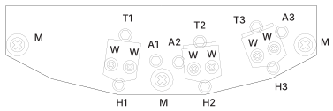 ⤢ zoomFigure 7-2 Head Adjustment Screws: a front view of the head-mounting bracket with the T1/T2/T3 and A1/A2/A3 screws either side of each head stack's paired W mounting screws, the H1/H2/H3 height screws along the bottom edge, and the M guide-post screws at each end.
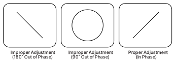 ⤢ zoomFigure 7-3 Wave shape On the Oscilloscope: three rounded-rectangle oscilloscope-display boxes side by side — a steep diagonal line (Improper Adjustment, 180° Out of Phase), a circle (Improper Adjustment, 90° Out of Phase), and a shallower diagonal line (Proper Adjustment, In Phase).
7.3.2 Reproduce Level Adjustment↑ TOP
Perform the following adjustment at the speed most often used.
- Thread the machine with the Reproduce Alignment Tape (Refer to § 7.1). Press down the both Monitor buttons to TAPE position.
- Connect the AC Voltmeter to the CH 1 OUTPUT connector.
- Set the SRL switch to SRL position. Play the 1 kHz at Reference Level portion of the Reproduce Alignment Tape.
- Adjust VR106 (SRL LEVEL) on the REC/REP AMP PCB Assembly so that the AC voltmeter indicates +4 dBu.
- Connect the AC voltmeter to 2 channel OUTPUT connector and repeat Steps 3 and 4 for 2 channel using VR206.
7.3.3 Reproduce Equalization Adjustment↑ TOP
NOTE: In this section, the Reproduce EQ is adjusted. Low Frequency Compensation will be covered in § 7.4.6.
-
Set the SPEED LO/HI switch to the HI position.
-
Thread the 15 ips Reproduce Alignment tape. (For Low Version models, thread 7.5 ips Alignment tape instead.)
-
Set the both RECORD READY buttons of the all channels to the SAFE position. Press down the both Monitor buttons to TAPE position.
-
Connect the AC voltmeter to the CH1 Output connector.
-
Play the 10 kHz portion of the Reproduce Alignment tape and adjust VR 102 for High Speed models (VR103 for Low Speed models) on the REC/REP AMP PCB until the AC voltmeter indicates +4 dBu.
-
Connect the AC voltmeter to 2 channel OUTPUT connector and repeat Step 5 for 2channel by adjusting VR202 (VR203 for Low Speed models).
-
Set the SPEED LO/HI switch to the LO position.
-
Thread the machine with the 7.5 ips Reproduce Alignment tape. (3.75 ips tape for Low Speed models) .
-
Connect the AC voltmeter to the CH 1 OUTPUT connector.
-
Play the 10 kHz portion of the Alignment tape and adjust VR103 for High Speed models (VR104 for Low Speed models) until the AC voltmeter indicates -6 dBu.
NOTE: 7.5 ips alignment tape equalization tones are recorded at 10 dB below the reference level.
-
Connect the AC voltmeter to the channel 2 OUTPUT connector and repeat Step 10 by adjusting VR203 for High Speed models. (For Low Speed models, VR204).
7.4 Record Electronics Adjustments↑ TOP
7.4.1 Record Bias Level Adjustment↑ TOP
- Thread the machine with the tape normally used for sessions.
- Press down the RECORD READY button to the READY position and set the Monitor button to SOURCE position. Set the SPEED HI/LO switch to the Hi position.
- Set the OSC FREQ button on the Amplifier Panel to 10 kHz position.
- Adjust the Input Level Control knob so that the VU meter indicates –10VU (–20VU for 7.5 ips).
- Press the PLAY and RECORD buttons simultaneously to place the machine in Record mode, and press down the Monitor button to TAPE position.
- Turn VR306 fully counterclockwise. While observing the CH 1VU meter, turn VR306 clockwise until a peak in the indication on the VU meter is observed.
- Continue turning VR306 clockwise until a decrease equal to the selected Overbias amount is observed. Refer to Table 7-2 for Overbias amounts for various tape types.
- Repeat Steps 5 through 7 for 2 channel using VR406.
Table 7-3
Overbias Values (dB)
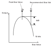 ⤢ zoomAn Output-versus-Bias-Value curve for setting record bias: the peak is marked Bp with a dashed leader to "Peak Bias Value", the recommended operating point is marked Br with a dashed leader to "Recommended Bias Value", a bracketed δdB gap spans the level at the peak and the level at Br, and the curve itself is labeled 10 kHz.
MKIV-2, MKIV-2E, BIII2, BIII-2E
| Tape Speed (ips) | 3.75 | 7.5 | 15 |
|---|---|---|---|
| Frequency (Hz) | 10 k | 10 k | 10 k |
| AGFA PEM 468 | 8.0 | 5.0 | 3.0 |
| AGFA PEM 469 | 8.0 | 5.5 | 3.5 |
| AMPEX 406/407 | 7.0 | 4.5 | 2.7 |
| AMPEX 456 | 8.0 | 5.5 | 3.0 |
| BASF LGR50P | 7.5 | 5.5 | 3.5 |
| BASF SM911 | 8.0 | 5.0 | 3.0 |
| SCOTCH 206/207 | 7.0 | 4.5 | 2.7 |
| SCOTCH 226/227 | 8.0 | 5.0 | 3.0 |
Unit: dB
BIII-F
| Tape Speed (ips) | 7.5 | 15 |
|---|---|---|
| Frequency (Hz) | 10 k | 10 k |
| AGFA 469 | 3.5 | 2 |
| AMPEX 456 | 3.5 | 2 |
| SCOTCH 2265.0 | 3.5 | 2 |
Unit: dB
7.4.2 Record Head Azimuth Adjustment↑ TOP
-
Thread the machine with a reel of blank tape.
-
Set both Record Ready buttons to the READY position and set both Monitor buttons to TAPE position.
-
Connect an external oscillator to the CH 1 and CH 2 INPUT connectors. Connect one probe of the oscilloscope to CH 1 and the other probe to the CH 2 OUTPUT connectors. Set the oscilloscope to display the input signals as a lissajous pattern.
-
Set the external oscillator to produce 1 kHz sine waves at +4 dBu or at the studio level.
-
Press the RECORD and PLAY buttons to enter Record mode.
-
Adjust the Record Head Azimuth adjustment screw A2 until the display on the oscilloscope becomes a straight line at 45 degrees as shown in Figure 7-5.
-
Set the external oscillator to 10 kHz, and adjust the Record Head Azimuth adjustment screw until the display on the oscilloscope becomes a straight line at 45 degrees as shown in Figure 7-5.
-
Set the external oscillator to 16 kHz, and adjust the Record Head Azimuth adjustment screw until the display on the oscilloscope becomes a straight line at 45 degrees as shown in Figure 7-5.
NOTE: Less and less adjustment is required as the frequency increases to cause the oscilloscope pattern to become correctly displayed. At higher frequencies, it will be impossible to achieve a perfectly straight line, some amount of jitter is normal. Adjust the azimuth screw until the best possible result is obtained.
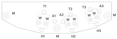 ⤢ zoomFigure 7-4 Head Assembly: the same head-mounting bracket view as Figure 7-2, with the T1/T2/T3, A1/A2/A3, W, H1/H2/H3 and M screws labeled identically.
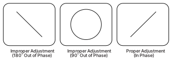 ⤢ zoomFigure 7-5 Waveshape on the Oscilloscope: the same three lissajous-pattern boxes as Figure 7-3 — 180° out of phase, 90° out of phase, and in phase — reprinted beside the Record Head Azimuth Adjustment steps.
7.4.3 Record Level Adjustment↑ TOP
- Thread the machine with tape and set the SPEED Select Switches for the Tape Speed most often used.
- Set both RECORD READY butons to the READY position.
- Set both Monitor button to TAPE position.
- Press the 1kHz Test Oscillator button on the AMP Panel. Adjust the Input Control knob so that the VU meters indicate 0VU. (Input a signal level of –10VU for 7.5 ips.)
- Press the PLAY and RECORD buttons to begin recording.
- Adjust VR305 on the REC/REP PCB Assembly so that the CH 1 VU meter indicates 0 VU (–10 VU if adjusting at 7.5 ips).
- Check to see that there is no difference in the indication on the VU meters when switching between SOURCE and TAPE modes.
- Repeat Steps 4 and 7 for Channel 2 by adjusting VR405.
7.4.4 Record Equalization Adjustment↑ TOP
NOTE: These adjustments should be performed after the Playback Equalization and Record Bias adjustments are completed.
- Thread the machine with tape and set the SPEED select switch to the HI position, (15 ips for High Speed, 7.5 ips for Low Speed).
- Press the 10kHz Oscillator Frequency button to activate the Test Oscillator.
- For High Speed models(HI; 15ips), adjust the Input Level knob until the VU meter indicates 0VU. For Low Speed models(HI; 7.5 ips), adjust the Input Level knob until the VU meter indicates –10VU.
- Set the Monitor button to TAPE position. Set both RECORD READY buttons to the Ready position, and press the PLAY and RECORD buttons to begin recording.
- Adjust VR303 (REC EQ H) on the REC REP PCB Assembly until the VU meter indicates 0 VU (–10 VU for Low Speed).
- Repeat Step 5 for Channel 2 using VR403.
- After setting the SPEED select switch to the Lo position, repeat Steps 3 through 6 using the REC EQ L trimmer (VR304 for CH1, VR404 for CH2). For High Speed models, adjust the trimmers until the VU meter indicates –10VU at step3 and 5. For Low Speed models, adjust the trimmers until VU meter indicates -20 VU at steps 3 and steps 5.
7.4.5 Low Frequency Reproduce Equalization Adjustment↑ TOP
- Thread a blank tape on the machine.
- Connect the external oscillator to the CH1 and CH2 input connectors.
- Set the Monitor button to SOURCE positon. Confirm that the VU meters indicate 0 VU.
- Press down the Monitor button to TAPE position. Set the machine to the speed which is most often used. Confirm that SW201 and 101 on the REC/REP AMP PCB has been set to the ON position.
- While Record the signal from the oscillator, adjust VR105 on the REC/REP AMP PCB Assembly so that the VU meter indicates 0 VU. Make the same adjustment for channel 2 using VR205.
7.4.6 Sel·Rep Level Adjustment↑ TOP
- Thread the machine with the tape of the type normally used for sessions.
- Press the 1kHz Oscillator button to activate the Test Oscillator.
- Adjust the Input Level Knob so that the VU meters indicate 0VU.
- After recording approximately 30 seconds of 1 kHz tone on the tape, rewind the tape to the starting point.
- Set the Monitor button to TAPE position. Press down the both SEL-REP buttons to place the machine into Sel-Rep Mode.
- Adjust VR101 (SEL-REP LEVEL) on the REC/REP AMP PCB Assembly so that the CH 1 VU meter indicates 0 VU.
- Repeat Step 6 for 2 channel using VR201.