MX-5050 MKIV-2 and BIII-2 Operation and Maintenance Manual — Digital Edition · Part 6 · PDF pages 66-77
Transport Adjustment and Parts Replacement
This section presents information and procedures for Transport Adjustment and Parts Replacement, and Adjustment after Replacement. Some parts require adjustment after replacement.
| 6.1 | Transport Access | 6-2 |
| 6.2 | Brake Torque Adjustment | 6-2 |
| 6.3 | Tape Lifter Adjustment | 6-4 |
| 6.4 | Capstan Motor Adjustment and Pitch Control Adjustment | 6-5 |
| 6.5 | Pinch Roller Pressure Adjustment | 6-6 |
| 6.6 | Tape Speed Adjustment | 6-8 |
| 6.7 | Reel Table Height Adjustment | 6-9 |
| 6.8 | Head Assembly Replacement | 6-10 |
| 6.9 | Head Position Adjustment | 6-11 |
6.1 Transport Access↑ TOP
The PCB Assemblies and main transport parts are located inside the machine. Therefore, to adjust these parts, certain panels must first be removed. Refer to § 2.4 for instructions on accessing these parts.
6.2 Brake Torque Adjustment↑ TOP
The brake adjustment is performed with the machine turned off.
The brake torque values are different for the supply side and take up side. Since the torque values for both sides are adjusted at one time, the adjusted torque is the best compromise for both sides.
Necessary Tools
Table 6-1
Necessary Tools
| 10.5" NAB Reel |
| String (2m) |
| Spring Scale (500g) |
- Turn off the power to the machine.
- Place an empty NAB reel (10") on the Supply Reel Table.
- Wind a piece of string a few turns counterclockwise on the hub of the NAB reel.
- Attach the spring scale to the end of the string.
- Hold the spring scale upright as shown in Figure 6-1.
- Pull on the scale slowly to make the reel rotate counterclockwise (direction B in Figure 6-1). While making sure that the cable does not rub against either flange, note the scale reading.
- Wind the string clockwise direction on the supply reel.
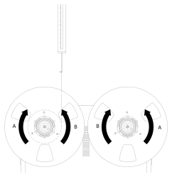 ⤢ zoomFigure 6-1 Brake Torque Measurement: two NAB reels shown side by side, each with a spring scale's string wound onto its hub and a curved arrow tracing the counterclockwise (B) and clockwise (A) directions, mirrored between the two reels.
- Repeat steps 4 ~ 6 for a clockwise reading on the supply side. The readings should fall within the range listed in the table below.
Table 6-2
Brake Tension Values
| MX-5050BIII | |
|---|---|
| A | 100 ~ 125g (3.6 ~ 4.5 ounces) |
| B | 225 ~ 275g (7.9 ~ 9.7 ounces) |
| MX-5050MKIV-2 | |
|---|---|
| A | 145 ~ 175g (5.1 ~ 6.2 ounces) |
| B | 315 ~ 385g (11.1 ~ 13.6 ounces) |
- If the readings are low in both directions, detach the brake spring from the anchor hole on the brake lever and attach the spring to the next hole located further away from the brake solenoid (refer to Figure 6-2).
- If the readings are high in both directions, move the spring anchor point closer to the brake solenoid.
- After the spring anchor point is moved, re-check the brake torque.
- Repeat the brake torque adjustment on the take-up reel.
NOTE: When measuring the brake torque of the take-up side, the torque of the clockwise rotation is larger than the counterclockwise torque.
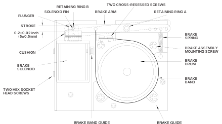 ⤢ zoomFigure 6-2 Brake Torque Adjustment: an exploded three-quarter view of the brake assembly — solenoid, plunger and retaining rings on the left, the brake drum and band mounted on the chassis at right, with the brake spring, its mounting screw, the band guide and brake guide all labeled, and the plunger stroke dimensioned at 0.2±0.02 inch (5±0.5mm).
6.3 Tape Lifter Adjustment↑ TOP
- Thread the machine with tape.
- Check the gap between tape and the lifters in Stop mode. If the gap is 1 ~ 2 mm, then the following adjustment is not necessary. If the gap is out of this range, then perform the following adjustment.
- Remove the reels on the transport panel. Referring to § 2.4, open the rear panel.
- Adjust the Lifter Stopper position by loosening the screws on the Lifter Stopper so that the appropriate gap is obtained. Refer to Figure 6-3.
- Close the rear panel.
- Confirm that the tape does not touch the head when in Fast Wind mode.
- If the tape touches the head, move the solenoid backward by loosening the screws holding the Lifter Solenoid Bracket. Refer to Figure 6-3.
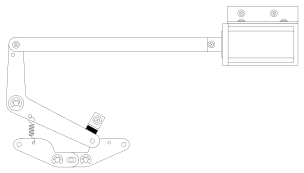 ⤢ zoomFigure 6-3 Tape Lifter Adjustment: a side view of the tape lifter arm and its solenoid, linked by a connecting rod, with the lifter stopper screw and spring shown at the arm's pivot.
6.4 Capstan Motor Adjustment and Pitch Control Adjustment↑ TOP
- Open the rear panel by removing the screws on the rear panel.
- Turn on the machine, and load the tape on the machine. Make sure that the Tape Speed mode is set to the FIX.
- Set the Speed Select button to 15 ips (HI on the High Speed version). If the machine is a Low Speed version, the speed adjustment is performed for 7.5 ips and 3.75 ips.
- Connect the oscilloscope between CP3 and CP2 (GND) on the Control PCB Assembly.
- Press the PLAY button. Adjust the oscilloscope so that the oscilloscope indicates one complete cycle of the square wave.
- While reproducing the tape, adjust VR1 (Gain) so that duty cycle of the square wave becomes 50%.
- While observing the oscilloscope, pinch the capstan shaft with the thumb and forefinger for several seconds. Be careful that the fingers are not caught between the Pinch Roller and Capstan Shaft. When pinching the Capstan Shaft, the waveform displayed on the oscilloscope becomes distorted. When the capstan shaft is released, the waveform returns to normal. Adjust VR4 (Damp) to minimize the time it takes the waveform to recover after releasing the capstan shaft.
- Change the tape speed to 7.5 ips (HI on Low Speed version or LO on High Speed version). Adjust the oscilloscope. Repeat step 6 with VR2 (Gain), and step 7 with VR5 (Damp).
- Change the tape speed to 3.75 ips (LO on Low Speed version). Adjust the oscilloscope. Repeat step 6 with VR3, and step 7 with VR6.
- Remove all measuring equipment. Close the rear panel.
- Clean the Capstan Shaft and Pinch Roller.
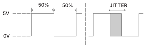 ⤢ zoomFigure 6-4 Waveform on Oscilloscope: two square-wave traces between 0V and 5V separated by a dashed vertical divider — the left trace with its two half-cycles each marked 50%, the right trace with its jitter window shaded and marked JITTER.
6.5 Pinch Roller Pressure Adjustment↑ TOP
The pinch roller pressure against the capstan shaft is determined by the pinch roller solenoid spring. The pinch roller solenoid spring is adjusted with a nut as shown in Figure 6-5.
The following adjustment should be performed after the machine has been operated in Play mode at least 30 minutes to obtain a steady solenoid force because the solenoid force decreases as temperature rises.
- MX-5050BIII
- Remove both reels from the reel tables.
- Tie a piece of string (15 cm) together to form a continuous loop. Place one end of the loop around the capstan pinch roller shaft.
- Press the EDIT button and then press the PLAY button. The pinch roller will move to make contact with the capstan shaft and both will rotate.
- Hook a spring scale (3kg) to the other end of the loop.
- Pull on the scale straight from the center of the capstan shaft as shown in Figure 6-5. Note the scale reading when the pinch roller loses contact with the capstan (the pinch roller stops rotating). The scale reading should be 2.5 ~ 2.7 kg (5.5 ~ 5.9 pounds).
- If a proper scale reading was not obtained in step 5, loosen the locknut and adjust the nut as shown in Figure 6-6. Turning the nut toward the spring increases pinch roller pressure. Tighten the locknut.
- After the adjustment has been completed, check that the plunger of the solenoid reaches the bottom of the the solenoid coil (pinch roller can easily be pushed away from the capstan shaft). If the plunger of the solenoid does not reach the bottom, loosen the locknut and turn the pressure nut away from the spring until the plunger just reaches the bottom. Check the pressure adjustment again and tighten the locknut.
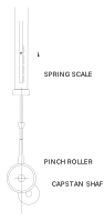 ⤢ zoomFigure 6-5 Pinch Roller Pressure Measurement: a spring scale hooked to a string loop around the capstan pinch roller shaft, hung vertically above the pinch roller and capstan shaft.
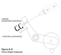 ⤢ zoomFigure 6-6 Pinch Roller Solenoid: the pinch roller solenoid's spring-loaded pressure nut and lever arm, with curved arrows marking the loosen (counterclockwise) and tighten (clockwise) directions.
MX-5050MKIV-2
-
Remove the pinch roller cap screw and the roller cap.
-
Thread a hex socket head screw (M3, length 25~30mm) into the pinch roller.
-
Press the EDIT button and then press the PLAY button. The pinch roller will move to make contact with the capstan and both will rotate.
-
Measure the pinch roller pressure by using the Push function (piston part, not hook part) of the spring scale.
Put the end of the piston part of the spring scale (3kg) on the hex socket head screw (M3) from the direction of the capstan shaft. Refer to Figure 6-7. Be careful that the piston part does not touch the capstan shaft.
-
Push on the scale and note the scale reading when the pinch roller just loses contact with the capstan shaft (the pinch roller stops rotating).
The scale reading should be 2.7 ~ 2.8 kg (5.9 ~ 6.2 pounds).
-
If a proper scale reading is not obtained in step 5, adjust the nut shown in Figure 6-6. Loosen the LOCK nut and Adjust the Adjustment Nut . Turning the Nut in the spring direction increases the pinch roller pressure. Tighten the Lock Nut after adjustment.
-
Confirm that the plunger reaches the bottom when the solenoid is activated. If not, the solenoid pressure will not be strong enough so that even a slight pressure will be able to move the pinch roller away from the capstan shaft.
-
If the plunger does not reach the bottom of the solenoid, loosen the Double nut and readjust the pressure.
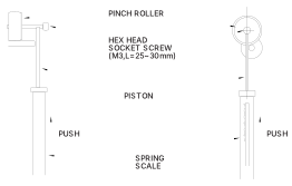 ⤢ zoomFigure 6-7 Pinch Roller Pressure Measurement: the same spring-scale-and-piston measurement shown in two views — a side view of the pinch roller at left, an end view with the capstan shaft behind it at right — the piston in each view pushing on the M3 hex socket head screw threaded into the pinch roller, with PUSH arrows and the spring scale labeled in both.
6.6 Tape Speed Adjustment↑ TOP
Tape speed is adjusted by measuring the tape speed using a special test tape, and then adjusting the speed to bring it into the desired range. Tape speed should be adjusted at the normally used tape speed. Also, since tape tension affects tape speed, to accurately measure tap speed, the test tape should first be played normally from the supply side, and then the reels should be reversed and the tape played near the end. In this way, the average tape speed from one end of the tape to the other can be determined.
Note: A special tape is required for this procedure. If an accurate speed tape is not available, please contact your Otari dealer for further information.
Follow the procedure below to measure and adjust the tape speed.
- Clean the Head, Capstan Shaft and Pinch Roller before the measurement.
- Press the Speed Mode Select button to set the FIX mode. Set the Record mode button to SAFE position (protruded position).
- Connect the frequency counter to the output connector. Press down the Monitor button set TAPE position.
- Set the machine to the most often used tape speed.
- Wind the Test Tape of the selected speed around a blank of a NAB (10.5") reel. Set this Test Tape on the supply side. Thread the tape on the machine. Set the Reel Size Select switch to "L" size.
- Press Play and read the frequency counter indication. This reading should be 2994Hz to 3006Hz (3000Hz ± 0.2 %) with a 3000Hz speed test tape. Reverse the reels on the machine and check the speed again at the other end of the tape to determine the average overall tape speed.
- If the reading is out of range, adjust DIP SWs 1-4 and 1-5 on the CONTROL PCB Assembly for the best speed reading. The switches affect tape speed as shown in the table below.
Table 6-3
Tape Speed Settings
| SW1-4 | 1-5 | OFFSET |
|---|---|---|
| ON | ON | +0.1% |
| OFF | ON | -0.1% |
| ON | OFF | -0.2% |
| OFF | OFF | 0% |
6.7 Reel Table Height Adjustment↑ TOP
The Reel Table may be detached from the machine by removing the three cross-recessed screws accessible from the side of the transport.
- Remove the side panel by removing the screws on the panel.
- Loosen the height adjustment screws (hex socket head screws holding the Reel Table shaft) and adjust the height of the table. While holding the table at the appropriate height, tighten the adjustment screws.
- Set the Reel onto the Reel Table. Make sure that the Reel Flange does not touch the transport panel.
- Mount the side panels to the machine.
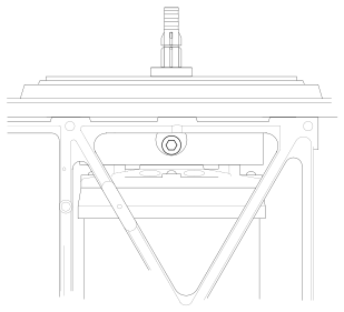 ⤢ zoomFigure 6-8 Reel Table Height Adjustment: a cutaway side view of the Reel Table assembly, its center shaft threaded up through the table top, with the height adjustment screws visible in the mounting bracket below.
6.8 Head Assembly Replacement↑ TOP
The Head Assembly is mounted on the tape guide posts and is attached to the Guide Posts with screws marked "M" (refer to Figure 6-9). Each Head Stack is attached to the Head Bracket with screws marked "W", and the Head Brackets are attached to the Head Base with the screws marked "H" "A" and "T". These screws are used to adjust the position of the head.
When one of the head stacks needs to be replaced, use the following procedure.
- Raise the Head Cover
- Remove the screws marked "M" and remove the head base from the tape guides.
- Unsolder the lead wires coming from the Head PCB.
- Remove the Head Stack from the Head Base by removing screws "A", "T" and "H".
- Attach the new Head Stack to the Head Base with the screw removed in Step 4.
- Resolder the wires removed in Step 3.
- Mount the Head Base to the Tape Guides with the screws "M".
After replacement of the heads, perform Head Position adjustment § 6.9) and Azimuth Adjustment (§ 7.3.1 and § 7.4.3)
In addition to the above adjustments, the following adjustments are necessary.
Repro Head
B. Reproduce EQ Adjustment § 7.3.3
Record Head
A. Record Bias Adjustment § 7.4.1
B. Record Level Adjustment § 7.4.3
C. Record EQ Adjustment § 7.4.4
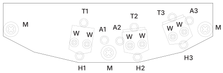 ⤢ zoomFigure 6-9 Head Assembly: the head base bracket seen from the front, with three head stacks each shown mounted by their W screws and the A and T position-adjustment screws, the H height/zenith screws along the bottom edge, and three M guide-post mounting screws — one at each end and a third at bottom center.
6.9 Head Position Adjustment↑ TOP
Whenever replacing a head, the following head position adjustments are necessary. If the tape does not contact the heads properly, perform the following adjustments.
NOTE: If the tape does not contact the heads properly due to improper alignment, any one of the following problems may occur.
Reproduce Head Wrong Position
High Frequency Level Decreasing
Level Fluctuation
Record Head Wrong Position
High Frequency Level Decreasing
Level Fluctuation
Erase Head Wrong Position
Deterioration of the Erase Ability
- Height /Zenith Adjustment
Perform the following adjustment after raising the head cover.
- Thread the machine with a tape that can be disposed of after use.
- Adjust the head height and zenith visually by turning the screws marked "T" and "H" in Figure 6-9 to move the tape to the middle of the head.
- After the adjustment, mark the head surface with Head Marker Ink or a Marker Pen.
- Play the tape for about ten seconds.
- Inspect the face of each head where the passage of the tape has worn away the ink. If the wear pattern does not match that shown in Figure 6-10, readjust the screws " T" and " H ".
- After reapplying the ink, play the tape as in step 4, and again inpsect the face of each head. Repeat this process until the wear pattern is correct.
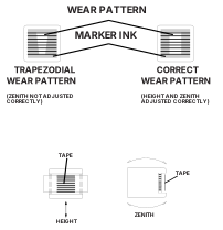 ⤢ zoomFigure 6-10 Height/Zenith Adjustment: a wear-pattern comparison of two head faces — a trapezoidal wear pattern (zenith not adjusted correctly) beside a correct, even wear pattern (height and zenith adjusted correctly), both traced against the head's marker ink; below, two small cross-section views of the tape wrapped against the head showing the height and zenith directions.
- Wrap Adjustment
- While reproducing 8kHz portion of the Low Speed Test Tape, apply pressure with a cotton swab to the left side of the head. Observe the level change. If the level increases by more than 0.5 dB, wrap adjustment is necessary. In the same way, if the level increases by 0.5 dB when applying pressure from the right side, wrap adjustment is necessary.
- Turning the screw marked "W" in Figure 6-9, visually adjust the head so that the tape approaches and leaves the head gap at approximately the same angle. If the level increases by more than 0.5dB when pressing on the tape on the right side of the head, rotate the head clockwise. If the level increases by more than 0.5dB when pressing the tape on the left side of the head, rotate the head counterclockwise.
- Repeat step 1 and confirm that the level increases by less than 0.5 dB.
NOTE: Refer to the § 7.3.2 and § 7.4.4 for azimuth adjustment procedures.
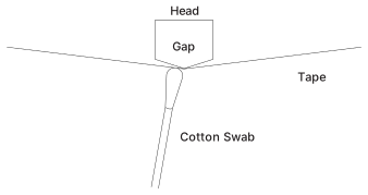 ⤢ zoomFigure 6-11 Wrap Adjustment: the tape approaching and leaving the head gap at the same angle, with a cotton swab pressing against the tape's left side to test the wrap.