MX-5050 MKIV-2 and BIII-2 Operation and Maintenance Manual — Digital Edition · Part 5 · PDF pages 62-65
Maintenance
The maintenance procedures described in this section should be performed at regular intervals. Cleaning and demagnetizing the heads and tape path should be performed before each recording session, and must be performed before any electronic alignments are performed. Lubrication should be performed after 1000 hours of operation or after 6 months, whichever comes first.
This section includes the following sub sections.
| 5.1 | Maintenance Scheduling | 5-2 |
| 5.2 | Demagnetizing | 5-2 |
| 5.3 | Cleaning the Tape Path | 5-3 |
| 5.4 | Lubrication | 5-4 |
5.1 Maintenance Scheduling↑ TOP
Routine maintenance is necessary to keep the MX-5050 in peak operating condition. The following is a chart for a suggested maintenance schedule.
Table 5-1
Maintenance Time Table
| Adjustment Item | Before Each Session | Every 3 to 6 months | Section |
|---|---|---|---|
| Demagnetizing | ✓ | § 5.2 | |
| Cleaning | ✓ | § 5.3 | |
| Lubrication | ✓ | § 5.4 | |
| Pinch Roller Pressure | ✓ | § 6.5 | |
| Equalizer (REP, REC)Setting | ✓ | § 7.3.3, § 7.4.4 | |
| REP, REC Level | ✓ | § 7.3.2, § 7.4.3 | |
| Bias Adjustment | ✓ | § 7.4.1 |
Table 5-2
Tools Required for Maintenance
| Tool Names | Parts No. | Used for |
|---|---|---|
| OTARI Cleaningn Kit | ZA-51B | Cleaning the Head |
| Isopropyl Alcohol | Included in ZA-51B | Cleaning the Tape Guide, Capstan Pinch Roller, Capstan Shaft |
| Head Eraser | Any | Demagnetizing the Head, Guide |
| Lubrication Oil | PZ9E003 | Lubirication for Capstan Motor |
5.2 Demagnetizing↑ TOP
Demagnetizing (sometimes called degaussing, although that term is more often applied to bulk tape erasure) is a necessary procedure and should be performed before every recording session and prior to performing any alignments. Demagnetizing should always be done with extreme caution.
DEMAGNETIZING CAUTION: To avoid damaging the MX-5050, always make sure the POWER switch is off before proceeding. The AC field created by the demagnetizer is extremely powerful and could seriously damage the electronics if they are on. Make sure that all recording tapes, especially alignment tapes, are removed from the vicinity of the MX-5050.
Never turn the power to the demagnetizer on or off unless it is at least 1 meter (3 feet) away from the MX-5050. When the demagnetizer is turned on or off, an extremely strong moving magnetic field is created which could possibly place a permanent magnetic charge on parts of the machine. The demagnetizer would not be powerful enough to remove these charges under normal circumstances, and the parts might have to be removed and discarded. Use only a demagnetizer with high flux density; inexpensive "Hi-Fi" type demagnetizers can leave residual fields that will cause more harm than benefit.
-
Turn off the MX-5050 POWER switch.
-
With the demagnetizer at least 1 meter (3 feet) from the MX-5050, plug the demagnetizer into the AC mains and turn it on.
-
Slowly move the demagnetizer toward the Supply Tension Arm until the tip is approximately 3 mm (1/8") away from the arm.
-
Slowly move the tip of the demagnetizer up and down along the arm so that the entire surface is exposed to the demagnetizing field. Do not touch any part of the MX-5050 with the demagnetizer.
-
Slowly move the demagnetizer at least 1 meter (3 feet) away from the MX-5050.
-
Working from left to right repeat Steps 3, 4, and 5 for each of the following metal parts in the tape path:
A. Supply Tension Arm
B. Supply Tape Guide
C. Supply Tape Lifter
D. Erase Head
E. Center Tape Guide
F. Record Head
G. Take-up Tape Lifter
H. Reproduce Head
I. Take-up Tape Guide
J. Capstan Shaft
K. Take-up Tension Arm -
When all the above parts have been demagnetized, slowly move the demagnetizer at least 1 meter (3 feet) away from the MX-5050 and turn it off or unplug it.
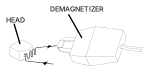 ⤢ zoomFigure 5-1 Demagnetizing the Head: an isometric line drawing of the demagnetizer's tip held close to the tape head, with an arrow tracing the sweeping motion along the head's face; both parts labeled.
5.3 Cleaning the Tape Path↑ TOP
It is extremely important to clean the entire tape path regularly. Oxide and dirt will be shed from the tape and accumulate on these parts, causing a build-up that can degrade audio performance, cause slippage and undue wear on the tape.
CAUTION: Never use any metallic item or abrasive to clean the heads or any other tape guidance parts. Never use spirits, lacquer thinner, acetone or other solvents on the tape heads. Rubbing alcohol should be avoided since it contains oil that will leave a residue. The entire tape path should be cleaned and demagnetized before performing any adjustments.
-
Turn off the machine.
-
Lift up the head cover.
-
Moisten a cotton swab in pure isopropyl alcohol, and wipe the entire surface of the Supply Tension Arm. Allow the Tension Arm to dry by evaporation.
-
Moisten additional swabs and clean the following parts:
A. Supply Tension Arm
B. Tacho Roller
C. Supply Tape Guide
D. Supply Tape Lifter
E. Erase Head
F. Center Tape Guide
G. Record Head
H. Take-up Tape Lifter
I. Reproduce Head
J. Take-up Tape Guide
K. Capstan Shaft
L. Pinch Roller
M. Take-up Tension Arm
CAUTION: Do not use alcohol moistened swabs to clean the Pinch Roller. To avoid embedding dust and lint particles in the surface of these rollers, use only an alcohol moistened Lint-Free cloth to gently clean the rollers.
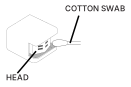 ⤢ zoomFigure 5-2 Cleaning the Head: an isometric line drawing of the tape head with a cotton swab held against its face; both parts labeled.
5.4 Lubrication↑ TOP
The Capstan Motor in MX-5050 machines utilizes an Oilite bearing at the front end, which requires lubrication.
Use only Otari oil P/N PZ9E003.
To lubricate the Capstan Motor bearing, follow these steps:
- Remove the pinch roller cap by removing the screw on it.
- Remove the pinch roller from the pinch roller shaft.
- Remove two hex socket head screws on the head housing cover.
- Remove the Tape Guide at the take up side. Remove the two screws holding the Rear Head Escutcheon.
- Remove the dust cap on the Capstan Motor with a pair of tweezers. Refer to Figure 5-3.
- Apply 2 or 3 drops of oil to this felt collar. Do not over lubricate.
- Wipe off any excess oil and install the dust cap, Rear Head Escutcheon, head housing cover, pinch roller and pinch roller cap in that order.
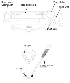 ⤢ zoomFigure 5-3 Lubrication: two line drawings — the head-block assembly with the Rear Head Escutcheon, Head Housing, Pinch Roller, Tape Guide and Dust Cap labeled, and an exploded view of the Capstan Motor's dust cap and felt pad with a bottle of Lubrication Oil PZ9E003 above it, all labeled.