MX-5050 MKIV-2 and BIII-2 Operation and Maintenance Manual — Digital Edition · Part 4 · PDF pages 48-60
Operation
This section contains, first, a list and accompanying brief explanation of each of the operating conditions (or modes) of the MX-5050, and second, a detailed explanation of each operation or activity associated with the operation of the MX-5050 Tape Recorder. Please read both parts of this Section when first becoming familiar with the machine, and then refer to them whenever more information about the operation of the machine is required.
This section includes the following sub sections.
| 4.1 | Operation Mode Reference Tables | 4-2 |
| 4.2 | Modes of Operation | 4-3 |
| 4.2.1 | Transport Modes | 4-3 |
| 4.2.2 | Audio Channel Modes | 4-4 |
| 4.3 | Operating the MX-5050 | 4-5 |
| 4.3.1 | Placing Reels on the Machine | 4-5 |
| 4.3.2 | Threading the Tape | 4-6 |
| 4.4 | Operation of the Transport | 4-7 |
| 4.4.1 | Playing Back the Tracks | 4-7 |
| 4.4.2 | Recording the Tracks | 4-7 |
| 4.4.3 | Sel-Rep Recording | 4-8 |
| 4.4.4 | Fast Wind and CUE monitor | 4-8 |
| 4.4.5 | Tape Editing | 4-9 |
| 4.4.6 | Using the Pitch Control Feature | 4-10 |
| 4.5 | Locator Operation | 4-11 |
| 4.5.1 | Storing Tape Locations | 4-11 |
| 4.5.2 | Search Mode | 4-11 |
| 4.5.3 | Search Play Mode | 4-12 |
| 4.5.4 | Search Zero Mode | 4-12 |
| 4.5.5 | Search Start Mode | 4-12 |
| 4.5.6 | Repeat Mode | 4-13 |
| 4.6 | Test Oscillator | 4-13 |
4.1 Operation Mode Reference Tables↑ TOP
Table 4-1
Transport Modes
| MODE | CONTROL | EXPLANATION |
|---|---|---|
| Stop | STOP | Tape motion stops. |
| Play | PLAY | Tape moves from Supply to Take-up at the currently selected speed. |
| F.Fwd | F.FWD | Tape moves from Supply to Take-up at Fast Wind speed. |
| Rewind | REWIND | Tape moves from Take-up to Supply at Fast Wind speed. |
| Record * | RECORD or RECORD + PLAY | Any channel in Record Ready begins to record. |
| Rehearse | REHEARSE | The track in Ready mode changes to INPUT monitor when the Punch In is performed. |
| Edit Ready | EDIT in Stop mode | Transport is ready for Edit or Edit Play mode. |
| Edit Play | PLAY in Edit Ready mode | Tape moves towards Take-up reel but Take-up reel does not turn (Dump Edit). |
| Cue | CUE in Rewind or F.Fwd mode | Lifters will be retracted to allow audio to be monitored. |
| Vari Speed | Speed Mode switch to Vari | Tape speed is controlled by the Pitch Control. |
* Selected with SW 1-2 on Transport Control PCB.
Table 4-2
Audio Channel Modes
| MODE | CONTROL | EXPLANATION |
|---|---|---|
| Ready | READY/SAFE switch to READY | The selected channel will enter Record when the RECORD and PLAY buttons are pressed. |
| Safe | READY/SAFE switch to SAFE | The selected channel will not enter Record. |
| Input Monitor | Monitor Select switch to INPUT | The signal at the OUTPUT connector for that channel is present the signal at the INPUT connector. |
| Sel·Rep Monitor | Monitor Select switch to SEL·REP | The signal at the OUTPUT connector is the signal on tape reproduced by the Record Head. |
| Repro Monitor | Monitor Select switch to REPRO | The signal at the OUTPUT connector is the signal on tape reproduced by the Reproduce Head. |
Table 4-3
Auto Locator Modes
| MODE | CONTROL | EXPLANATION |
|---|---|---|
| Set mode | SET button | Tape locations can be entered for Cue Points using the ZERO, 1, 2, 3, REPEAT mode and CLR buttons. |
| Repeat mode | REPEAT + two SEARCH buttons | Tape plays from 1st to 2nd Cue Points, then rewinds to 1st and repeats. |
| Search | SEARCH 1/2/3 | Tape is moved to the Cue Point at Fast Wind speed and stops. |
| Search Zero | SEARCH ZERO | Tape is moved to 0:00:00 at Fast Wind speed and Stops. |
| Search Play | PLAY + SEARCH 1/2/3 | Tape is moved to the Cue Point at Fast Wind speed where it enters Play. |
4.2 Modes of Operation↑ TOP
4.2.1 Transport Modes↑ TOP
-
Play mode: In Play mode, the tape moves from Supply reel to Take-up reel at the currently selected tape speed. To enter Play mode, press the PLAY button. The Lamp on the PLAY button will become illuminated. Play mode can be entered from any mode except Edit Ready and Search modes.
-
Fast Forward mode: In Fast Forward mode, the tape moves from the Supply reel to the Take-up reel at Fast Wind speed. To enter Fast Forward mode, press the F.FWD button. The Lamp on the F.FWD button will become illuminated. Fast Forward mode can be entered from Stop, Play, Rewind and Record modes.
-
Rewind mode: In Rewind mode, the tape moves from the Take-up reel to the Supply reel at Fast Wind speed. To enter Rewind mode, press the REWIND button. The Lamp on the REWIND button will become illuminated. Rewind mode can be entered from Stop, Play, Fast Forward and Record modes.
-
Record mode: To enter Record mode, press the RECORD and PLAY buttons when a channel is in Record Ready mode, or if it is selected to do so, press the RECORD button while the machine is in Play mode. The Lamp on the RECORD button will steadily illuminate when the MX-5050 is in Record mode.
-
Edit Ready mode: To enter Edit Ready mode, press the EDIT button while in Stop mode. The Lamp on the EDIT button will flash when the MX-5050 is in Edit Ready mode. Edit Ready mode can be entered even if there is slack in the tape path.
-
Edit Play mode: To enter Edit Play mode, press the PLAY button while in Edit Ready mode. The pinch roller will engage the capstan, the Take-up reel will not rotate, and the tape will be spilled from the right side of the transport. To enter Edit Play mode while in Play mode, press the EDIT button. The Take-up reel will stop rotating and the tape will be spilled from the right side of the transport.
-
Cue mode (Lifter Defeat): In Cue (or Lifter Defeat) mode, the tape lifters will be retracted and the audio attenuated allowing the signals on the tape to be monitored while tape is moving at Fast Wind speed. To enter Cue mode, press the Cue button while in Fast Forward or Rewind mode. There are two ways to enter the CUE mode as follows.
Tapping the CUE button causes the Tape Lifter to remain retracted until the CUE button is pressed again. This monitoring is convenient when monitoring the tape for a long time.
Holding the CUE button pressed causes the tape lifter to remain retracted as long as the button is held pressed.
4.2.2 Audio Channel Modes↑ TOP
-
Record Ready mode: When the RECORD and PLAY buttons are pressed, any channel which is in Record Ready will begin to Record. To place a channel into Record Ready mode, press the RECORD mode button for that channel. The Record mode indicator will illuminate and the indicator on the RECORD button will flash.
-
Record Safe mode: In Record Safe mode, Record mode cannot be entered. To place a channel in Record Ready mode into Record Safe mode, press the RECORD mode button for that channel to the SAFE postion (not depressed). The Record mode indicator(s) will extinguish. When the Record mode indicator is extinguished, that channel is in Record Safe mode.
-
Input Monitor mode: In Input Monitor mode, the signal at the OUTPUT connectors, VU Meters, PHONES connector, and Monitor Speaker is the signal present at the INPUT connector for that channel. To place a channel into Input Monitor mode, set the Monitor button for that channel to SOURCE position (not depressed).
-
Sel-Rep Monitor mode: In Sel·Rep (Selective Reproduce) Monitor mode, the signal at the OUTPUT connectors, VU Meters, PHONES connector, and Monitor Speaker is the signal on tape reproduced by the Record Head for that channel. To place a channel into Sel·Rep Monitor mode, press the SEL·REP Monitor button for that channel.
4.3 Operating the MX-5050↑ TOP
4.3.1 Placing Reels on the Machine↑ TOP
- Using 5" or 7" EIA Reels
- Turn the Reel Clamp portion of the Reel Spindle until it lines up with the three Reel Drive Pins on the Reel Table.
- Place the reel on the Reel Table so that the Reel Drive Pins are inserted into the slots in the reel.
- Lift and turn the Reel Clamp portion of the Reel Spindle 60 degrees (until it clamps the reel in place).
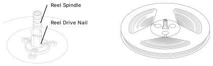 ⤢ zoomTwo line drawings for mounting 5-inch or 7-inch EIA reels: a cutaway of the Reel Spindle and Reel Drive Nail on the Reel Table, and the assembled reel seated on the three reel drive pins.
- Using 10.5" NAB Hub Reels
- Turn the Reel Clamp portion of the Reel Spindle until it lines up with the three Reel Drive Pins on the Reel Table.
- Place the Reel Adapter on the Reel Table and lift and turn the Reel Clamp portion of the Reel Spindle 60 degrees (until it clamps the Adapter in place.)
- Place the Reel on the Reel Adapter and lift and turn the upper portion of the Adapter until it locks the reel in place.
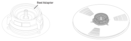 ⤢ zoomTwo line drawings for mounting 10.5-inch NAB hub reels: the Reel Adapter shown alone, and the Reel Adapter with a reel locked onto it on the Reel Table.
- Using AEG (or DIN) Hubs (Optional)
- Turn the Reel Clamp portion of the Reel Spindle until it lines up with the three Reel Drive Pins on the Reel Table.
- Place the Reel Adapter on the Reel Table and lift and turn the Reel Clamp portion of the Reel Spindle 60 degrees (until it clamps the Adapter in place).
- Place the hub of tape on the Adapter and rotate the Adapter 90 degrees to lock the hub in place.
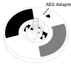 ⤢ zoomA line drawing of the AEG Adapter mounted on the Reel Table, its shaded rotating collar shown partway through locking a tape hub in place.
4.3.2 Threading the Tape↑ TOP
-
Mount an empty reel on the Take-up side and mount a reel of tape on the Supply side.
NOTE: Select the reel diameter by pressing the REEL SIZE T.UP S/L and REEL SIZE SUP S/L buttons after mounting the reels.
-
Thread the tape from the Supply reel to the Take-up reel as shown in Figure 4-1 and turn the Take-up reel clockwise to remove any slack from the tape path.
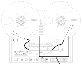 ⤢ zoomFigure 4-1 Tape Threading: a top-down view of the tape transport deck with the supply and take-up reels mounted above the transport control panel (POWER, SPEED MODE, PITCH CONTROL, REEL SIZE, SET/SEARCH/REPEAT/CLR and CUE/EDIT controls labeled), a bold line tracing the tape path from the supply reel across the head block to the take-up reel, and a rectangle around the head-block area with an arrow leading down to an enlarged detail view.
Note: When threading a tape onto the machine, be sure that the tape is threaded correctly (see the enlarged figure to the right).
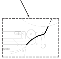 ⤢ zoomEnlarged detail of the tape path through the head block: the bold tape line threading past the head assembly, a capstan and a pivoting tension arm, framed in a dashed box, matching the rectangle highlighted in Figure 4-1.
4.4 Operation of the Transport↑ TOP
4.4.1 Playing Back the Tracks↑ TOP
- Set both Record mode buttons to the SAFE position (not depressed).
- Press the Monitor button to the TAPE position.
- Press the PLAY button to start Play mode.
- Press the STOP button to stop Play mode.
4.4.2 Recording the Tracks↑ TOP
- Press the RECORD mode button for the channels to be set to the READY position.
- Set the MONITOR buttons of the channels to be recorded to the SOURCE position (not depressed).
- Adjust the Input Level Control of each channel so that the VU meter indicates 0 VU at the reference input level. (With this level setting, the peak indicator will illuminate occasionally.)
- Press the CLR and T-IPS-% keys to clear the Tape Timer display.
- Press the PLAY and RECORD buttons together to place the transport into Record mode. The RECORD and PLAY buttons on the transport illuminate.
- In RECORD mode, the recorded signal can be monitored by pressing the MONITOR button to the TAPE position.
NOTE: When a channel is set to SEL REP mode, the channel can not enter RECORD mode. Confirm that the SEL REP button of the recording channel is not pressed.
NOTE: While the machine is in PLAY mode, pressing the RECORD button places the machine in Record mode. This operation is called Punch In. Punch In operation is selected from the following methods with SW1-2 on the REC/REP AMP PCB Assembly.
-
Pressing the RECORD button in PLAY mode enters Record mode.
-
Pressing the RECORD and PLAY buttons together while in Play mode enters the Record mode.
NOTE: Pressing the PLAY button while the machine is still in Record mode exits the Record mode and enters the Play mode without stopping the machine. This operation is called Punch Out. Punch Out operation is selected from the following methods with SW1-3 on the REC/REP AMP PCB Assembly.
-
Pressing the PLAY button while in RECORD mode exits the Record mode and enters the Play mode.
-
Pressing the STOP button while pressing the RECORD button exits Record mode and enters Play mode.
4.4.3 SEL-REP Recording↑ TOP
SEL-REP operation means that the tape is reproduced with the Record Head instead of being reproduced with the Reproduce Head. With this operation, the signal reproduced with the Record head is recorded to the other track without time delay. The following is the procedure of the SEL-REP operation.
-
Rewind the tape to the starting point of the SEL-REP operation.
-
Press the RECORD READY button of the recording channel to place it in the READY position.
-
Set the MONITOR button of the channel to to be recorded to the SOURCE position (not depressed). Set the Monitor button of the channel to be monitored to TAPE.
-
Adjust the Input Level knob of each channel so that the VU meter indicates 0VU. (With this level setting, the peak indicator sometimes illuminates.)
-
Press the SEL-REP mode button of the channel being monitored to the SEL-REP position.
-
Press the PLAY button to begin playback.
When the RECORD button is pressed at the overdubbing point, the channel set to READY is changed to INPUT mode and recording begins.
-
Press the STOP button to stop recording.
When ready to Punch Out, press the PLAY button at the end of the recording.
4.4.4 Fast Wind and Cue Monitor↑ TOP
Pressing the F.FWD button places the machine into fast wind mode. Pressing the RWD button places the machine in rewind mode. The machine can enter these modes from any mode other than EDIT mode. When the machine is in F.FWD or RWD mode, the tape is normally lifted away from the heads. To monitor the signal on the tape while fast winding press the CUE button. When the CUE button is pressed the lifters are retracted and the tape comes into contact with the heads. There are two methods of operating the CUE button as described below.
-
Tapping the CUE button
Tapping the CUE button momentarily retracts the lifters and allows the tape to make contact with the heads so that the tape can be monitored. Tapping the CUE button again raises the lifters.
-
Holding the CUE button down
Holding the CUE button down retracts the lifters for as long as the button is held down.
4.4.5 Tape Editing↑ TOP
- Move the tape at the beginning of the edit section. When the tape reaches to the editing point, rotate the reel by hand to accurately locate the editing point, and finally place the editing point to the reproduce head.
- Press the EDIT button to enter the EDIT Ready mode. The EDIT button blinks to show that the machine is in Edit Ready mode.
- Mark the point at the REPRO Head with a marker pen.
- Draw out the tape from the Head Assembly. Place the tape on the Splicing Block. Cut the tape along with the slot on the Splicing Block.
- While holding the unnecessary part of the tape, thread the tape between the Pinch Roller and Capstan Shaft.
- Press the PLAY button and the tape will spill off from the right end of the transport to the floor. The EDIT and PLAY buttons illuminate to tell the machine is in EDIT mode.
- When the tape reaches to the end of the edit section, press the STOP button to stop the machine. Repeat step 3 and 4 and splice the tape until the desirable edited tape is obtained.
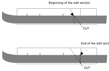 ⤢ zoomFigure 4-2 Editing a Tape: two stacked diagrams of the tape path over the head block, the upper one marking the beginning of the edit section with a CUT line and leader, and the lower one marking the end of the edit section with its own CUT line and leader.
4.4.6 Using the Pitch Control Feature↑ TOP
The speed of the tape can be changed over a range of ± 20%as it is being recorded or played. This feature makes it possible to compress or extend material to fit it into a time slot, or to change the pitch for special effects, etc. To manually adjust the speed of the MX-5050.
- Press the SPEED MODE select button until the VARI mode indicator illuminates.
- Use the Pitch Control knob to vary the capstan speed as desired. Turning the knob counterclockwise decreases the speed, turning it clockwise increases the speed. The pitch can be changed in 0.01% increments.
The MX-5050 allows the last Vari Speed setting to be stored in memory for recall the next time the Vari Speed feature is used.
- Presetting the Vari Pitch Value in FIX Speed mode
- Change the Tape Time Display to Speed Change indication (%) by pressing the TIME IPS % button.
- Press the SET button and display the desired vari pitch value on the display by pressing the SEARCH and CLEAR keys. The display changes as follows.
Table 4-4
Vari Pitch Preset
| Key | Changing Item | Change |
|---|---|---|
| REPEAT | +/- | -/no display |
| SEARCH ZERO | 10% column | no display 1 2 |
| SEARCH 1 | 1% column | 0-9 |
| SEARCH 2 | 0.1% column | 0-9 |
| SEARCH 3 | 0.01% column | 0-9 |
- Set the Speed Mode Switch to the VARI Position. The machine starts reproducing at the set vari speed.
- Recalling the Previous Vari Pitch Speed Setting
- Change the Tape Time Display to Speed Change indication (%) by pressing the TIME IPS % button.
- Display the previous vari pitch speed setting by pressing the SET button.
- If no change is required, set the Speed Mode Switch to the Vari position. The capstan motor starts rotating at the vari pitch speed setting.
4.5 Locator Operation↑ TOP
The MX-5050 Series tape recorders feature a built-in Auto Locator which has three cue point memories, a zero location memory, and the ability to repeat play between any two selected tape locations.
4.5.1 Storing Tape Locations↑ TOP
There are two ways to store tape locations into the locator memory: The tape locations can be captured "on the fly", or can be entered in SET mode.
-
Capturing Tape Locations
Pressing an unilluminated SEARCH key while reproducing the tape causes that tape location to be stored in the cue point memory of that SEARCH key. The LED of the key illuminates to indicate that a CUE point has been stored.
To clear the CUE point, press the CLR button and the corresponding SEARCH key.
-
Cue Point Set Mode
In SET mode, the desired tape location can be displayed on the display by using the SEARCH ZERO, SEARCH 1/2/3, REPEAT and CLR keys, and can be stored in the SEARCH CUE points.
- To enter the machine into the SET mode, press the SET key. The indicator on the SET key illuminates and the decimal points on the display start to blink.
- After placing the machine into the SET mode, enter the desired tape time with the following keys.
Table 4-5
Cue Point Set Mode
| KEY | CHANGING ITEM | CHANGE |
|---|---|---|
| SEARCH ZERO: | 10 Hour | 0,1,2,- |
| SEARCH1: | 1 Hour | 0-9 |
| SEARCH2: | 10 Minute | 0-5 |
| SEARCH3: | 1 Minute | 0-9 |
| REPEAT: | 10 Seconds | 0-5 |
| CLR: | 1 Second | 0-9 |
- After the desired tape time is indicated on the display, press the SEARCH key while pressing the SET key to store the tape location on the display as a CUE point.
- To exit from the SET mode, press the CLR key while pressing the SET key.
4.5.2 Search Mode↑ TOP
To enter Search mode, press any illuminated SEARCH 1/2/3 button. In this mode, the machine will move the tape at Fast Wind speed to the Cue Point and stop. During Search mode, the tape location will be shown on the display briefly, and the button indicator will flash.
4.5.3 Search Play Mode↑ TOP
To enter Search Play mode, press the PLAY button while in Search mode. The Lamp on the PLAY button will flash, and the MX-5050 will enter Play mode when the tape reaches the Cue Point.
4.5.4 Search Zero Mode↑ TOP
To enter Search Zero mode, press the SEARCH ZERO button. The tape will move at Fast Wind speed to the location corresponding to 0:00:00 on the Tape Time display and stop. During the Search the indicator in the SEARCH ZERO button will flash.
4.5.5 Search Start Mode↑ TOP
When SW2-1 on the Transport Control PCB Assembly is in the On position and SW2-2 is in the Off position, the Search Start function is assigned to the SEARCH 3 key.
In this mode, whenever the PLAY button is pressed, that location is stored in Cue Point memory 3. Pressing the SEARCH 3 key moves the tape to the point where the PLAY button was last pressed.
4.5.6 Repeat Mode↑ TOP
The Tape Timer has a REPEAT function which repeatedly plays back the tape between two selected points. When the tape reaches the end of the repeat loop, the machine rewinds to the beginning of the loop and starts playing back again.
- To enter a Repeat Loop
- Press the REPEAT key. (The LED on the key starts flashing.)
- Press two SEARCH keys which have stored CUE points. (The REPEAT key illuminates steadily. The SEARCH keys start to flash.)
- If the tape is stopped between the two CUE points, pressing the PLAY button starts Repeat mode. If the tape is stopped outside of the Repeat Loop, the machine automatically enters Fast Forward or Rewind mode and moves to the beginning of the Repeat Loop and stops.
- To exit from the Repeat mode, press the REPEAT key while pressing the CLR key.
NOTE: In REPEAT mode, the PLAY, RECORD, STOP, RWD, F.FWD and REHEARSE buttons still function. The beginning and end points are used as Guard points beyond which the tape cannot go.
Pressing the REPEAT key again while in Repeat mode causes the REPEAT key indicator to flash, and new CUE points can be selected for the beginning and ending points of the Repeat Loop.
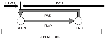 ⤢ zoomA repeat-loop timing diagram: F.FWD and RWD arrows above a timeline, a START circle and END circle joined by a horizontal PLAY arrow and a hooked RWD return path that runs up from END, left, then down into START, braced underneath and labeled REPEAT LOOP.
4.6 Test Oscillator↑ TOP
The MX-5050 includes a two-frequency Test Oscillator for use when recording reference tones for level matching or alignment purposes.
- Press the desired Oscillator Frequency button (1kHz or 10kHz) to activate the internal Test Oscillator.
- The test signal output from the oscillator is supplied to all channel inputs simultaneously. The signal input level can be adjusted by using the input level knob.