MX-5050 MKIV-2 and BIII-2 Operation and Maintenance Manual — Digital Edition · Part 3 · PDF pages 34-46
Controls and Indicators
This section describes the names and functions of the controls, indicators, and main components of the MX-5050. Drawings of the controls and indicators are used to associate the description with the real parts on the machine. When you have questions about any of the controls or their functions, please refer to this section.
This section includes the following sub sections.
| 3.1 | Tape Transport | 3-2 |
| 3.2 | Transport Control Panel | 3-3 |
| 3.3 | Head Assembly | 3-6 |
| 3.4 | Amplifier Panel | 3-7 |
| 3.6 | Audio Connector Panel | 3-9 |
| 3.7 | Connector Pin Assignments | 3-12 |
3.1 Tape Transport↑ TOP
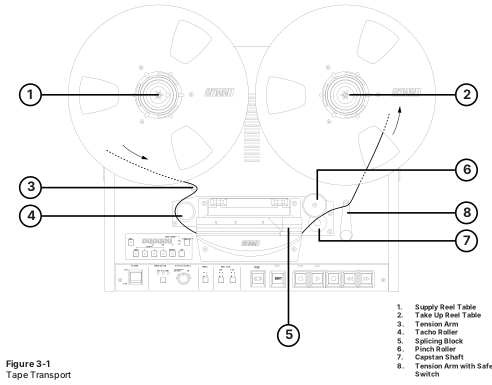 ⤢ zoomFigure 3-1 Tape Transport: a top-down view of the tape transport deck with the supply and take-up reels mounted above the head block and transport controls, eight numbered leader lines picking out the reel tables, tension arms, tacho roller, splicing block, pinch roller and capstan shaft.
Numbers in brackets [ ] refer to Figure 3-1.
[1] Supply Reel Table
[2] Take-up Reel Table
The Reel Tables are supplied with reel clamps for 5" or 7" reels. For 10.5 inch NAB reels, use the supplied reel adapter.
[3] Tension Arm
The Supply Tension Arm helps correct tape tension fluctuations due to changes in tape pack diameter or irregularities in tape pack.
[4] Tacho Roller
The Tacho Roller is turned by tape motion and generates tacho pulses which are used for the calculation of tape time and recognition of the tape direction.
[5] Splicing Block
When editing a tape, the tape is cut or spliced on this block.
[6] Pinch Roller
The tape is driven by the rotation of the Capstan Shaft against the Pinch Roller.
[7] Capstan Shaft
The Capstan Shaft is directly driven by a DC servo motor which is controlled by a quartz crystal reference in a phase-locked-loop circuit.
[8] Tension Arm with Safety Switch
The take-up tension arm is provided with a safety switch which stops the transport when the tape becomes unthreaded from the reel or when too much slack develops in the tape path.
3.2 Transport Control Panel↑ TOP
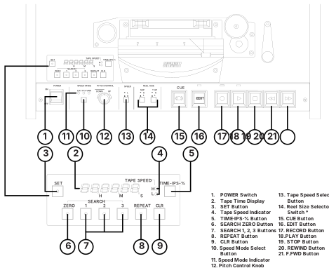 ⤢ zoomFigure 3-2 Transport Control Panel: the MX-5050's transport control panel in two views, the power, speed-mode, pitch-control, reel-size and transport-key row above and the enlarged tape-time display with its SEARCH/REPEAT/CLR keypad below, with twenty-one numbered leader lines keyed to the buttons and indicators listed beside it.
Numbers in brackets [ ] refer to Figure 3-2.
[1] POWER Switch
Pressing the upper portion of the Switch turns on the machine.
[2] Tape Time Display
This 6-digit display shows the tape time in Hours, Minutes, and Seconds; the tape speed in ips (inches per second); or the tape speed as a percentage change from the selected play speed, as set by the TIME·IPS·% Button [5].
[3] SET Button
Pressing this button initiates Set mode, in a desired value can be entered by using the SEARCH keys. There are two Set modes:
A. Cue Point Set mode: Refer to § 4.5.1
B. Vari Speed Set mode: Refer to § 4.4.6
[4] Tape Speed Indicator
This LED indicates the selected speed.
| Hi Version | Low Version (BIII-2) |
|---|---|
| Hi: 15 ips | Hi: 7.5 ips |
| Low: 7.5 ips | Low: 3.75 ips |
[5] TIME·IPS·% Button
Pressing this button causes the Tape Time display to show, in turn, the current tape time, the currently selected tape speed in ips, or the percentage of change from the currently selected tape speed.
Tape Time ➔ Tape Speed (ips) ➔ Speed Change (%) ➔ Tape Time ➔ ···
When the display is showing Tape Speed, "iP" appears in the rightmost column. Similarly, when in Speed Change is being displayed, "P" appears in the rightmost column.
[6] SEARCH ZERO Button
Pressing this key places the MX-5050 into Search Zero mode. In Search Zero mode the tape is moved at Fast Wind speed to the location of 00:00:00 and is then stopped.
[7] SEARCH 1, 2, 3 Buttons
Pressing one of the illuminated SEARCH keys moves the tape to the location stored in that SEARCH key and stops.
Storing a CUE point: Refer to § 4.5.1
Search Operation: Refer to § 4.5.2
Clearing a CUE point: Refer to [9] CLR key
[8] REPEAT Button
Pressing the REPEAT key, then pressing two SEARCH keys, then pressing the PLAY button enters the machine into Repeat mode. In Repeat mode, the machine repeatedly plays back the tape between two selected points. Refer to § 4.5.6. for details on Repeat mode.
[9] CLR Button
Pressing the CLR key together with the one of the following keys works as follows.
CLR + SET: Exits Set mode
CLR + T-IPS %: Tape Timer Display resets to zero
CLR + SEARCH 1-3: Cue Point Memory clears
CLR + REPEAT: Exits REPEAT mode
[10] Speed Mode Select Button
This button selects the tape speed for Record and Play modes. Pressing this button changes the Speed mode as follows.
- FIX mode: The Capstan Motor speed is controlled by the internal crystal oscillator. The speed setting (HI or LO) is selected by the Speed Select button.
- VARI mode: When the VARI mode is selected, the tape speed is changed by ± 20% of the nominal tape speed with the Pitch Control knob.
- EXT mode: Tape Speed is controlled by the external speed reference signal conveyed through the Parallel/O connector. When using a synchronizer or resolver, set the machine to this EXT mode.
NOTE: When the Speed Mode switch is set to the EXT position, the Tape Time display always shows tape time.
[11] Speed Mode Indicator
These indicators illuminate to show the speed mode selected with the Speed Mode Select Button.
[12] Pitch Control Knob
When the Speed Control mode is set to the VARI mode, the Pitch Control knob changes the tape speed in Record and Play modes. The tape speed is variable over a range of ± 20% of the selected FIX speed in 0.01 % steps.
[13] Tape Speed Select Button (HI/LO)
This button selects the speed setting of the machine. The following combinations are available. The speed version is set with SW1 on the CONTROL PCB.
| Machine Type | HI | LO |
|---|---|---|
| Hi Version Machine | 15ips | 7.5 ips |
| Low Version Machine | 7.5ips | 3.75 ips |
[14] Reel Size Change Switch
This switch sets the reel tension corresponding to the selected reel size. When using a 10.5" NAB Reel, set this switch to the "L" position. When using a reel smaller than 10.5", set the switch to the "S" position.
[15] CUE Button
Pressing this button during Fast Wind modes initiates Cue mode, in which the tape lifters retract allowing the tape to be in contact with the Reproduce head for audio monitoring at fast wind speed. There are two ways to enter CUE mode: tapping the CUE button or holding the CUE button down. For details, refer to § 4.2.1.
[16] EDIT Button
Pressing this button while in Stop mode causes the MX-5050 to enter Edit Ready mode, in which the take-up motor is turned off and the safety switch for the Take-up tension Arm is deactivated. Pressing the PLAY button in Edit Ready mode, or pressing the EDIT button in Play mode, causes the MX-5050 to enter Dump Edit mode, in which the Take-up reel does not rotate causing tape to be "dumped" from the transport.
[17] RECORD Button
When any channel is in Record Ready mode, pressing the RECORD and PLAY buttons simultaneously enters REC mode. Unless the READY/SAFE switch is placed at the READY position, actual recording will not take place. For Punch In/Out Operation, refer to §4.4.2.
[18] PLAY Button
Pressing this button when the transport is in Stop mode enters the tape into Play mode, in which the tape is reproduced at the currently selected tape speed. Pressing the PLAY button with the RECORD button enters the transport into Record mode.
[19] STOP Button
Pressing this button when the transport is in Record, Play, Dump Edit, Fast Forward or Rewind mode causes the tape motion to stop.
[20] REWIND Button
Pressing this button places the transport into Rewind mode, in which the tape moves from the Take-up reel to the Supply reel at Fast Wind speed.
[21] F.FWD Button
Pressing this button places the transport into Fast Forward mode, in which the tape moves from the Supply reel to the Take-up reel at Fast Wind speed.
3.3 Head Assembly↑ TOP
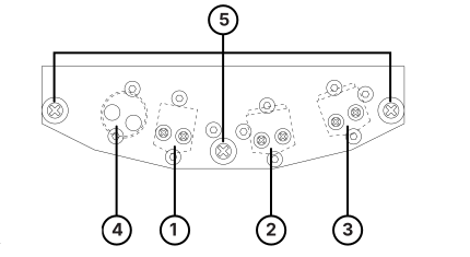 ⤢ zoomFigure 3-3 Head Assembly: the head block seen from the front, five numbered leader lines identifying the dummy head, erase head, record head, reproduce head and the head guides on either side.
Numbers in square brackets [ ] refer to Figure 3-3.
[1] Erase Head
The Erase Head is made of ferrite. The track width is 2 mm for the MKIV-2 and BIII2, 2.75 mm for the MKIV2E and BIII2E, and 6.3 mm for the BIII-F.
[2] Record Head
The Record Head is made of Hard Permalloy. The track width is 2 mm for the MKIV-2 and BIII2, 2.75 mm for the MKIV2E and BIII2E, and 6.3 mm for the BIII-F.
[3] Reproduce Head
The Reproduce Head is made of Hard Permalloy. The track width is 2 mm for the MKIV-2 and BIII2, 2.75 mm for the MKIV2E and BIII2E, and 6.3 mm for the BIII-F.
[4] Dummy Head (BQIII)
[5] Head Guides
These guides regulate the tape movement across the heads.
3.4 Amplifier Panel↑ TOP
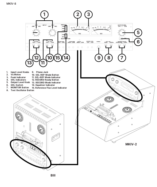 ⤢ zoomFigure 3-4 Amplifer Panel: the amplifier panel in three views — the MKIV-8 panel drawing on top with fifteen numbered leader lines keyed to the input, VU, peak, SRL, output, monitor and record controls listed below it, and the BIII and MKIV-2 recorders below that in three-quarter view with their own amplifier sections circled.
Numbers in square brackets [ ] refer to Figures 3-4 and 3-5.
[1] Input Level Knobs
The outer knob adjusts the line input signal level. The inner knob adjust the microphone input signal level.
[2] VU Meters
The VU meters indicate the record and reproduce levels of the associated channels. The VU meters illuminate when the machine is turned on.
[3] Peak Level Indicators (LED)
Each VU meter has a PEAK level indicator which illuminates when the signal reaches a level equivalent to 1040 nWb/m.
[4] SRL Indicator
This illuminates when the SRL button is pressed.
[5] Output Level Knob
The outer knob adjusts CH1 output signal level. The inner knob adjusts CH2 output signal level.
[6] SRL Switch
This switch selects the Standard Reference Level (SRL) of the output level. When this switch is pressed, the output level is set to the SRL (factory setting: +4dB).
[7] Monitor Button
This button selects the monitor signal source. When this button is set to SOURCE position, all the OUTPUT connectors and VU Meters receive the signal present at the INPUT connector. When this button is set to TAPE position, the signal reproduced with the Repro Head is output.
[8] Test Oscillator Buttons
Pressing one of these buuttons activates the test oscillator. The selectable oscillator frequencies are 1kHz and 10kHz.
[9] Monitor Phone Jack
This is the monitoring Head Phone Jack. Load Impedance is 8 Ω
[10] SEL-REP Mode Button
If the Monitor button is set to TAPE position and the SEL-REP Mode button is pressed, all the OUTPUT connectors and VU Meters receive signals reproduced by the Record head.
[11] SEL-REP Indicator
This indicator illuminates when the SEL-REP mode is selected.
[12] RECORD READY Buttons
When these buttons are pressed, the machine enters into READY mode. In READY mode, the machine enters Record mode when the REC and PLAY buttons are pressed. If these buttons have not been depressed, the machine is set to SAFE. In SAFE mode, the machine cannot enter Record mode even if the REC and PLAY buttons are pressed.
[13] RECORD Mode Indicator
This indicator illuminates when the machine is set to Record Ready mode.
[14] EQ indicator
This indicator illuminates to show the selected EQ setting.
[15] REF FLUX indicator
This indicator illuminates to show the selected Reference Flux Level.
3.6 Audio Connector Panel↑ TOP
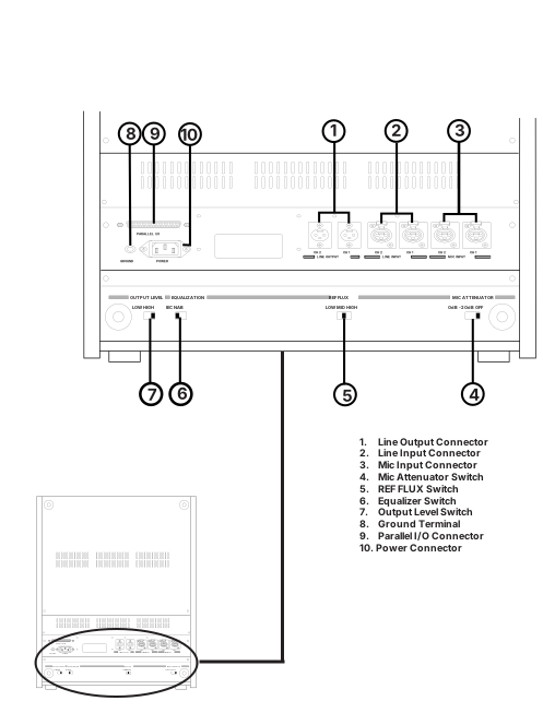 ⤢ zoomFigure 3-5 Audio Connector Panel (BIII): the BIII rear panel enlarged at top, its parallel I/O, ground, power, line and mic connectors and its output-level, equalization, REF FLUX and mic-attenuator switches keyed by ten numbered leader lines to the list beside it; below it, the whole BIII chassis seen from the rear, labeled the same way, with its connector and switch area ringed by an ellipse and tied by a leader line up to the enlarged view above.
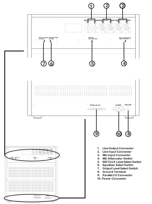 ⤢ zoomFigure 3-6 Audio Connector Panel (MKIV-2): the MKIV-2 rear panel enlarged in two strips — the line and mic connectors with the output-level, equalization, REF FLUX and mic-attenuator switches above, keyed to callouts 1-7, and the parallel I/O connector with the power and ground terminals below, keyed to callouts 8-10; at bottom left, the whole MKIV-2 chassis seen from the rear with two ellipses ringing those same two areas, each tied by a leader line up to its enlarged strip.
The numbers in bracket [ ] refer to Figures 3-7 and 3-8.
[1] LINE OUTPUT Connector
These XL type connectors are for audio output. See §2.2.2 for pin assignment.
[2] LINE INPUT Connector
These XL type connectors are for audio input. See §2.2.2 for pin assignment.
[3] Microphone Input Connector
These XL type connectors are for microphone input.
[4] Microphone Attenuator Switch
When this switch is set to the –20dB position, this switch attenuates the microphone input level by 20dB. If attenuation is not necessary, set this to 0dB. When this switch is set to the OFF position, the MIC input is not active.
[5] REF FLUX Switch
This switch selects the Reference Flux Level from L(185)/M (250)/H (320 nWb/m).
[6] Equalizer Switch
This switch changes the Equalizer setting to IEC or NAB.
[7] Output Level Switch
This switch selects the output level from +4dBu/-16dBu.
[8] GROUND Terminal
This is the auxiliary ground terminal. Connect equipment not connected to the AC earth to this terminal.
[9] POWER Connector
This connector is for the supplied AC power cable.
[10] PARALLEL I/O Connector
This is the OTARI standard Parallel I/O connector. This 37 pin connector includes ports for Transport Control Command Status Tally Signal and External Capstan Speed Control Signal. For details refer to § 3.7.
3.7 Connector Pin Assignment↑ TOP
Table 3-1
Parallel I/O Pin Assignment
| No. | Signal Name | Signal Level | IN/OUT | Function |
|---|---|---|---|---|
| 1 | RECORD SW | LOW | IN | RECORD Switch |
| 2 | PLAY SW | LOW | IN | PLAY Switch |
| 3 | STOP SW | LOW | IN | STOP Switch |
| 4 | F.FWD SW | LOW | IN | F.FWD Switch |
| 5 | REWIND SW | LOW | IN | RWD Switch |
| 6 | LIFTER DEFEAT | LOW | IN | Lifter Defeat Switch |
| 9 | SAFETY SW SHUT OFF | LOW | OUT | Safety Switch |
| 10 | RECORD TALLY | LOW | OUT | Record Tally |
| 11 | PLAY TALLY | OUT | Play Tally | |
| 12 | STOP TALLY | LOW | OUT | Stop Tally |
| 13 | F.FWD TALLY | LOW | OUT | F.FWD Tally |
| 14 | REWIND TALLY | LOW | OUT | RWD Tally |
| 16 | SIGNAL GROUND | LOW | Signal GND | |
| 17 1 | TACHO PULSE | OUT | Tacho Pulse Output | |
| 18 | FWD/REV | LOW/HI | OUT | Tape Direction |
| 19 | 9.6kHz (FIX) | OUT | 9.6 kHz Output | |
| 20 2 | CAP.CLOCK | IN | Ext Speed CNT Input | |
| 21 3 | SPEED A | LOW/HI | OUT | |
| 22 3 | SPEED B | LOW/HI | OUT | |
| 23 | PITCH ENABLE | LOW | IN | EXT. Speed CNT Command |
| 24 | PITCH TALLY | LOW | OUT | EXT CNT Tally |
| 25 | REC. READY | LOW | OUT | REC READY Tally |
| 31 | SENSOR TALLY | LOW | OUT | Proximity Sensor |
| 32 | REHEARSE | LOW | IN | REC Rehearsal Command |
| 33 | 5V ± 10% | 5V (max 150 mA) | ||
| 34 | AUX. POWER | Unreg. Power Output | ||
| 35 | AUX. POWER | (24V ~ 40V Max. 500mA) | ||
| 36 | POWER GND | Power GND | ||
| 37 | POWER GND | Power GND |
1 Tacho pulse
Tacho Pulse Rate
| 15 ips | 120 pulse/sec |
| 7.5 ips | 60 pulse/sec |
| 3.75 ips | 30 pulse/sec |
Tacho Pulse Width
Minimum 100µsec
2 CAP. CLOCK
Capstan Ext. Speed Control Input Clock
Rated Tape Speed: 9.6kHz
Allowable Frequency Range: 4.8 to 19.2kHz
Duty Cycle: 40 to 60 %
3 SPEED A, SPEED B
Table 3-2
Connector Pin 21,22
| TAPE SPEED | SPEED A | SPEED B |
|---|---|---|
| 15 ips | High | Low |
| 7.5 ips | Low | High |
NR Remote Connector (MKIV-8 Option)
Table 3-3
Remote Control Connector (MKIV-8 Option)
| CH | PIN | CH | PIN |
|---|---|---|---|
| CH1 | 1 - 14 | CH5 | 5 - 18 |
| CH2 | 2 - 15 | CH6 | 6 - 19 |
| CH3 | 3 - 16 | CH7 | 7 - 20 |
| CH4 | 4 - 17 | CH8 | 8 - 21 |