MX-5050 MKIV-2 and BIII-2 Operation and Maintenance Manual — Digital Edition · Part 2 · PDF pages 18-32
Installation
This section of the manual provides information on unpacking and inspecting the tape recorder, and on power and signal connections. Refer to this section when first setting up the machine.
This section includes the following sub sections.
| 2.1 | Unpacking and Inspection | 2-2 |
| 2.2 | Audio Signal Connection | 2-3 |
| 2.2.1 | Audio Connectors | 2-3 |
| 2.2.2 | Balance/Unbalance Adjustment | 2-4 |
| 2.3 | Switch Position Adjustment | 2-5 |
| 2.4 | PCB Assembly Location | 2-9 |
| 2.4.1 | MX-5050 BIII | 2-9 |
| 2.4.2 | MX-5050 MKIV2 | 2-11 |
| 2.5 | Power Connection | 2-13 |
| 2.6 | Fuse Replacement | 2-14 |
| 2.7 | Speed Conversion (BIII-2) | 2-15 |
| 2.8 | Equalizer Change | 2-15 |
2.1 Unpacking and Inspection↑ TOP
After receiving the MX-5050, examine the case for any signs of damage. Then unpack and inspect the equipment. Take care when unpacking the equipment and removing packing materials to prevent damaging the critical components such as the capstan, head assembly, and tension arms. If there is any evidence of damage due to rough handling during transportation, a claim should be filed with the transportation company. We recommend retaining the packing material at least until proper operation of the machine has been established.
Verify that all items, as listed in Table 2-1, have been received. Do not connect or operate the MX-5050 until this inspection has been completed.
When sending the machine back to the local OTARI dealer or to OTARI, follow the packing directions printed on the carton.
Table 2-1
Standard Accessories
MX-5050 BIII, MKIV-2
| Parts Name | Part No. | Quantity |
|---|---|---|
| Reel Clamp | KW0HV | 2 |
| Power Cable | PZ9D003 | 1 |
| Manual | OS3-298 | 1 |
| Lubrication Oil | PZ9E003 | 1 |
| Fuse 1A | FH7F010 | 1 |
| (Fuse 1A 200-240V only | FH9-032 | 1) |
| Fuse 2A | FH9-030 | 1 |
| Fuse 2A | FH7F020 | 1 |
| Fuse 3A | FH7F030 | 1 |
| Fuse 4A | FH7F040 | 1 |
| Fuse 5A | FH7F050 | 1 |
2.2 Audio Signal Connection↑ TOP
2.2.1 Audio Connectors↑ TOP
The input to the machine is transformerless and balanced with an input impedance of 10 kΩ. The input level is fixed to +4dBu.
The output from the machine is transformerless and balanced. The nominal output level is selected from +4 dBu or -16 dBu with the switch on the rear panel. The output level is set to +4 dBu at the factory.
The microphone input is balanced with an input impedance of 10 kΩ. Input level can be attenuated by 20 dB with the attenuation switch on the rear panel.
The connections to the Input/Output connectors are as shown in Figure 2-1.
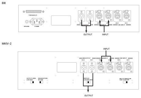 ⤢ zoomFigure 2-1 Input/Output Connectors: two labeled rear-panel diagrams, the BIII connector panel above and the MKIV-2 connector panel below, each with bold INPUT and OUTPUT arrows pointing to the PARALLEL I/O, LINE OUTPUT, LINE INPUT and MIC INPUT connectors.
2.2.2 Balanced/Unbalanced Connection↑ TOP
The Input/Output connectors are balanced as shown in Figure 2-2. The pin assignment of the connectors is as follows:
Pin 1: Shield (GND)
Pin 2: Cold
Pin 3: Hot.
When connecting an unbalanced machine to the MX-5050, change the pin assignment as shown in Figure 2-2.
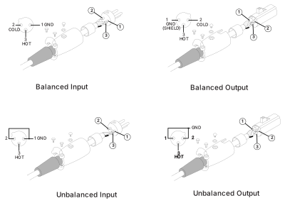 ⤢ zoomFigure 2-2 Balanced/Unbalanced Connectors: four numbered 3-pin wiring diagrams — Balanced Input, Balanced Output, Unbalanced Input and Unbalanced Output — each showing how pins 1 (GND/shield), 2 (cold) and 3 (hot) are connected between the XLR connector and the phone plug.
Optional Input (ZA-53T)/Output (ZA-53S) Transformers are available from OTARI. For details contact OTARI or your nearest OTARI dealer.
2.3 Switch Position Adjustment↑ TOP
If necessary, change the following switch settings on the rear panel before operating the machine.
Table 2-2
Settings on Rear Panel
| Function | Switch | Setting |
|---|---|---|
| MIC. Attenuator | SW501 | 0dB/-20dB/OFF |
| REF FLUX | SW502 | H/M/L (320/250/185nWb/m) |
| EQ Setting | SW503 | NAB/IEC |
| Output Level Setting | SW504 | H: +4dBu, L: -16dBu |
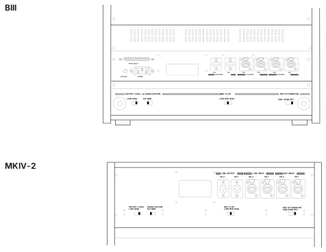 ⤢ zoomFigure 2-3 Switch Settings on Rear Panel: the BIII and MKIV-2 rear panels, each showing the OUTPUT LEVEL, EQUALIZATION, REF FLUX and MIC ATTENUATOR switches alongside the PARALLEL I/O, LINE and MIC connectors.
- DIP SW settings on the CONTROL PCB
Table 2-3
DIP SW Settings on the Control PCB
Note: When any of the following DIP SW settings are changed, the machine must be turned off and on for the settings to take effect.
| SW1 | SW2 |
|---|---|
| SW1-1 Speed Version | SW2-1 SEARCH 3 key Selection |
| SW1-2 Punch-In | SW2-2 SEARCH 3 key Selection |
| SW1-3 Punch-Out | SW2-3 Stop Mute Selection |
| SW1-4 Capstan PLL Reference | SW2-4 Fast Wind Mute Selection |
| SW1-5 Capstan PLL Reference | SW2-5 Play Start Mute |
| SW1-6 Punch-In Type Select | SW2-6 Machine Type |
| SW1-7 REC LED Flashing Select | SW2-7 Machine Type |
| SW1-8 External Control Select | SW2-8 Not used |
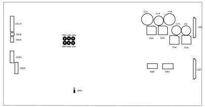 ⤢ zoomFigure 2-4 Controls on the CONTROL PCB Assembly: a top-down drawing of the CONTROL PCB Assembly with its connectors CN3, CN7, CN23, CN24, CN25, CN26 and CN 27 (printed with a space), capacitors C9, C10, C18, C19 and C21, diodes D43, D44, D45 and D46, trimmers VR1, VR2, VR3, VR4, VR5 and VR6, and DIP switches SW1, SW2 and SW3 labeled in their board positions.
Refer to Fig 2-4 for the location of these DIP switches on the CONTROL PCB Assembly.
SW1-1 Speed Version Selection (BIII-2)
ON 3.75/7.5 ips: Low Speed Version (Option)
OFF 15/7.5 ips: High Speed Version
The BIII-2 is set to High Speed at the factory. After receiving the BIII-2, it can be changed to Low Speed with this switch. Refer to §2.8 for details. The MKIV-2 cannot be changed to Low Speed.
SW1-2 Punch-In (Refer to § 3.2, [18] REC button)
ON Press REC and PLAY buttons in PLAY mode to begin Punch-In
OFF Press REC button in PLAY mode to begin Punch-In
SW1-3 Punch-Out (Refer to § 3.2, [19] PLAY button)
ON Press PLAY button to end the Punch-In Record
OFF Press STOP and REC button to end the Punch-In Record
SW1-4, 1-5 Capstan PLL Reference Setting
When the machine is in FIX mode, the capstan speed is adjusted with these switches (refer to § 6.7).
Table 2-4
Capstan PLL Reference Setting
| SW1-4 | SW1-5 | OFF SET (%) |
|---|---|---|
| ON | ON | + 0.2% |
| OFF | ON | – 0.2% |
| ON | OFF | – 0.4% |
| OFF | OFF | Not used |
SW 1-6 Adding Punch In Type Selection
 ⤢ zoomEdge Type Punch In command signal: an unlabeled timing waveform stepping down then back up, with a downward arrow marking the falling edge that triggers Punch-In.
ON Edge Type
With this setting, the Punch In command signal is as shown above. Additional Punch-Ins are made by pressing the PLAY and REC buttons (or just the REC button) while in Ready mode.
 ⤢ zoomLevel Type Punch In command signal: an unlabeled timing waveform stepping up then down, with a downward arrow marking the level transition that triggers Punch-In.
OFF Level Type
With this setting, the Punch In command signal is as shown above. Additional Punch-Ins are made by changing READY/SAFE switches from the SAFE position to the READY position.
SW1-7 Flashing REC button selection
This switch selects whether the lamp on the REC button flashes when the READY/SAFE switch is set to READY.
ON Illuminates (does not flash)
OFF Flashes
SW1-8 \
SW2-1, 2-2
These switches select the function of the SEARCH 3 key.
Table 2-5
SEARCH 3 Key Function
| SW2-1 | 2-2 | Function |
|---|---|---|
| ON | ON | Proximity Sensor ON/OFF key * |
| OFF | ON | Not used |
| ON | OFF | Search Start (§ 4.5.6) |
| OFF | OFF | Search Cue (§ 4.5.3) Default Setting |
* When using the optional proximity sensor, pressing the SEARCH 3 key enables/disables the Proximity Sensor Function.
SW2-3
This switch selects whether the audio signal is muted during the time from when the STOP button is pressed until the machine actually stops.
ON: Not Mute
OFF: Mute
SW2-4
This switch selects whether the audio signal is muted during Fast Wind modes other than Fast Wind Cue mode.
ON: Not Mute
OFF: Mute
SW2-5
This switch selects whether the audio is muted during the time from when the PLAY button is pressed until the tape enters Play mode.
ON: Not Mute
OFF: Mute
SW2-6, 2-7
These switch settings determine the machine type. These switches are set at the factory and should not be changed.
Table 2-6
Machine Type
| SW2-6 | SW2-7 | Type | Tape | Rehearsal | Size |
|---|---|---|---|---|---|
| ON | ON | 8CH | 1/2" | O | O |
| OFF | ON | 4CH | 1/2" | O | O |
| ON | OFF | 4CH | 1/4" | O | O |
SW2-8
Not Used
2.4 PCB Assembly Location↑ TOP
2.4.1 MX-5050 BIII↑ TOP
The PCB Assemblies are located as shown in Figure 2-5. The CONTROL PCB Assembly is accessed by removing the rear panel. (Refer to Figure 2-9). The CONTROL PCB can be rotated to adjust parts on the COMP side. To access the REC/ REP AMP PCB Assembly, the AMP section of the MX-5050BIII must be turned face up. The rotation of the AMP section is performed as follows.
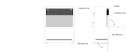 ⤢ zoomFigure 2-5 PCB Assembly Location (BIII): front and side views of the BIII cabinet with the CONTROL PCB and REC/REP PCB locations labeled, and the rear-panel SCREW that secures the CONTROL PCB.
- AMP Section Rotation
-
Turn off the machine. Place the machine so that the transport faces upward. Refer to Figure 2-6.
-
Remove the four screws holding the Bottom Cover. Remove the Bottom Cover from the machine.
-
Remove the four screws holding the AMP section. While lifting the AMP section slightly, rotate it to a horizontal position.
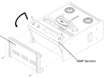 ⤢ zoomFigure 2-6 AMP Section Rotation: an exploded view of the BIII transport with the Bottom Cover and the AMP Section labeled, and a curved arrow showing the AMP section rotating down into its horizontal service position.
- CONTROL PCB Assembly Rotation
-
Turn off the machine. Place the machine in the upright position. See Figure 2-7.
-
Remove the Foot and Deck Stand from the Rear Cover.
-
Remove the Rear Cover by removing the screws holding it in place.
-
Loosen the two screws holding the Heat sink. Rotate the CONTROL PCB Assembly on its side.
-
The Side Boards may need to be removed to access some controls on the CONTROL PCB Assembly.
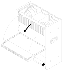 ⤢ zoomFigure 2- 7 CONTROL PCB Assembly Rotation: the BIII cabinet from the rear with the CONTROL PCB Assembly's mounting arc drawn in dashed lines and an arrow showing it swinging out to its rotated service position.
2.4.2 MX-5050 MKIV2↑ TOP
The AMP section of the MKIV-2 is adjusted after removing the Top Panel.
- Accessing the AMP Section
-
Turn off the machine. Remove the Top Panel (for MKIV-2).
-
Adjust the PCB Assemblies (REC/REP AMP PCB Assembly) located inside the AMP section.
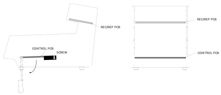 ⤢ zoomFigure 2-8 PCB Assembly Location: side and rear views of the MKIV-2 chassis with the CONTROL PCB, its mounting SCREW, and the REC/REP PCB labeled in their positions.
- CONTROL PCB Assembly Rotation
Follow the steps below when adjusting the CONTROL PCB Assembly and internal parts of the MKIV-2.
-
Turn off the machine. Lay the machine on its side.
-
Remove the Bottom Panel by removing the screws holding it.
-
Loosen the two screws holding the Heat Sink on the Control PCB Assembly. Rotate the CONTROL PCB Assembly.
-
Depending on the parts to be adjusted, the side panel may also need to be removed.
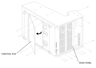 ⤢ zoomFigure 2-9 CONTROL PCB Assembly Rotation (MKIV-2): a rear three-quarter view of the MKIV-2 chassis with the REAR PANEL removed and the CONTROL PCB shown swung open on its hinge, held by its mounting screws.
2.5 Power Connection↑ TOP
Confirm that the power voltage marked on the rear panel corresponds with the line voltage being used.
- Turning on the machine
For power connection, use the included Power Cable. Connect the Power Cable plug to the power connector located at the rear of the machine. Make sure that the machine is turned off before connecting the other end of the power cable to the AC line outlet. The machine is now ready to be turned on.
Pressing the upper portion of the POWER Switch applies power to the machine. After power is applied to the machine, the VU meters, tape timer digits, and the indicator above the STOP button will illuminate. The Tape Timer will show the selected tape speed for several seconds after the machine is turned on, and then will change to tape time indication.
Turning on the machine while pressing the STOP button will cause the ROM version of the Control PCB Assembly to be displayed.
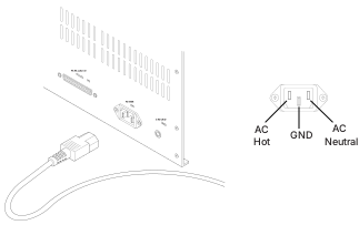 ⤢ zoomFigure 2-10 Power Connection: the rear panel power inlet with its Power Cable plugged in, and an inset pinout of the AC connector showing AC Hot, GND and AC Neutral.
- AC Voltage Connector Replacement
When the AC Line Voltage is different from the factory setting, the Line Voltage connector should be changed to the proper one. In this case, contact OTARI or nearest OTARI dealer and order the proper Line Voltage connector. The Line Voltage connector (white) is located beside the Supply Reel Motor. First remove the rear panel and replace it. The following figure describes the wiring of the connectors.
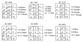 ⤢ zoomFigure 2-11 AC Line Voltage Connector: six 12-pin connector wiring diagrams, one for each line voltage, each numbering its twelve pins and listing which pins are jumpered together by colored wires: AC 100V jumpers 1-9, 4-12, 7-8 and 10-11 with brown wires; AC 110V jumpers 1-3, 4-6, 7-8 and 10-11 with red wires; AC 117V jumpers 1-2, 4-5, 7-8 and 10-11 with orange wires; AC 200V jumpers 1-9, 8-12 and 10-11 with yellow wires; AC 220V jumpers 1-3, 6-8 and 10-11 with green wires; AC 240V jumpers 1-2, 5-8 and 10-11 with blue wires.
2.6 Fuse Replacement↑ TOP
If a fuse is blown, first check the cause of the blown fuse, then replace the fuse with a new one as follows.
CAUTION: For continued protection against fire hazard, replace only with the same type of fuse. Before replacing a fuse, disconnect the power cable from the AC line.
First refer the Table 2-1 for information on the eight fuses.
Replacement of the Main Fuses
-
Remove the left side panel by removing the screws holding it.
-
Referring to the Figure 2-11, find the fuse location.
-
Locate the blown out fuse(s).
-
Replace the blown out fuse(s) with a new one(s).
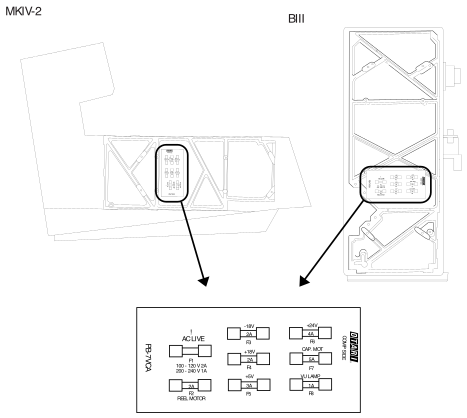 ⤢ zoomFigure 2-12 Fuse Location: MKIV-2 and BIII chassis drawings with the fuse block (COMP SIDE) circled and called out, plus a detail view of the PB-7VCA fuse board: F1 AC LIVE (100 - 120 V 2A / 200 - 240 V 1A), F2 REEL MOTOR 2A, F3 -18V 2A, F4 +18V 2A, F5 +5V 3A, F6 +24V 4A, F7 CAP. MOT 5A, F8 VU LAMP 1A.
Table 2-7
Fuse Specifications
Rating
| Number | Current | Voltage | Size | Carry | Otari No. | Used For |
|---|---|---|---|---|---|---|
| F1 | 2A | 125V | 5.2 x 20mm | 110% | FH9-030 | Power Supply |
| F2 | 2A | 125V | 5.2 x 20mm | 110% | FH7F020 | Reel Motor |
| F3 | 2A | 125V | 5.2 x 20mm | 110% | FH9-030 | –18V (Slow Blow) |
| F4 | 2A | 125V | 5.2 x 20mm | 110% | FH9-030 | +18V (Slow Blow) |
| F5 | 3A | 125V | 5.2 x 20mm | 110% | FH7F030 | +5V |
| F6 | 4A | 125V | 5.2 x 20mm | 110% | FH7F040 | +24V |
| F7 | 5A | 125V | 5.2 x 20mm | 110% | FH7F050 | Capstan Motor |
| F8 | 1A | 125V | 5.2 x 20mm | 110% | FH7F010 | VU Lamp |
2.7 Speed Conversion (BIII-2)↑ TOP
Normally, the MX-5050 BIII-2 is shipped from the factory with set at High Speed (15/7.5 ips). If you want to change this to Low Speed (7.5/3.75 ips), follow the steps below.
-
Remove the bottom panel to access the CONTROL PCB. Rotate the CONTROL PCB.
-
The Speed Version Select SW1-1 is located on the CONTROL PCB. Change the switch position to the LOW position. (Refer to § 2.3.)
-
Replace the bottom panel on the machine.
-
Make all necessary adjustments (Reproduce EQ, SRL, Bias Record EQ, Record Level) referring to the corresponding explanation in Section 7.
NOTE: The MX-5050 MKIV-2 cannot be changed to Low Speed.
2.8 Equalization Change↑ TOP
The Equalization type is set to the customer's specifications at the factory. The setting can be changed between NAB and IEC by sliding the EQUALIZER select switch on the rear panel (Refer to § 2.3). If the setting is changed, equalizer adjustments (§ 7.3.3 and 7.4.5) must be made.