BQ-II Instruction and Maintenance Manual — Digital Edition · Part 2 · PDF pages 17-23
Installation
This section of the manual provides information on unpacking and inspection, location and environment, and power and signal connections.
2-1 UNPACKING AND INSPECTION↑ TOP
The MX-5050 BQII system is shipped from the factory in a single cardboard packing case.
Upon receipt, examine the case for any sign of damage. Unpack the equipment and inspect for any sign of damage.
Use great care when unpacking the equipment and removing packing materials to prevent damage to critical components such as the capstan, head assembly, and tension arms.
Referring to Table 1-1 and Table 1-2 (as applicable), verify that all items have been received.
Report any shortage or damage to the carrier and your local Otari dealer.
Save the packing case for possible shipment of the equipment to another location or in case of reshipment.
Other packaging may cause damage during transportation and will void the warranty.
Regarding the repacking method, please refer to the illustration which is attached to a flap of the packing box.
2-2 LOCATION AND ENVIRONMENT↑ TOP
The area chosen for operation should be adequately ventilated and dust free.
Since recording is by an electromagnetic process, it is possible that strong electromagnetic fields may affect the system adversely.
Common sources of interference are fluctuating loads on nearby high voltage lines, heavy duty transformers, transmitting equipment, and air conditioners.
It is recommended that the equipment be used in an environment where the surrounding temperature does not exceed limits of 40° to 104°F (5° to 40° C), with the relative humidity between 20 and 80%.
Allow at least a 4 inch (approx. 10 cm) clearance behind the rear panel
2-3 DIMENSIONS↑ TOP
Dimensions of the MX-5050 BQII are shown in Figure 2-1.
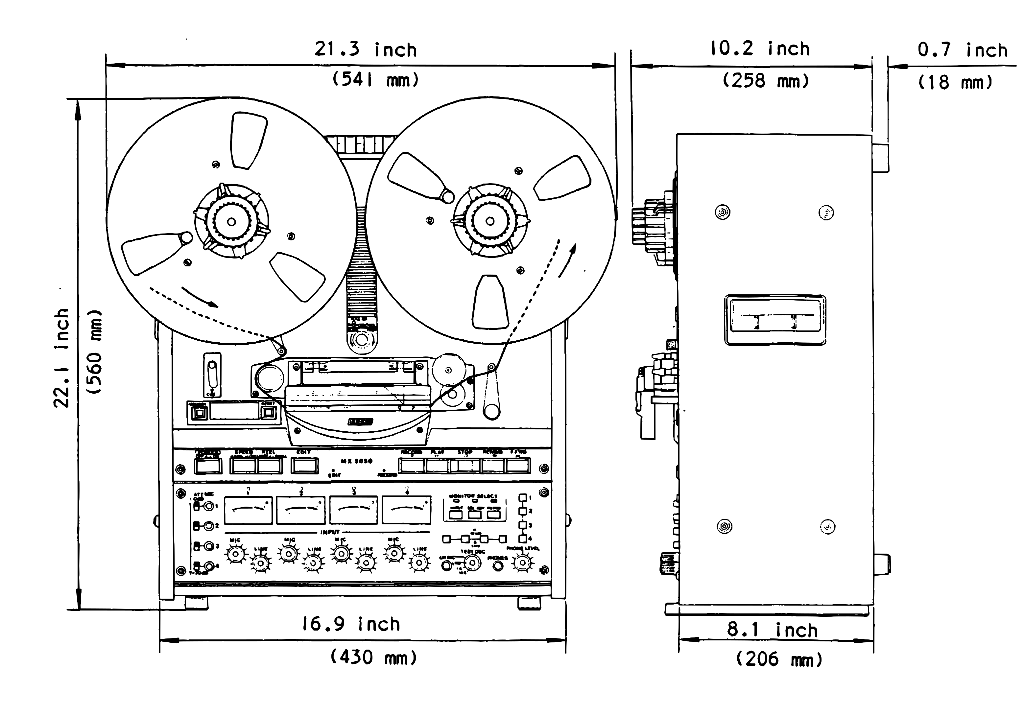 ⤢ zoomFront and side elevation drawings of the MX-5050 BQII with its overall dimensions: 21.3 inch (541 mm) wide, 22.1 inch (560 mm) high and 10.2 inch (258 mm) deep plus 0.7 inch (18 mm) at the rear, standing on feet 16.9 inch (430 mm) apart across and 8.1 inch (206 mm) front to back.
Figure 2-1 Dimensions
2-4 OPERATING POSITION↑ TOP
The MX-5050 BQII can be operated at an angle by using the tape deck stand.
Maximum cooling efficiency is obtained when the unit is set vertically •
Although the MX-5050 BQII can be operated vertically or at an angle by using the tape deck stand, when it is operated vertically, nothing should be placed on the top of the recorder or within 4 inch (approx. 10 cm) of the back to aid ventilation.
The tape deck stand is installed on the rear cover by four screws.
To position the MX-5050 BQII at an angle, press both sides of the tape deck stand as shown in Figure 2-2 and pull out to an angle of 90° to set.
To retract the tape deck stand, proceed in the reverse order.
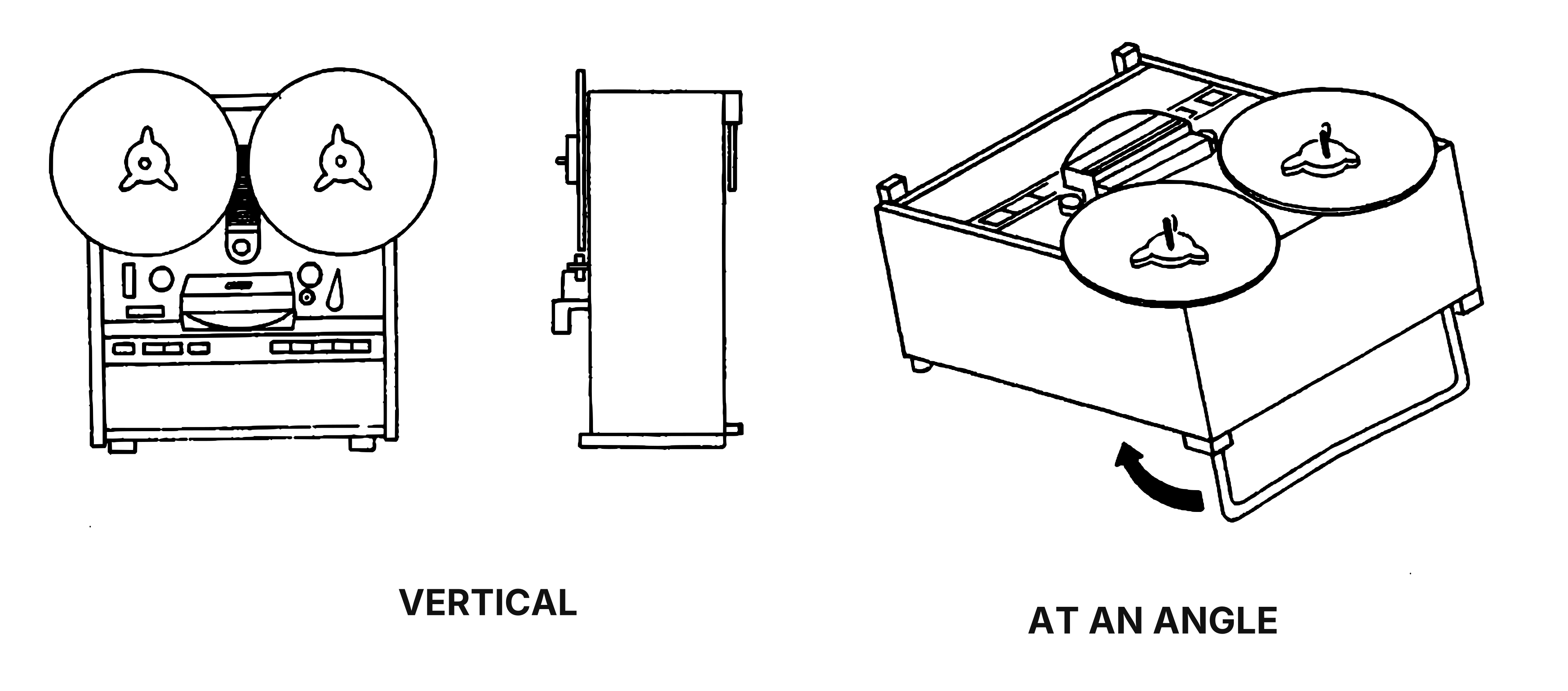 ⤢ zoomSketches of the recorder standing upright, seen from the front and the side, under VERTICAL, and tilted back on its fold-out rear stand, with an arrow showing the stand swinging out, under AT AN ANGLE.
Figure 2-2 Operating Position
2-5 STANDARD SWITCH POSITION ON SHIPMENT↑ TOP
LINE INPUT LEVEL and OUTPUT LEVEL switches are provided on the adjusting panel in the record/reproduce electronics and the MIC attenuator switches are provided on the front panel of the electronics on the MX-5050 BQII.
These switches have been set at the factory at one of two positions as shown in Table 2-1.
Slide the switch to the desired position to change the standard.
Table 2-1. Standard Switch Position on shipment
| SWITCH | Ref. No | POSITION |
|---|---|---|
| LINE INPUT LEVEL | 1 | L (minimum -18 dBm) |
| LINE OUTPUT LEVEL | 2 | H (+4 dBm) |
| MIC ATT | 3 | 0 dB |
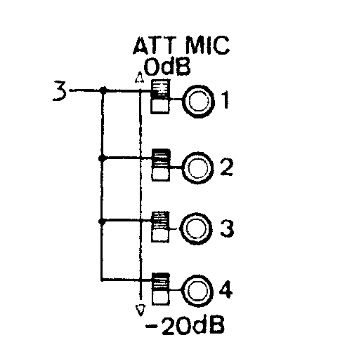 ⤢ zoomThe four MIC ATT slide switches beside the channel 1 to 4 microphone jacks, marked 0dB in the upper position and -20dB in the lower, with callout 3 pointing to the switches.
Figure 2-3 MIC ATT
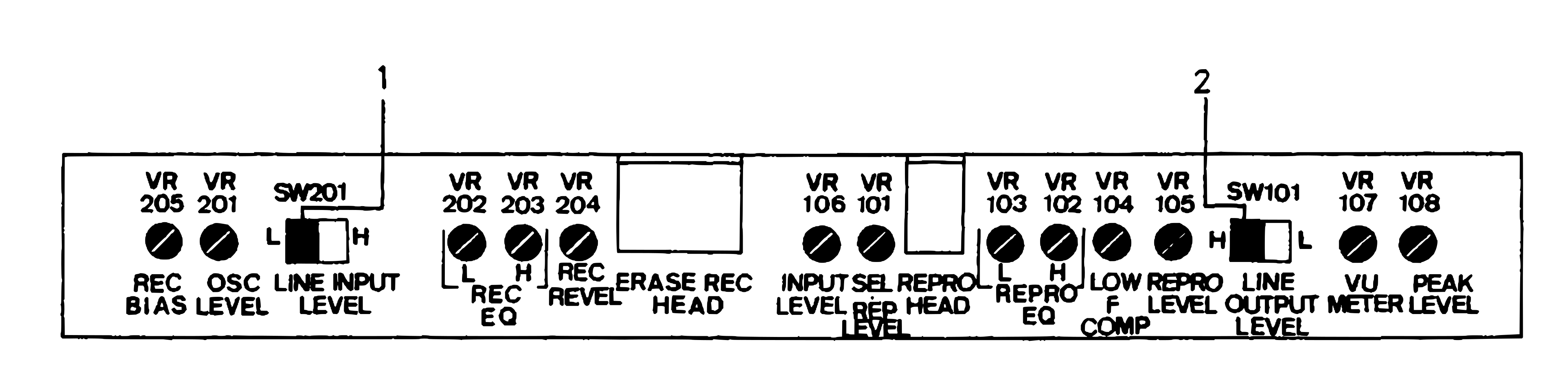 ⤢ zoomThe adjusting panel's row of trimmers and switches from VR205 REC BIAS to VR108 PEAK LEVEL, with callout 1 on the SW201 LINE INPUT LEVEL L/H switch and callout 2 on the SW101 LINE OUTPUT LEVEL H/L switch.
Figure 2-4 Adjusting Panel
2-6 POWER AND SIGNAL CONNECTIONS↑ TOP
Power, auxiliary ground, remote, and line input/output connections are made on the rear connector panel of the MX-5050 BQII
Table 2-2 shows the function of each connector and component on the rear panel.
Table 2-2 Rear Connector Panel
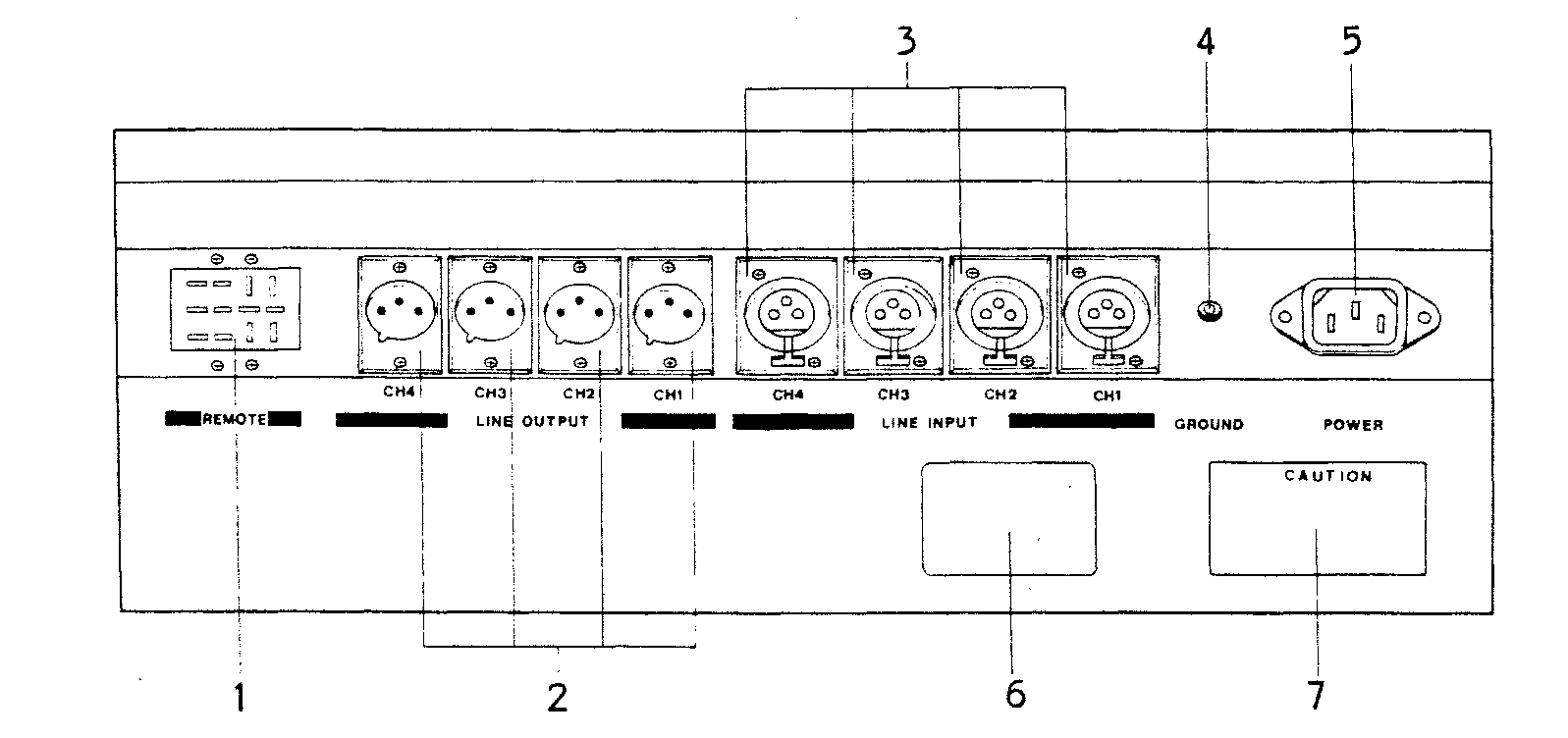 ⤢ zoomRear connector panel with numbered callouts: 1 the REMOTE connector, 2 the four LINE OUTPUT male XLR connectors, 3 the four LINE INPUT female XLR connectors, 4 the GROUND terminal, 5 the POWER inlet, 6 the name plate and 7 the CAUTION label.
| Index No. | Name | Function |
|---|---|---|
| 1 | REMOTE CONTROL connector | Used to connect optional remote control unit (CB-102). |
| 2 | LINE OUTPUT connectors | Male XLR connector with unbalanced output. load impedance : 600 ohm or greater level : +4 or -8 dBm at 0 VU, selectable with on-board switch Maximum output level: +21 dBm with a 600 ohm load |
| 3 | LINE INPUT | Female XLR connector with un-connectors balanced input. Input impedance: 50 kohm Minimum input: -6 dBm or -18 dBm, selectable with on-board switch. |
| 4 | GROUND terminal | Auxiliary ground connection for use with equipment not connected to a common ac ground. |
| 5 | POWER connector | Three-terminal connector for connection to ac power and ground. |
| 6 | PRODUCTION name plate | Indicates model number, production lot number (serial number), power requirements, and place of manufacture. |
| 7 | CAUTION | Precautions for preventing fire and shock. |
2-6-(1) AC POWER CONNECTION↑ TOP
The MX-5050 BQII is factory set to operate at the line voltage and frequency indicated on the packing case and on the rear connector panel of the equipment.
AC power is connected by means of a three-wire power cable which also provides a common ground connection.
If a two-wire receptacle is used with an adaptor, be sure the adaptor is properly grounded.
If a change of line voltage is desired to accommodate different power requirements, please contact your nearest Otari dealer.
2-6-(2) SIGNAL CONNECTIONS↑ TOP
Line input (female) and line output (male) connectors are XLR-type connectors.
To wire the mating plugs, refer to Figure 2-5 and proceed as follows.
LINE INPUT CONNECTOR WIRING:
For unbalanced inputs using two-conductor shielded cable, wire the male XLR-connector as follows:
- Connect the signal leads of a cable to pin 3 (high) and pin 2 (low) of the connector.
- Connect the cable shield to pin 1 of the connector.
- Connect a jumper from pin 1 to pin 2 of the connector.
For unbalanced inputs using single-conductor shielded cable, wire the male XLR connector as follows:
- Connect the center conductor of the single-conductor shielded cable to pin 3 of the connector.
- Connect the cable shield to pins 1 and 2.
LINE OUTPUT CONNECTOR WIRING
For unbalanced outputs using two-conductor shielded cable, wire the female XLR-connector as follows:
- Connect the signal leads of the cable to pin 3 (high) and pin 2 (low) of the connector.
- Connect the cable shield to pin 1 of the connector.
- Connect a jumper from pin 1 to pin 2 of the connector.
For unbalanced outputs using single-conductor shielded cable, wire the female XLR-type connector as follows:
- Connect the center conductor cable to pin 3 of the connector.
- Connect the cable shield to pin 2 of the connector.
- Connect a jumper between pins 1 and 2 of the connector.
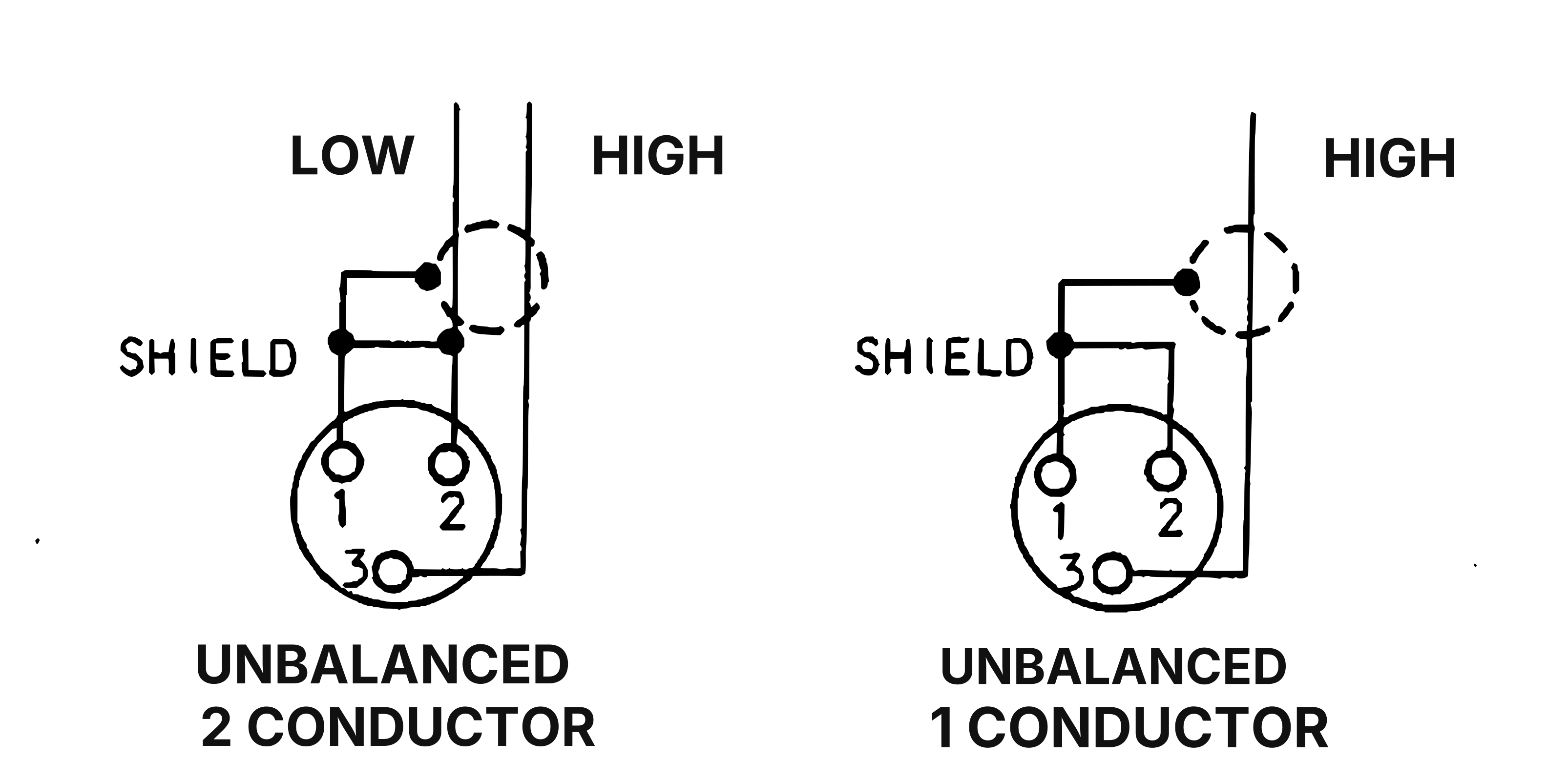 ⤢ zoomWiring of an XLR connector for two cases: UNBALANCED 2 CONDUCTOR, with HIGH to pin 3, LOW to pin 2 and the shield to pin 1, jumpered to pin 2; and UNBALANCED 1 CONDUCTOR, with HIGH to pin 3 and the shield to pins 1 and 2.
Figure 2-5 Input/Output Assembly Connector Wiring