BQ-II Instruction and Maintenance Manual — Digital Edition · Part 3 · PDF pages 24-36
Operation
This section of the manual provides a description of all operating controls and indicators and their use in the system, and step-by-step procedures for the various modes of operation.
3-1 CONTROLS AND INDICATORS↑ TOP
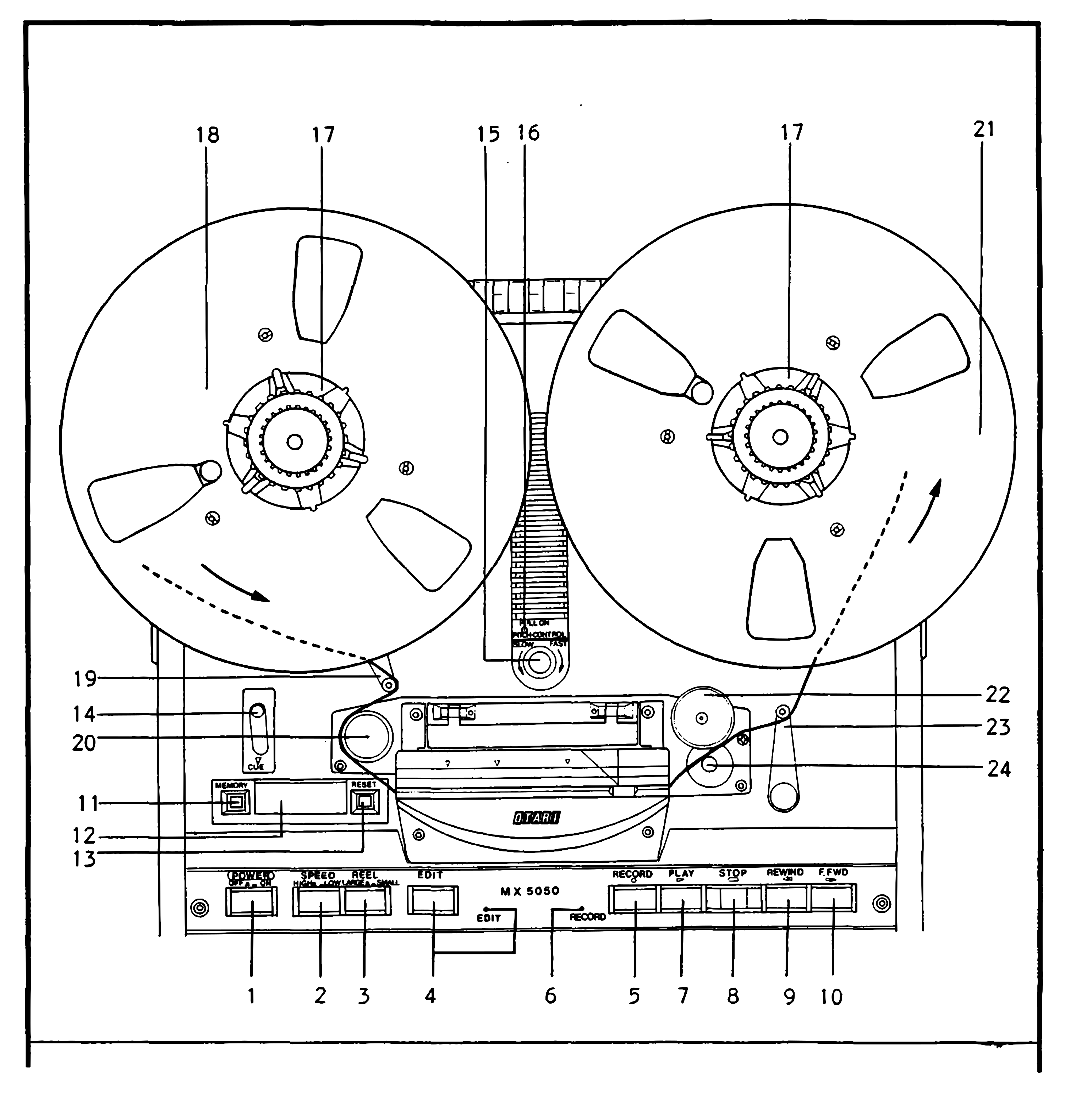 ⤢ zoomFront view of the tape transport with callouts 1 to 24: the reels, reel hold down knobs and tension arms, the PITCH CONTROL knob, the CUE lever, the tape timer with its MEMORY and RESET buttons, the head assembly with its rollers and capstan, and the row of POWER, SPEED, REEL, EDIT and transport-mode pushbuttons.
Table 3-1 Tape Transport Controls and Indicators
| Index No. | Name | Function |
|---|---|---|
| 1 | POWER pushbutton | In the depressed position, power is switch applied to the equipment, and the VU meters illuminate. |
| 2 | HIGH/LOW SPEED pushbutton switch | An alternate-action pushbutton switch used to select operating speed. In the HIGH position for 15 ips (38cm/sec) operation, and in the LOW position for 7 1/2 ips (19cm/sec) operation. |
| 3 | LARGE/SMALL REEL pushbutton switch | An alternate-action pushbutton switch used to select both reel tensions for the reel hubs diameter. In the LARGE position for reels with NAB hubs (4 1/2 in. diameter hubs), and in the SMALL position for reels with EIA hubs (2 1/4 in. diameter hubs). The same size reels should be used on both reel tables. |
| 4 | EDIT pushbutton switch and EDIT indicator (green) | Used to initiate the EDIT mode to aid in cutting out unwanted tape. When the EDIT pushbutton is depressed, the green EDIT indicator illuminates and the power is removed from the take-up reel. Then the PLAY pushbutton is depressed, causing the supply reel to rotate and the tape to be spilled off from the take-up side of the transport. other operations are halted. |
| 5 | RECORD pushbutton switch (momentary) | Used in conjunction with the PLAY pushbutton on the transport and the READY/SAFE pushbutton. With the READY/SAFE pushbuttons on the desired channel depressed, simultaneous pressing of the PLAY and RECORD pushbuttons initiates the RECORD mode and the RECORD indicator on the transport illuminates. In the PLAY mode, when the RECORD pushbutton is depressed, the RECORD mode is entered. (called "Punch in"). In the RECORD mode, when the PLAY pushbutton is pressed, the PLAY mode is entered. (called "Punch out"). "Punch in" and "Punch out" are used for overdubbing in conjunction with the SEL/REP function. |
| 6 | RECORD indicator (red) | Indicates the RECORD mode. |
| Transport | Amplifier | Transport | Amplifier | Recording |
|---|---|---|---|---|
| RECORD indicator | RECORD indicator | |||
| non RECORD mode | SAFE | dark | dark | x |
| non RECORD mode | READY | blinking | blinking | x ready |
| RECORD mode | SAFE | lights | dark | x |
| RECORD mode | READY | lights | lights | O |
| Blinking Indicators means that the amplifier is in the RECORD-READY mode. Recording is being carried out only when the amplifier and transport RECORD indicators remain lit. | ||
| 7 | PLAY pushbutton switch (momentary) | Used to select the PLAY mode, or used in conjunction with the RECORD Pushbutton to perform "Punch in" and "Punch out". Pressing the PLAY pushbutton during the F.FWD or REWIND mode stops the tape motion, and then automatically starts the PLAY mode. |
| Blinking Indicators means that the amplifier is in the RECORD-READY mode. Recording is being carried out only when the amplifier and transport RECORD indicators remain lit. | ||
| 7 | PLAY pushbutton switch (momentary) | Used to select the PLAY mode, or used in conjunction with the RECORD Pushbutton to perform "Punch in" and "Punch out". Pressing the PLAY pushbutton during the F.FWD or REWIND mode stops the tape motion, and then automatically starts the PLAY mode. |
| 8 | STOP pushbutton switch (momentary) | Used to stop the tape motion, cancelling the existing mode of operation. |
| 9 | REWIND pushbutton switch (momentary) | Used to select the REWIND mode to wind the tape from right to left at high speed. This mode can be entered from any mode except EDIT. |
| 10 | F.FWD (FAST FORWARD)pushbutton switch (momentary) | Used to select the F.FWD mode to wind the tape from left to right at high speed. This mode can be entered from any mode except EDIT. |
| 11 | MEMORY pushbutton switch (momentary) | Used to stop the tape at the "00:00:00" position. This mode can be entered from any mode except both EDIT and RECORD. |
| 12 | TAPE TIMER (7-segment LED) | A 6-digit TIMER used to locate or log Program material on the tape. The first two digits indicate sign and hour; the second two digits indicate minutes; and the last two digits indicate seconds. |
| 13 | RESET pushbutton switch | Used to reset the figure of the TAPE TIMER to "00:00:00". |
| 14 | CUE lever | Used to carry out audio monitoring in the F.FWD and REWIND modes. To lock the lever, shift the lever to the full down position. |
| 15 | PITCH CONTROL | Used to control tape speed. The capstan speed can be controlled within ±7% of nominal speed when the PITCH CONTROL knob is pulled out. (variable mode) Turning clockwise causes the capstan speed to increase and turning counterclockwise, causes the capstan speed to decrease. PITCH CONTROL functions in both the RECORD and PLAY modes. |
| 16 | PITCH CONTROL indicator (red) | Illuminates when the PITCH CONTROL knob is pulled out. (In variable mode). |
| 17 | NAB Hub Reel Hold Down Knobs | Used to attach EIA or NAB hub reels to the reel table. (Refer to 3-2-(1)) |
| 18 | Supply Reel | Supplies tape for reproduction or recording. |
| 19 | Tension Arm | Damps tape tension fluctuations. |
| 20 | Impedance roller | Reduces wow and flutter. |
| 21 | Take-up reel | Takes up tape. |
| 22 | Pinch roller | Correctly transmits the tape with the capstan. |
| 23 | Tension Arm with Safety switch | Damps tape tension fluctuations. When tape is exhausted, supply and take-up reel rotation is automatically stopped by the safety switch attached to the tension arm. |
| 24 | Capstan shaft | Keeps the tape .speed constant in the reproduce and record modes. |
Table 3-2 shows the location and function of each control and indicator on the Record/Reproduce electronics control panel.
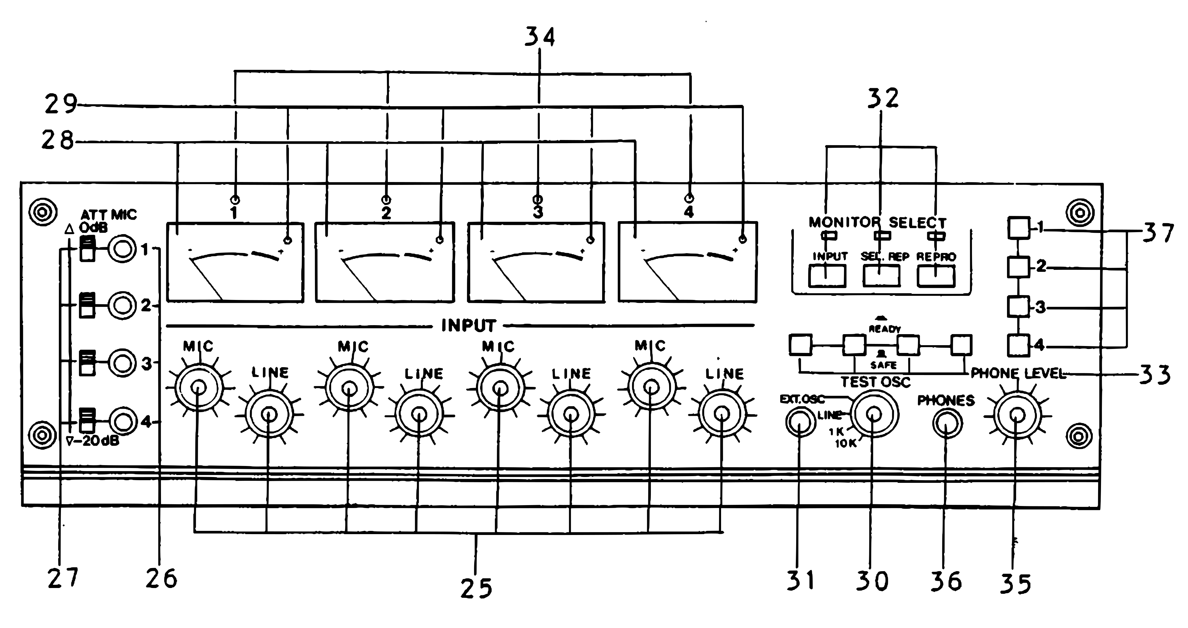 ⤢ zoomThe record/reproduce electronics panel with callouts 25 to 37: four VU meters with their PEAK and RECORD indicators, the MIC ATT switches and MIC jacks, a MIC and a LINE INPUT level control per channel, the MONITOR SELECT pushbuttons, the READY/SAFE pushbuttons, the TEST OSC switch and EXT OSC jack, the PHONES jack, the PHONE LEVEL control and the four PHONE SELECT pushbuttons.
Table 3-2 Record/Reproduce Electronics Controls and Indicators
| Index No. | Name | Function |
|---|---|---|
| 25 | MIC/LINE INPUT level controls | Used to control recording levels of microphone and line of the associated channel. Both levels can be mixed. |
| 26 | MIC INPUT jacks | Standard single-conductor phone jack for unbalanced microphone input (-70 dBm). Applicable microphone impedance is 150 ohm to 1 kohm. |
| 27 | MIC Attenuator switches | Used to select the microphone input Level. In upper position, input level is -70 dBm (0 dB). In lower position, input level is -50 dBm (-20 dB). |
| 28 | VU meters | Indicate the record and playback level of the associated channel depending on the mode of operation and position of the MONITOR SELECT switches. (Index No. 32 in this table.) The meters illuminate when the power is turned on. |
| 29 | PEAK indicators | Indicate signal peaks. When the input or output signal exceeds AMPEX operating level (185 nWb/m) by 15 dB (1040 nWb/m), the PEAK indicator lights. Trigger level can be adjusted. Factory set level is 12.4 dB (NAB) of 10.2 dB (IEC) over 0 VU. |
| 30 | TEST OSCillator switch | Used to select the LINE INPUT signal. The line position should be normally set to get the audio signal from the line input connector for recording. The "1K" or "10K" position is set to feed a tone of 1KHz or 10KHz to the line input circuit for CUE tone recording or electrical adjustment. The EXT OSC position is set to feed the tone from the EXT OSC jack to the line input circuit. |
| 31 | EXT OSCillator jack | Used to feed signal from external audio oscillator. Standard single-conductor phone jack. Input Impedance 10 kohm Minimum input : -18 dBm |
| 32 | MONITOR SELECT pushbutton switches and Indicator (green) | Used to select the output signals fed to the LINE OUTPUT connectors and the PHONE jack for monitoring. The signals are indicated on the VU meters of the associated channels. By pressing the INPUT pushbutton, the INPUT Indicator lights up and the input signal is from the LINE INPUT connectors and/or MIC jacks are fed to the output of all channels. By pressing the SEL/REP (selective reproduction) pushbutton, the SEL/REP indicator lights up and the signals via the record head are fed to the output of all channels. Entering the RECORD mode, the monitor program on both SEL/REP and READY (Index No. y~ in this table) selected channel(s) are automatically switched from SEL/REP to INPUT. (The SEL/REP indicator remains lit.) This function is for "Punch in" and "Punch out". By pressing the REPRO pushbutton, the REPRO indicator lights up and the signals via the reproduce head are fed to the output of all channels. |
| 33 | READY/SAFE pushbutton switches | Alternate-action pushbutton switch used to select channels for recording in conjunction with the PLAY and RECORD pushbuttons on the transport. Selecting the "IN" READY position, the RECORD indicators illuminate or blink and the RECORD mode of associated channels can be entered or ready. Selecting the "OUT" SAFE position, the RECORD indicators turn off and activation of associated channels RECORD mode are cancelled. (Index No.5.6.7 in this table.) |
| 34 | RECORD indicators (red) | Indicate activation of associated channel RECORD mode. |
| 35 | PHONE LEVEL control | Used to control all channel PHONE LEVELs with interlocking. |
| 36 | PHONES jack | Standard two-conductor phone jack available for both stereo and monaural headphones. Used to monitor the output signal selected by the MONITOR SELECT pushbutton switches. Load impedance: 8 ohm or greater Output level : -19 dBm with an 8 ohm load |
| 37 | PHONE SELECT pushbutton switches | Alternate-action pushbutton switches used to select the channel to be monitored. All channels can be mixed. |
3-2 OPERATING INFORMATION↑ TOP
3-2-(1) USING THE REEL HOLD DOWN KNOBS↑ TOP
The NAB hub reel hold down knobs shown in Figure 3-1 are used to attach the NAB hub and EIA hub tape reel on to the reel table, proceed as follows:
For the EIA hub (2 1/4 inch diameter hub) tape reel;
(1) Remove the NAB reel hold down knob from the reel table by turning the inner knob counterclockwise and pulling it.
(2) Place the EIA hub tape reel onto the reel table so that the three slots of the tape reel correspond to the three notches of the reel shaft.
(3) Attach the reel hold down knob onto the reel to fix the tape reel and turn the inner knob clockwise to lock the reel hold down knob to the reel shaft.
For the NAB hub (4 1/2 inch diameter hub) tape reel;
(1) Place the reel hold down knob on the reel table and turn the inner knob clockwise to lock the reel hold down knob to the reel shaft.
(2) Place the NAB hub tape reel onto the reel table so that the three slots of the tape reel correspond to the three notches of the base of the reel hold down knob.
Pulling and turn the outer knob 60° to fix the tape reel.
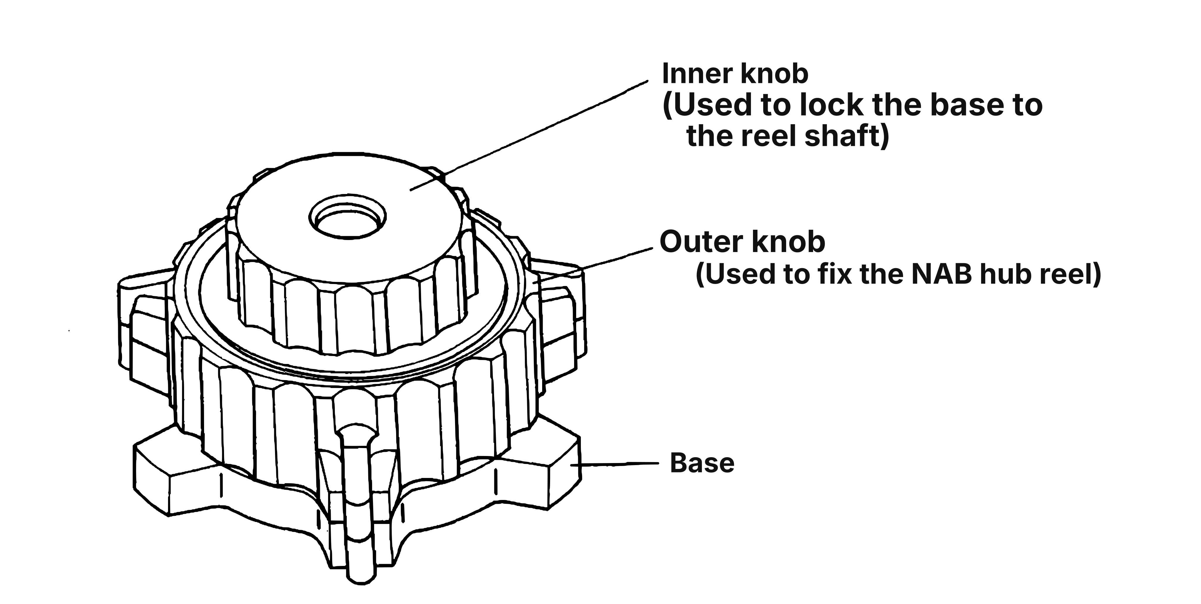 ⤢ zoomThe NAB hub reel hold down knob, labelled Inner knob (used to lock the base to the reel shaft), Outer knob (used to fix the NAB hub reel) and Base.
Figure 3-1 Reel Hold Down Knob
3-2-(2) PRE-OPERATING PROCEDURE↑ TOP
After the equipment has been installed as described in Section 2 of this manual and the operator has become familiar with all the operating controls and indicators described in Tables 3-1 and 3-2, prepare the recorder for operation as follows.
(1) Press the POWER switch to the "IN" on position. The VU meters light up and the Tape Timer illuminate.
(2) Place a reel of tape on the supply (left-hand) reel table as described in Section 3-2-(1). If metal reels are used, use reel-adjusting discs (shims) between the tape reels and the reel tables. Note that the reel must turn counterclockwise as tape is pulled off the reel.
(3) (3) Place the same size empty reel on the take-up (right-hand) reel table as described in Section 3-2-(1). The same size reels should be used on both reel tables.
(4) Thread the tape as shown in Figure3-2 and place the end of the tape in the slot of the empty reel, and rotate the reel for several times with holding the tape end and removing slack of the tape.
(5) Set the HIGH/LOW SPPED switch to the desired tape speed.
(6) Set the LARGE/SMALL REEL switch to correspond to the size of the reel hub diameter being used. Place the switch to the "OUT" LARGE position for NAB hubs (4 1/2 inch diameter) or to the "IN" SMALL position for EIA hubs (2 1/4 inch diameter).
(7) If desired, connect a headset or monitor speaker/ amplifier to the PHONES jack.
(8)
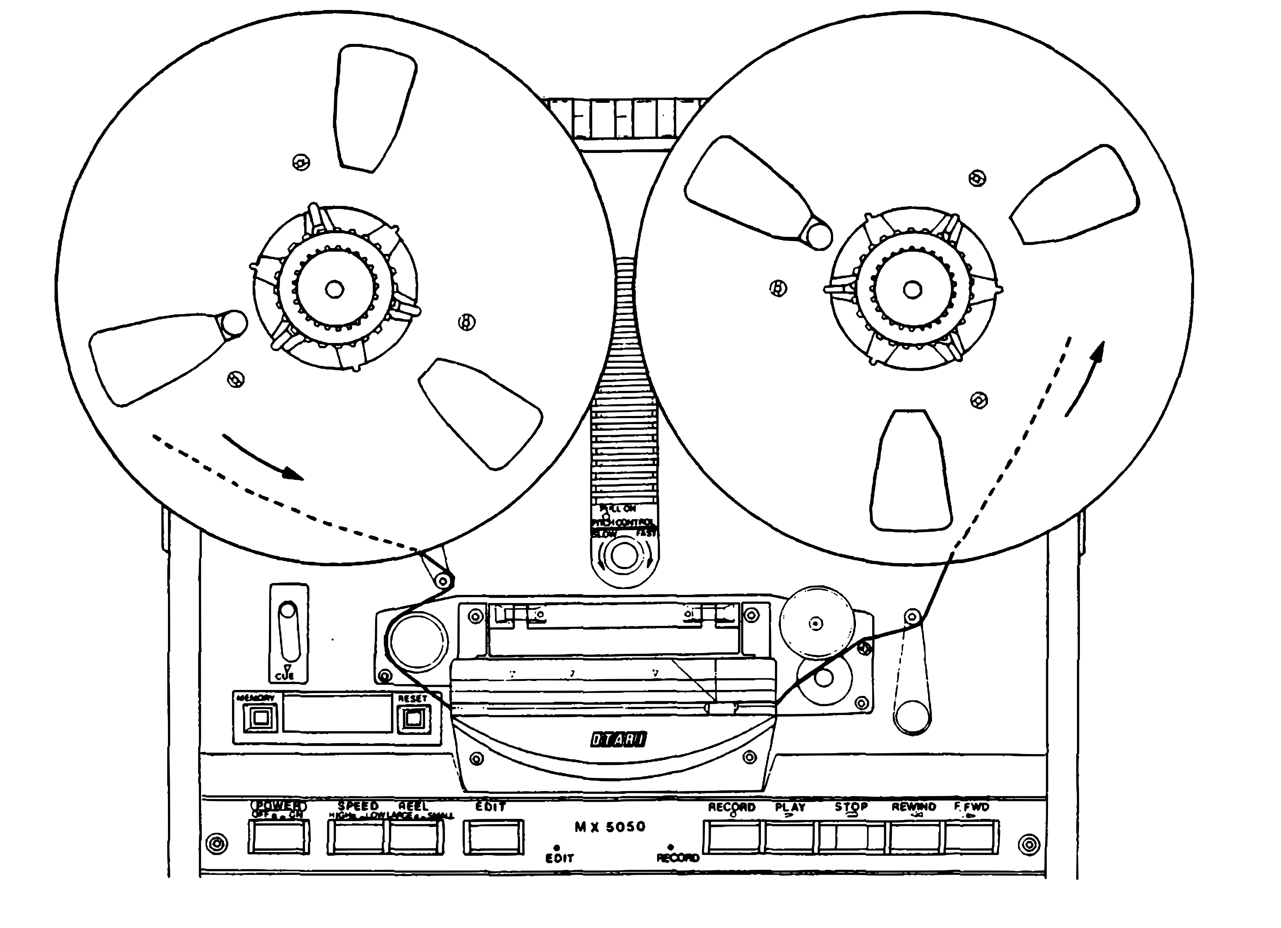 ⤢ zoomThe tape path on the transport, with arrows from the supply reel round the left tension arm and impedance roller, across the heads, between capstan and pinch roller, and round the right tension arm onto the take-up reel.
Figure 3-2 Tape Threading
3-2-(3) REPRODUCTION↑ TOP
To reproduce, proceed as follows:
(1) Perform all steps in the pre-operating procedure.
(2) Set the all channel READY/SAFE pushbutton switches to the "OUT" SAFE position to avoid mis-erasing of the recorded tape program.
(3) Press the "REPRO" of MONITOR SELECT pushbutton switches to select the tape monitoring.
(4) Depress the PLAY pushbutton to start the transport.
(5) To stop the reproduction of the tape program, depress the STOP pushbutton at a desired position.
3-2-(4) NORMAL RECORDING↑ TOP
To record normally, proceed as follows:
(1) Perform all steps in the pre-operating procedure.
(2) Set the READY/SAFE pushbutton switch(es) of the channel(s) desired to record to the "IN" READY position. The red record indicators of the transport and the related channels of the record/reproduce electronics start blinking to indicate the RECORD-READY condition.
(3) Depress the "INPUT" of the MONITOR SELECT pushbutton switches to select the signal from the LINE INPUT connector and/or the MIC INPUT jack.
NOTE:
Set the MIC ATT switch on the record/reproduce electronics to either the "0 dB" or "-20 dB" position in accordance with the microphone output level being used. The microphone and the line signal can be mixed.
(4) Adjust the LINE and/or MIC INPUT level control(s) of related channel(s)
selected to record so that the VU meter(s) of that channel (s) indicates 0
VU at the most audio peaks.
Note that the peak indicator located in the each VU meter blinks
occasionally at this point.
(5) Depress the RESET pushbutton switch of the tape timer to set "00:00:00".
(6) Depress the PLAY and RECORD pushbuttons of the transport simultaneously to
start recording.
The red RECORD indicators of the selected channel(s) and transport light up
continuously to indicate the RECORD mode.
(7) While recording, the input signal(s) of each channel can be compared with the signal reproduced on each channel by depressing "REPRO" of the MONITOR SELECT pushbutton switches.
(8) In the RECORD mode, depress only the PLAY pushbutton on the transport to
enter directly into the PLAY mode without stopping the tape motion, called
"punch out".
The RECORD indicator(s) of the channel(s) and the transport changes to blinking
instead of lighting up continuously to indicate the RECORD-READY
condition.
(9) In the PLAY mode, of course the RECORD-READY condition, depress only the
RECORD pushbutton on the transport to enter directly into the RECORD mode
without stopping the tape motion, called "punch in".
The RECORD indicators light up continuously to indicate the RECORD mode.
(10) To stop tape motion, depress the STOP pushbutton on the transport.
(11) To find the exact "00:00:00" position on the tape, press the MEMORY pushbutton several times.
3-2-(5) RECORDING WITH SELECTIVE REPRODUCTION↑ TOP
The selective reproduction function causes the reproduced program to be monitored from the record head rather than from the reproduce head.
This enables a recording to be made on another channel synchronized (in phase) with the channel being reproduced.
To record with selective reproduction, proceed as follows:
(1) Perform all steps in the pre-operating procedure.
(2) Perform all steps in the normal recording procedure for the channel(s) to be prerecorded.
(3) Rewind the tape to the point where selective reproduction is to start.
(4) Set the READY/SAFE pushbutton switch(es) of the channel(s) selected for recording to the 1llNll READY position.
(5) Press the “INPUT” of the MODE SELECT pushbutton switches.
(6) Adjust the LINE and/or MIC INPUT level control(s) so that the VU meter indicates
0 VU at the most audio peaks.
Note that the peak Indicator located in the each channel VU meter blinks
occasionally at this point.
(7) Then press the “SEL/REP” of the MODE SELECT pushbutton switches.
(8) Press the PLAY pushbutton to start tape motion.
At the point where overdub is desired, press the RECORD pushbutton to start
recording on the selected channel(s).
The monitor program on the channel(s) not selected the READY is reproduced by
the record head, synchronized with the recording program in phase. (SEL/REP)
The monitor program on the channel(s) selected the READY is the recording
signal. (INPUT)
(9) When recording is complete, depress the STOP pushbutton to stop tape motion and
deactivate the RECORD mode, or depress the PLAY pushbutton for punch out
operation.
Note: The pitch control is available to finely adjust the tape speed to one
track (pre-recorded track) with another track for overdubbing which can be used
in both the Record and Reproduce modes.
3-2-(6) FAST WINDING↑ TOP
For fast-winding operations, and for editing or cueing, press the F.FWD or REWIND pushbutton switch as appropriate.
These pushbuttons can be pressed alternately without pressing the STOP pushbutton between fast-winding operations.
These modes may be entered into from any other mode except the EDIT mode.
Pressing the PLAY pushbutton during a fast-winding mode causes the tape to automatically come to a stop and then enter into the PLAY mode.
In a fast-winding mode, the tape lifters are automatically actuated and lift the tape away from the heads.
To monitor the tape in a fast-winding mode, the position of the tape lifters can be varied by operation of the CUE lever.
Thus the distance of the tape from the heads may be varied to control the signal level from the tape.
3-2-(7) EDITING AND SPLICING TAPE↑ TOP
For editing and splicing operations, the CUE lever can be used in fast-winding modes to quickly locate the desired program material.
In addition, there is an EDIT mode of operation, used as follows:
Depressing the EDIT pushbutton while in the PLAY mode removes power from the take-up reel and causes the tape to be spilled off on the take-up side of the transport.
This mode is used to facilitate cutting out unwanted tape.
The EDIT mode can also be entered into from the STOP mode by pressing the PLAY pushbutton after the EDIT pushbutton is depressed.
The tape-splicing block (Figure 3-3) mounted on the head cover can be used to hold the tape for ease in cutting the tape with a single edged razor blade and applying splicing tape.
Use 7/32-inch width splicing tape (3M Co., No. 41 l, and never use cellophane tape.
The tape splicing block has the following features:
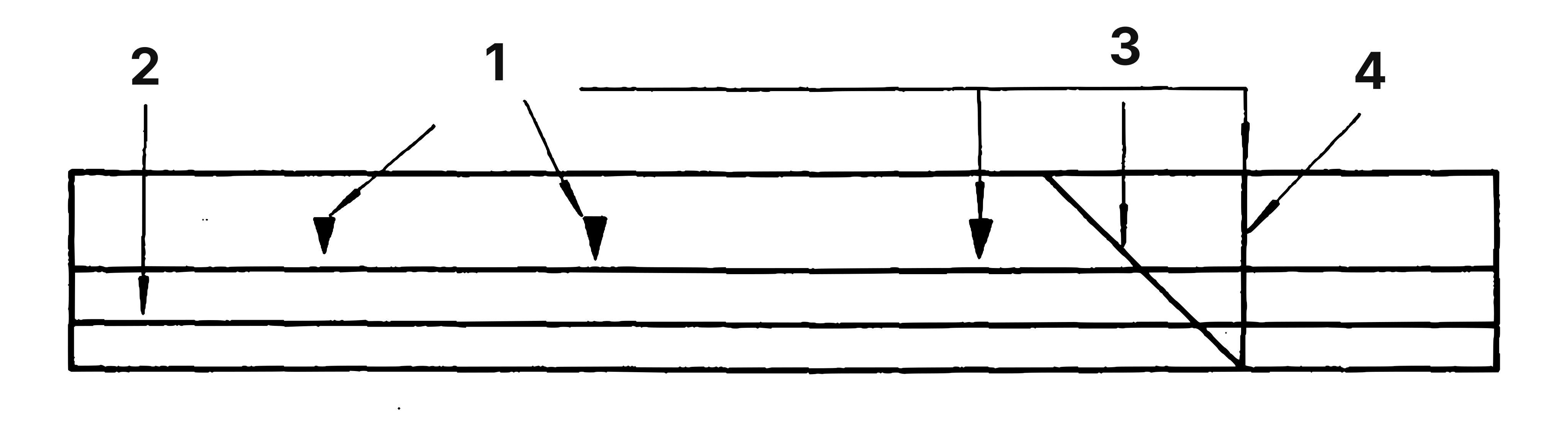 ⤢ zoomThe tape-splicing block seen from above, a long channelled bar with callout 1 on its head-stack indicator marks, 2 on the tape-guide channel, 3 on the 45° diagonal cutting slot and 4 on the 90° vertical cutting slot.
Figure 3-3 Tape Splicing Block
| 1 | Head-stack indicator marks: | Indicates location of the individual head stack. |
| 2 | Tape-guide channel: | Holds the tape for ease of cutting and splicing. |
| 3 | 45° cutting guide: | Used to guide tape cutter for a diagonal cut for splicing |
| 4 | 90° cutting guide: | Used to guide tape cutter for a vertical cut. |
To determine the exact location of the point where the tape should be cut during editing, note that the distance from the right or left hand calibration mark to the 90°cutting guide is the same as the distance from the right or left hand tape guide assembly to the center of the reproduce head.