MX-5050BII Instruction Manual — Digital Edition · Part 2 · scan pages 20-28
Installation
This section of the manual provides information on unpacking and inspection, location and environment, and power and signal connections.
2.1 UNPACKING AND INSPECTION↑ TOP
The MX-5050BII Series system is shipped from the factory in a single cardboard packing case. Upon receipt, examine the case for any signs of damage. Unpack the equipment and inspect for any signs of damage. Use great care when unpacking the equipment and removing packing materials to prevent damage to critical components such as the capstan, head assembly, and tension arms.
Referring to the lists in Secs. 1.2 and 1.3 (as applicable), verify that all items have been received. Report any shortage or damage to the carrier and your local Otari dealer. Save the packing case for possible reshipment. Other packaging may cause damage during transportation and will void the warranty.
Please refer to the illustration which is attached to flap of the packing box regarding the repacking method.
2.2 LOCATION AND ENVIRONMENT↑ TOP
The area chosen for operation should be adequately ventilated and dust free. Since recording is by an electromagnetic process, it is possible that strong electromagnetic fields may affect the system adversely. Common sources of interference are fluctuating loads on nearby high-voltage lines, heavy duty transformers, and transmitting equipment.
It is recommended that the equipment be used in an environment where the surrounding temperature does not exceed limits of 40° to 104°F (5° to 40°C), with the relative humidity between 20 and 80%. Allow at least a 4 inch (10 cm) clearance behind the rear-panel ventilation grill.
2.3 DIMENSIONS↑ TOP
Equipment dimensions of the MX-5050BII Series are shown in Fig. 2-1.
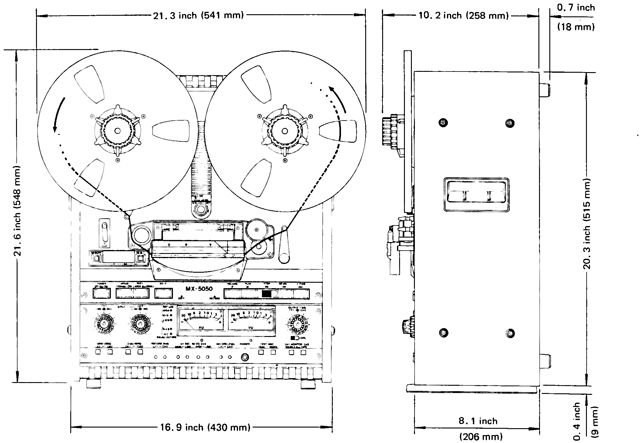 ⤢ zoomTwo line-art views of the MX-5050BII cabinet — front, with its reels, and side — with dimension call-outs in inches and millimeters.
Fig. 2-1 Equipment Dimensions
2.4 STANDARD SWITCH POSITION ON SHIPMENT↑ TOP
Either the NAB standard or the IEC standard of equalization, recording level, etc. may be used with the Otari MX-5050BII series. These units have been provided with a slide switch on the back panel which selects one of these two standards; to change standards, merely slide the switch to the desired position.
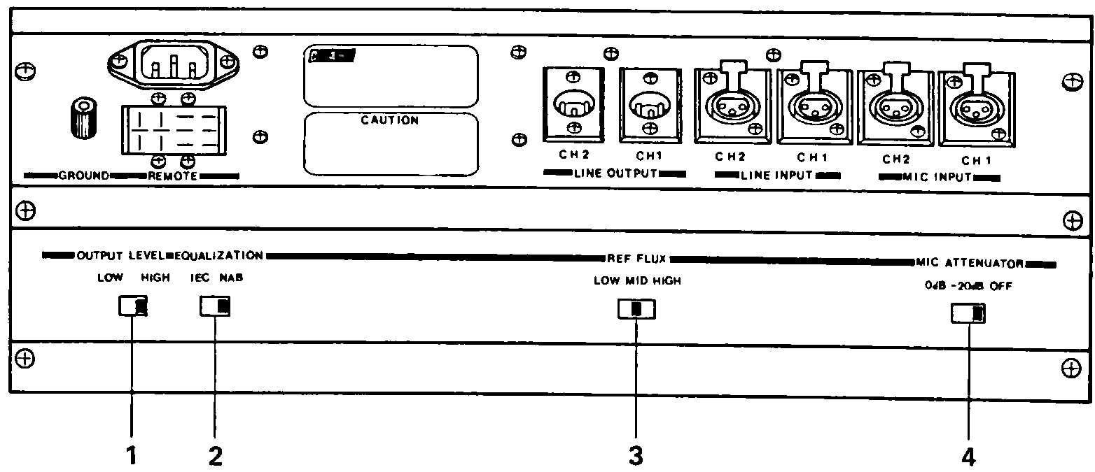 ⤢ zoomLine drawing of the MX-5050BII rear panel with its switch row, marked for the NAB standard switch positions, with four numbered call-outs.
Fig. 2-2(a) Standard Switch Position on Shipment (NAB)
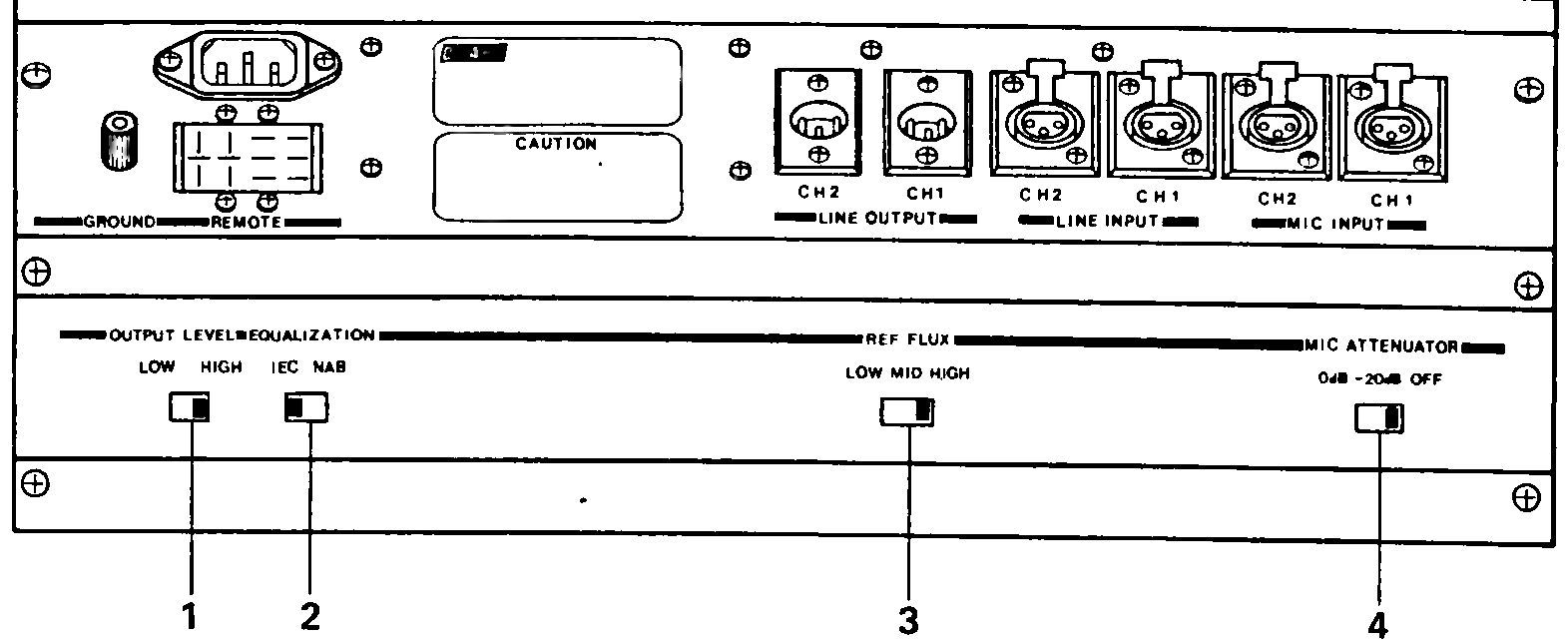 ⤢ zoomThe same rear-panel switch row, marked for the IEC standard switch positions instead.
Fig. 2-2(b) Standard Switch Position on Shipment (IEC)
Table 2-1 Standard Switch Position on Shipment
| Switch | Ref. No. | Type | |
|---|---|---|---|
| NAB | IEC | ||
| OUTPUT LEVEL | 1 | HIGH | HIGH |
| EQUALIZER | 2 | NAB | IEC |
| RECORD LEVEL | 3 | M | H |
| MIC. ATT | 4 | OFF | OFF |
2.5 POWER AND SIGNAL CONNECTION↑ TOP
All power and signal connections are made on the connector panel of the MX-5050BII. Table 2-2 shows the function of each connector and component on the rear panel.
Table 2-2 Rear Connector Panel
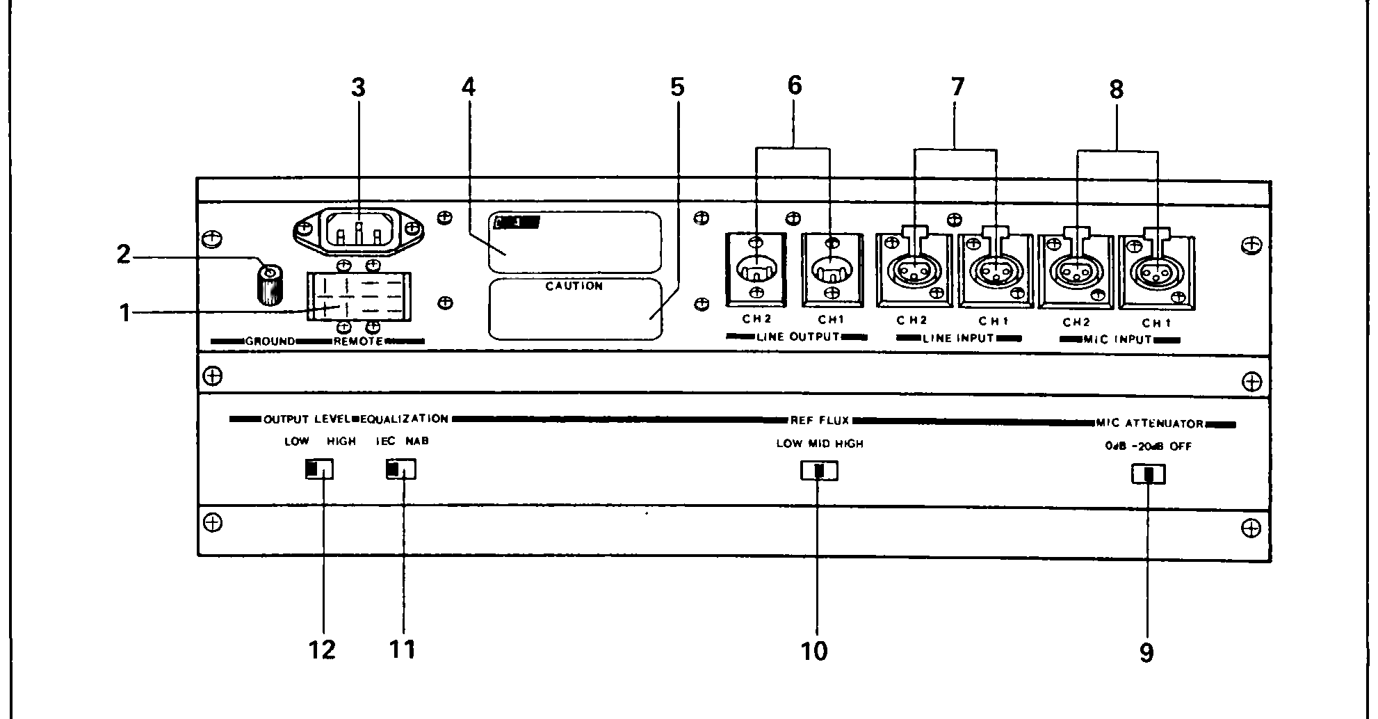 ⤢ zoomLine drawing of the MX-5050BII rear connector panel, with its twelve numbered call-outs (1 through 12) matching the Index No. column of Table 2-2.
| Index No. | Name | Function |
|---|---|---|
| 1 | REMOTE Control Connector | Remote control connector for use with the optional remote control unit to control the record, play, stop, rewind, and fast forward modes. |
| 2 | GROUND Terminal | Auxiliary ground connection for use with equipment not connected to a common AC ground. |
| 3 | AC Power Connector | Three-contacts socket for connection to AC power and ground. |
| 4 | Label | Indicates model number, production lot number (serial number), power requirement, and place of manufacture. |
| 5 | CAUTION Label | Precautions for preventing fire and shock. |
| 6 | LINE OUTPUT Connector | Male XLR-type connector. Active balanced output (Floating type). Source impedance: 5 ohms Load impedance: 600 ohms or greater. Level: +4 dBm or -10 dBm at 0 VU switchable by the OUTPUT LEVEL switch. |
| 7 | LINE INPUT Connector | Female XLR-type connector. Active balanced input (Floating type). Input impedance: 10 k ohms Minimum input : -15 dBm Maximum input before clipping: +30 dBm Optional transformer balanced input. Input impedance: 10 k ohms Minimum input : -15 dBm Maximum input before clipping: +30 dBm |
| 8 | MICROPHONE Input Connector | Female XLR-type connector. Active balanced input (Floating type). Applicable microphone impedance: 150-10 k ohms. Minimum input: -70 dBm or -50 dBm switchable by means of the MIC ATTENUATOR switch. |
| 9 | MICROPHONE ATTENUATOR Switch | Used to adjust the sensitivity of the microphone amplifier in accordance with the microphone's input level. |
| ATT | Minimum Input (Sensitivity) |
|---|---|
| 0 dB | -70 dBm |
| -20dB | -50 dBm |
| OFF | Shorted to the ground |
| 9 | (Continued) | When a microphone is not used, this switch should be placed in the "OFF" position to avoid noise from the microphone amplifier being placed on the tape. |
| 10 | RECORD LEVEL Selector Switch | This switch is used for setting the recording level: "High", "Medium", and "Low". Located on the Amplifier front panel are 3 LED Record Level Selector Indicator displays which indicate the position of the switch. (185/250/320) |
| Position | Flux | Relative Level | Test Tape | Recording tape to be used |
|---|---|---|---|---|
| Low | 185 nWb/m* | 0 dB | Ampex Operat- | Scotch 177 Ampex 641 |
| Medium | 250 nWb/m* | +2.6 dB | MRL NAB Reference Flux | Scotch 206, 207, 226, 250 Ampex 406, 407, 456 |
| High | 320 nWb/m** | +3.8 dB | BASF or MRL IEC Standard | IEC Equalization |
* Short circuit flux ** Open circuit flux
RECORD LEVELS FOR DIN STEREO VERSION DIFFER FROM ABOVE. REFER TO PAGE 1-9.
| 11 | EQUALIZER Selector Switch | The two-position EQUALIZER selector switch is used to select either LEC or NAB equalization. The equalizer of this unit has five settings. These have already been adjusted before shipment. These settings may be changed, but it is necessary to tune them finely. |
1 NAB 15 ips (3180 + 50 µsec)
2 NAB 7.5 ips (3180 + 50 µsec)
3 IEC 15 ips (∞ + 35 µsec)
4 IEC 7.5 ips (∞ + 70 µsec)
5 Both NAB and IEC 3.75 ips (3180 + 90 µsec)
| 11 | (Continued) | Located on the amplifier front panel are 2 LED EQ Selection Indicator displays which indicate the position of this switch (NAB or IEC). |
| 12 | LINE OUTPUT LEVEL Selector Switch | A two-position output level switch used to select either the +4 dBm or -10 dBm output standard reference level (SRL). |
2.5.1 AC POWER CONNECTION↑ TOP
The MX-5050BII Series is factory set to operate at the line voltage and frequency indicated on the packing case and on the rear connector panel of the equipment. AC power is connected by means of a three-wire power cable which also provides a common ground connection.
If a change of line voltage and/or frequency is desired to accommodate different power requirements, please refer to followings or contact your nearest Otari dealer.
VOLTAGE CONVERSION PROCEDURE:
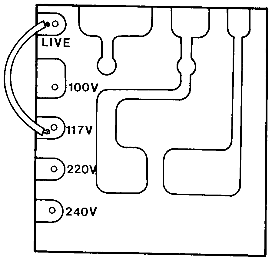
Remove the back panel (refer to Fig. 5-1 for access information). From the top of the unit near the supply reel motor, please note the small P.C.B. assembly with the various voltage listings, i.e. 100/117/220/240 (refer to Fig. 2-3). Unsolder the wire from its present setting and resolder it to the desired position. Replace the back panel.
 ⤢ zoomLine-art drawing of a small PCB terminal strip with labelled voltage-selection pins and a curved arrow showing the jumper wire's factory position.
Fig. 2-3 Voltage Selection Terminal
2.5.2 SIGNAL CONNECTIONS↑ TOP
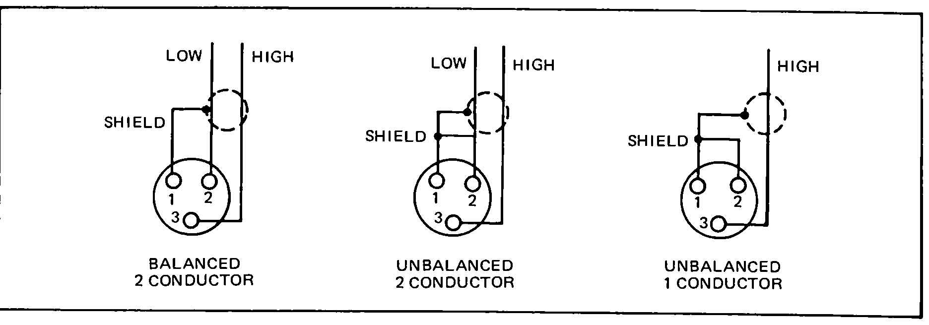
The microphone input (female), line input (female) and line output (male) connectors are XLR-type connectors. To wire the mating plugs, refer to Fig. 2-4 and proceed as follows.
LINE AND MIC INPUT CONNECTOR WIRING:
For balanced inputs, wire the male XLR-connector as follows:
(1) Connect the signal leads of a two-conductor shielded cable to pin 3 (high) and pin 2 (low) of the connector. (2) Connect the cable shield to pin 1.
For unbalanced inputs using two-conductor shielded cable, wire the male XLR-connector as follows:
(1) Connect the signal leads of a cable to pin 3 (high) and pin 2 (low) of the connector. (2) Connect the cable shield to pin 1 of the connector. (3) Connect a jumper from pin 1 to pin 2 of the connector.
For unbalanced inputs using single-conductor shielded cable, wire the male XLR-connector as follows:
(1) Connect the center conductor of the single-conductor shielded cable to pin 3 of the connector. (2) Connect the cable shield to pins 1 and 2.
 ⤢ zoomBoxed line-art panel showing three side-by-side XLR pin-wiring diagrams for balanced and unbalanced connections, each with pins 1 through 3 labelled.
Fig. 2-4 Input/Output Assembly Connector Wiring
LINE OUTPUT CONNECTOR WIRING:
For balanced outputs, wire the female XLR-connector as follows: (1) Connect the signal leads of a two-conductor shielded cable to pin 3 (high) and pin 2 (low) of the connector. (2) Connect the cable shield to pin 1.
For unbalanced outputs using two-conductor shielded cable, wire the female XLR-connector as follows: (1) Connect the signal leads of the cable to pin 3 (high) and pin 2 (low) of the connector. (2) Connect the cable shield to pin 1 of the connector. (3) Connect a jumper from pin 1 to pin 2 of the connector.
For unbalanced outputs using single-conductor shielded cable, wire the female XLR-type connector as follows: (1) Connect the center conductor cable to pin 3 of the connector. (2) Connect the cable shield to pin 2 of the connector. (3) Connect a jumper between pins 1 and 2 of the connector.
UNBALANCED CONNECTION:
MX-5050BII series have active balanced input and output circuits. However both balanced and unbalanced connections will operate with no problems.
TRANSFORMER BALANCE CIRCUITS:
If you prefer "transformer type balanced circuits" optional accessories ZA-53T (input) and ZA-53S (output) are available. Contact your nearest OTARI dealer or OTARI for further details.