MX-5050 MKIV-2 and BIII-2 Operation and Maintenance Manual — Digital Edition · Part 1 · PDF pages 14-17
Introduction
This Section includes a general description of the features of the MX-5050 series tape recorders and information on the structure of this manual.
| 1.1 | MX-5050 Series | 1-2 |
| 1.2 | Using This Manual | 1-3 |
| 1.2.1 | Organization | 1-3 |
| 1.2.2 | Conventions within this manual | 1-4 |
1.1 The New MX-5050 Series↑ TOP
The features of the MX-5050 Series tape recorders are described below.
The new MX-5050 Series is divided into the following models:
| MX-5050 BIII-F | Full Track, 1/4" Track Width |
| MX-5050 BIII-2 | 2 Channel, NAB 1/4" Track Width |
| MX-5050 BIII-2E | 2 Channel, DIN 1/4" Track Width |
| MX-5050 BQIII | 4 Channel, 1/4" Track Width |
| MX-5050 MKIV2 | 2 Channel, NAB 1/4" Track Width |
| MX-5050 MKIV2E | 2 Channel, DIN 1/4" Track Width |
| MX-5050 MKIV4 | 4 Channel, 1/2" Track Width |
| MX-5050 MKIV8 | 8 Channel, 1/2" Track Width |
This manual describes the MX-5050 MKIV-2, 2E, BIII-F, BIII-2 and BIII-2E models.
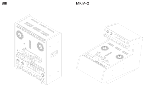 ⤢ zoomFigure 1-1 Exterior Appearance: two three-quarter-view line drawings of the recorder — the BIII on the left, an upright deck with its transport mounted on a vertical front panel and a recessed carrying handle in the side cheek, and the MKIV-2 on the right, a sloped-front console with a raised meter-and-knob amplifier panel standing at the rear — each labeled with its model name above the drawing.
Features of the MX-5050 Series
In addition to the usual tape recorder functions, the MX-5050 series has various additional features. All MX-5050 series tape recorders have the OTARI Standard Parallel I/O connector which allows for post production editing work with a synchronizer using time code. The tape timers include a Mini Locator for more advanced locator functions.
In addition to these functions, these machines also have the following features: Sel-Rep (Selective Reproduce), Edit mode function which permits tape spilling, CUE monitoring which enables monitoring the tape in F.FWD or RWD mode, Standby function for easy multi-channel recording, and Variable Pitch Control function (±20%).
1.2 Using This Manual↑ TOP
1.2.1 Organization↑ TOP
This manual is divided into ten sections as follows.
Section 1 Introduction
This section describes the features of the MX-5050 series tape recorders and the structure of this manual.
Section 2 Installation
This section describes the procedures for unpacking and hooking up the machine. This section also includes the DIP switch presettings.
Section 3 Controls and Indicators
This section describes the name and function of each control. The connector pin assignments are also included.
Section 4 Operation
This section explains each mode of the machine and the basic procedures for reproducing and recording a tape.
Section 5 Maintenance
This section describes procedures for daily maintenance.
Section 6 Transport Adjustment and Parts Replacement
This section describes the adjustment procedures for transport mechanisms and replacement procedures.
Section 7 Audio Alignment
This section describes the electrical adjustment of the Reproduce and Record circuits.
Section 8 Specifications
This section of the manual contains the operating specifications for MX-5050 series tape recorders.
Section 9 Exploded Views and Parts Lists
This section of the manual contains assembly drawings of the machine "exploded" to show internal parts and hardware, and the order of assembly. Each exploded view is keyed to an accompanying parts list showing Otari part numbers and descriptions for all mechanical components.
Appendix A Block Diagrams
This appendix includes block diagrams of the MX-5050 and level diagrams of the circuitry.
Appendix B Troubleshooting
This section describes some typical problems which may occur during operations, their possible causes and how to handle them.
1.2.2 Conventions within this manual↑ TOP
PCB Assemblies: The term PCB Assembly is used in this manual to refer to a printed circuit board which has components (resistors, connectors, etc.) mounted on it. The term PCB or Printed Circuit Board, when used alone refers to the "bare" printed circuit board without components. The term PCB is rarely used outside of the electrical and mechanical parts lists. When a PCB Assembly is referred to in the text, the name or function of that PCB Assembly will usually be given in ALL CAPITAL letters.
Type conventions
ALL UPPER CASE - Generally, this manual uses all upper case type to describe a switch or control when that item is similarly labeled on the machine (e.g., the PLAY button).
First Letter - Where a switch or button is not Upper Case labeled, or the reference is less clear, only the first letter of the item is capitalized (e.g., the Cue Wheel near the CUE button). Machine status or operating modes are described with an upper case first letter (e.g., you press the PLAY button to place the machine in Play mode).
( ), [ ] - Normal parentheses ( ) are used for examples and parenthetic comments. Square brackets [ ] are used to refer to certain illustrations. When used in text, the square brackets are either references to the same figure as noted in that sub-section (e.g., [3], meaning the part labeled "3" in the figure noted) or are preceded by the figure number (e.g., Fig. 2-1, [3], meaning "3" in Figure 2-1).