MX-5050 BII and MKIII-2 Alignment Procedures — Digital Edition · Part 2 · scan pages 4-8
Speed Calibration and Capstan Servo Offset Adjustment
2.0 SPEED CALIBRATION AND CAPSTAN SERVO OFFSET ADJUSTMENT↑ TOP
2.1 MX-5050 BII SPEED CALIBRATION↑ TOP
With the Power to the machine turned OFF:
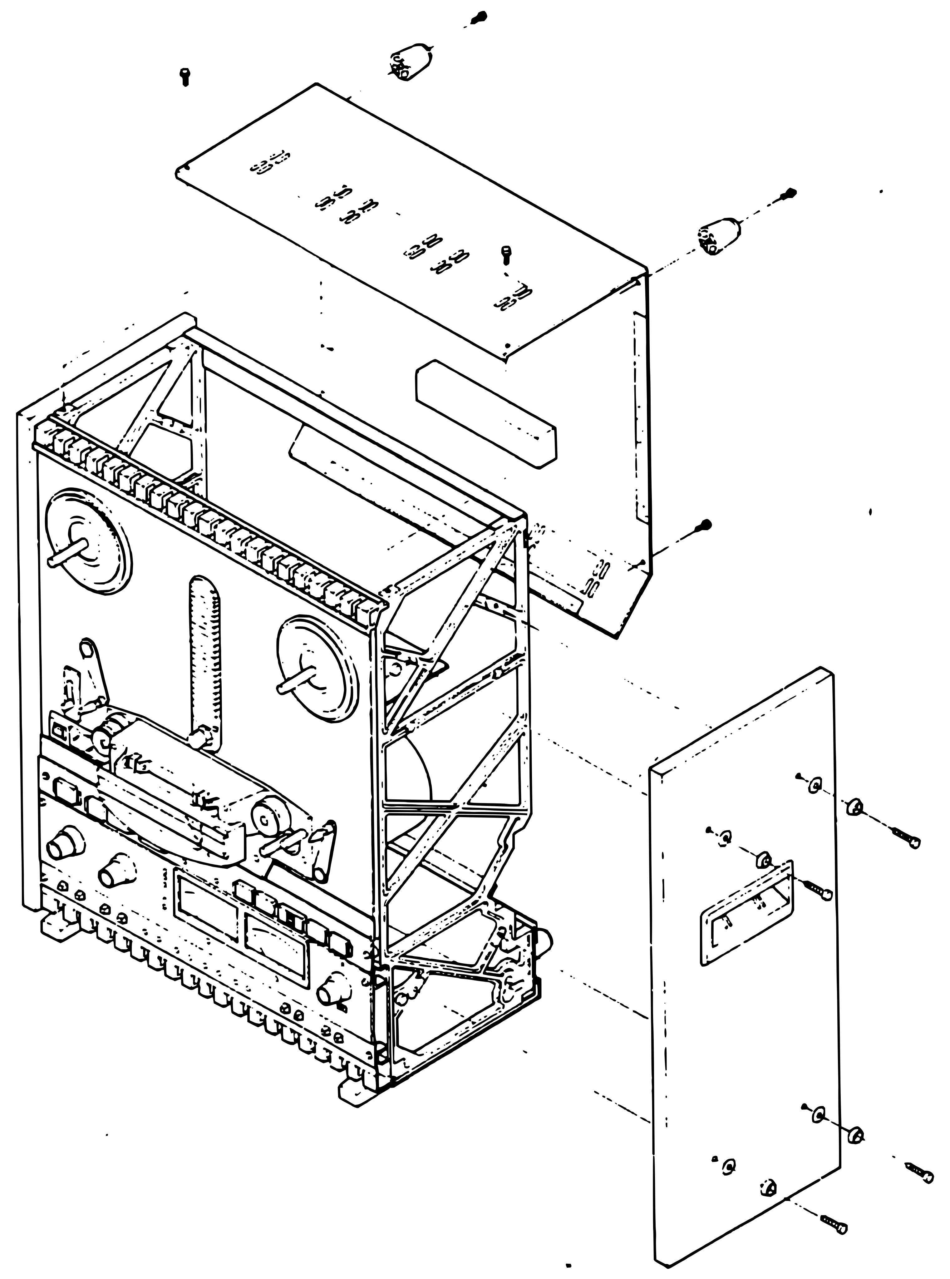 ⤢ zoomFigure 1 Rear Panel Removal: an exploded view of the BII cabinet, with the rear cover drawn away from the back of the cabinet with its screws and two cylindrical fittings, and a side panel drawn away from the right side with its screws and washers
- Clean and demagnetize the Heads, Lifters, and Tape Guides.
- Remove the Rear Cover (refer to Figure 1).
- Remove the 6 screws (3 on each side) which attach the Control PCB (PB-46Q) to the chassis and swing the PCB down to horizontal.
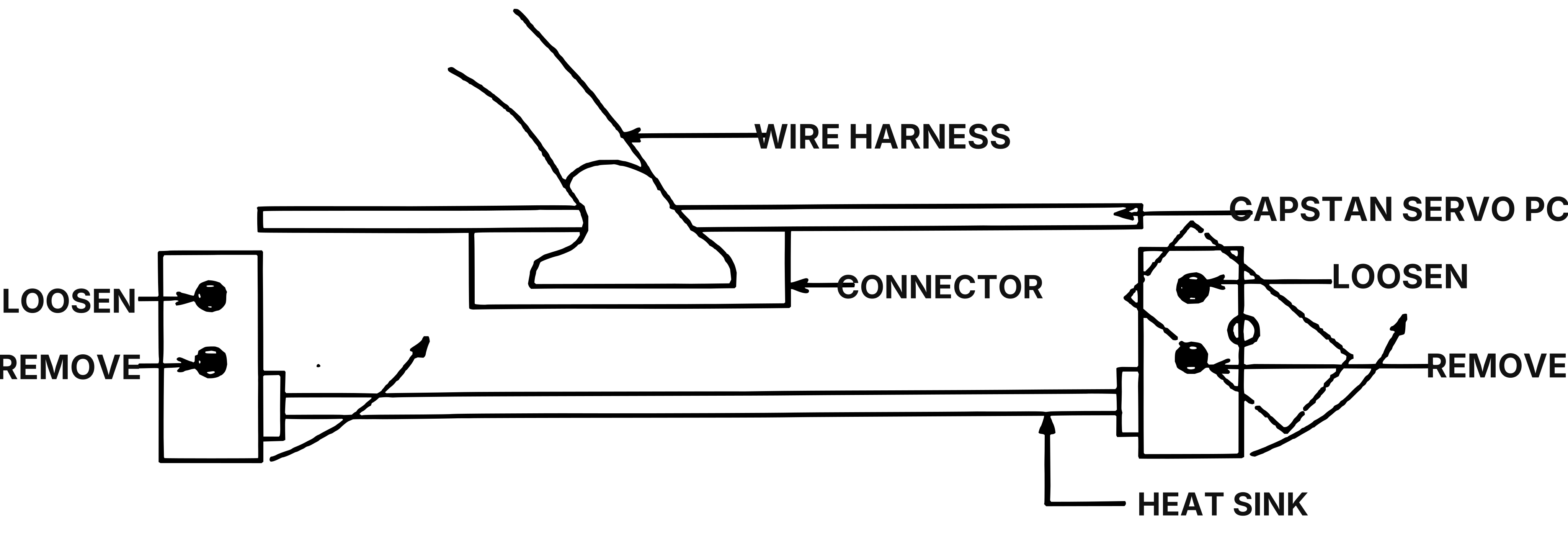 ⤢ zoomFigure 2 Capstan Servo PCB Removal: the Capstan Servo PCB seen edge-on with the wire harness and connector at the top; at each end a bracket with one screw marked LOOSEN and one marked REMOVE, and curved arrows showing the brackets swung up; the heat sink along the bottom
- Remove the 2 screws which attach the bottom of the Capstan Servo PCB brackets, and loosen the 2 top screws to allow the brackets to be rotated up out of the way, and slide the Capstan Servo PCB out of its Card Guides enough to gain access to the adjustment trimmers (refer to Figure 2).
Connect the Power cord and turn ON the power to the machine:
- Thread the machine with the 7.5 ips 3150 Hz Speed and Flutter Test tape.
- Set the REEL SIZE selector to the Large Reel position, set the TAPE SPEED selector to the Low (7-1/2 ips) position, and set the SOURCE/TAPE selectors to Tape monitor.
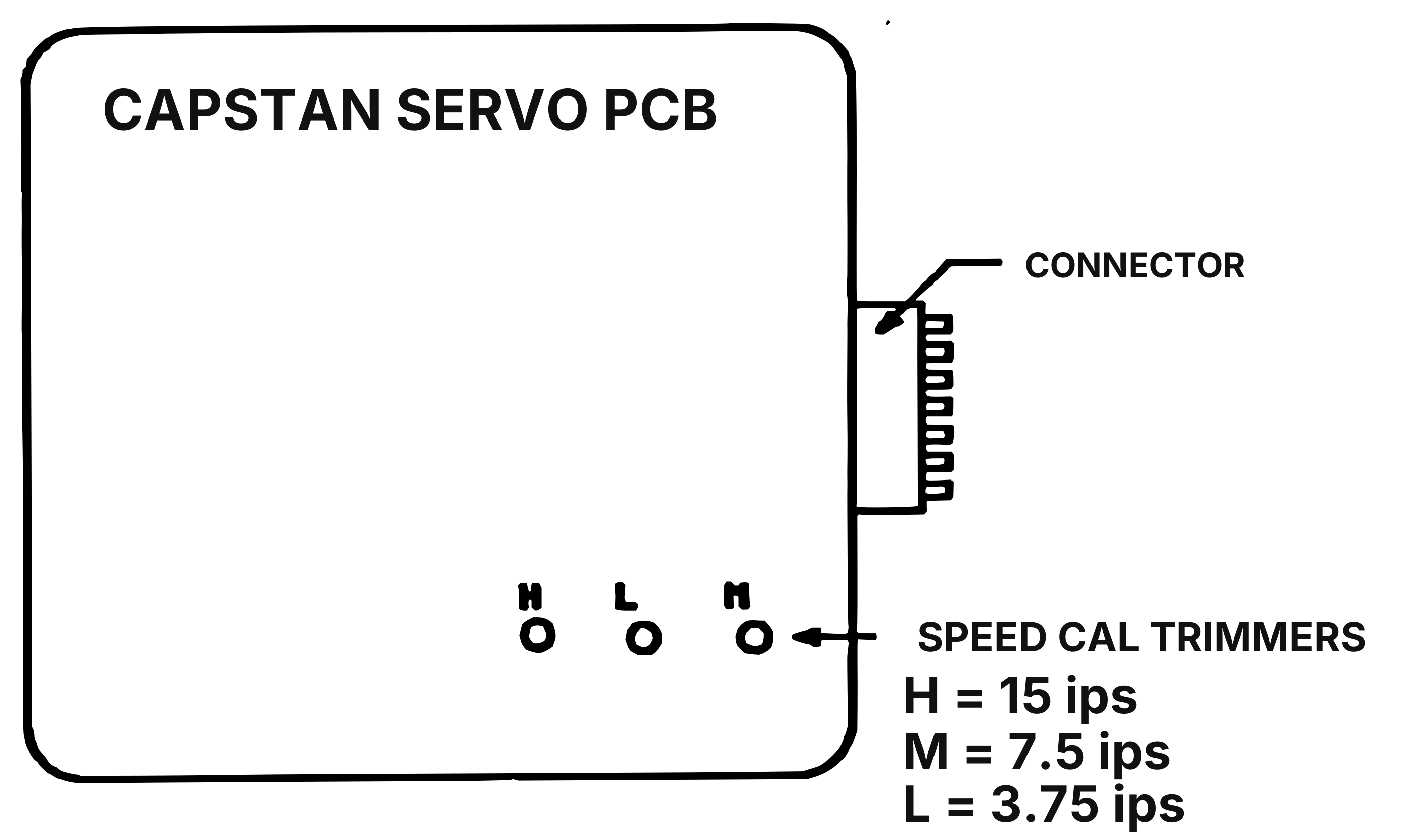 ⤢ zoomFigure 3 Location of Trimmers on Capstan Servo PCB: the Capstan Servo PCB with its edge connector at the right and the three SPEED CAL TRIMMERS in a row near the bottom, labeled H, L and M, with the legend giving H = 15 ips, M = 7.5 ips, L = 3.75 ips
- Wind the tape until there is an equal amount of tape on Supply and Take-Up reels.
- Connect the Frequency Counter to either channel Audio Output connector on the rear panel.
- Place the machine in Play mode, and adjust the M trimmer on the Capstan Servo PCB until the counter indicates 3150 Hz ±5 Hz. Refer to Figure 3 for the location of the trimmer.
- Stop the tape, and set the front Panel Speed selector to the High (15 ips) position. Rewind the tape until there is an equal amount of tape on both reels.
- Place the machine in Play mode, and adjust the H trimmer on the Capstan Servo PCB until the counter indicates 6300 Hz ±10 Hz.
This completes the Speed Calibration procedure for the MX-5050 BII.
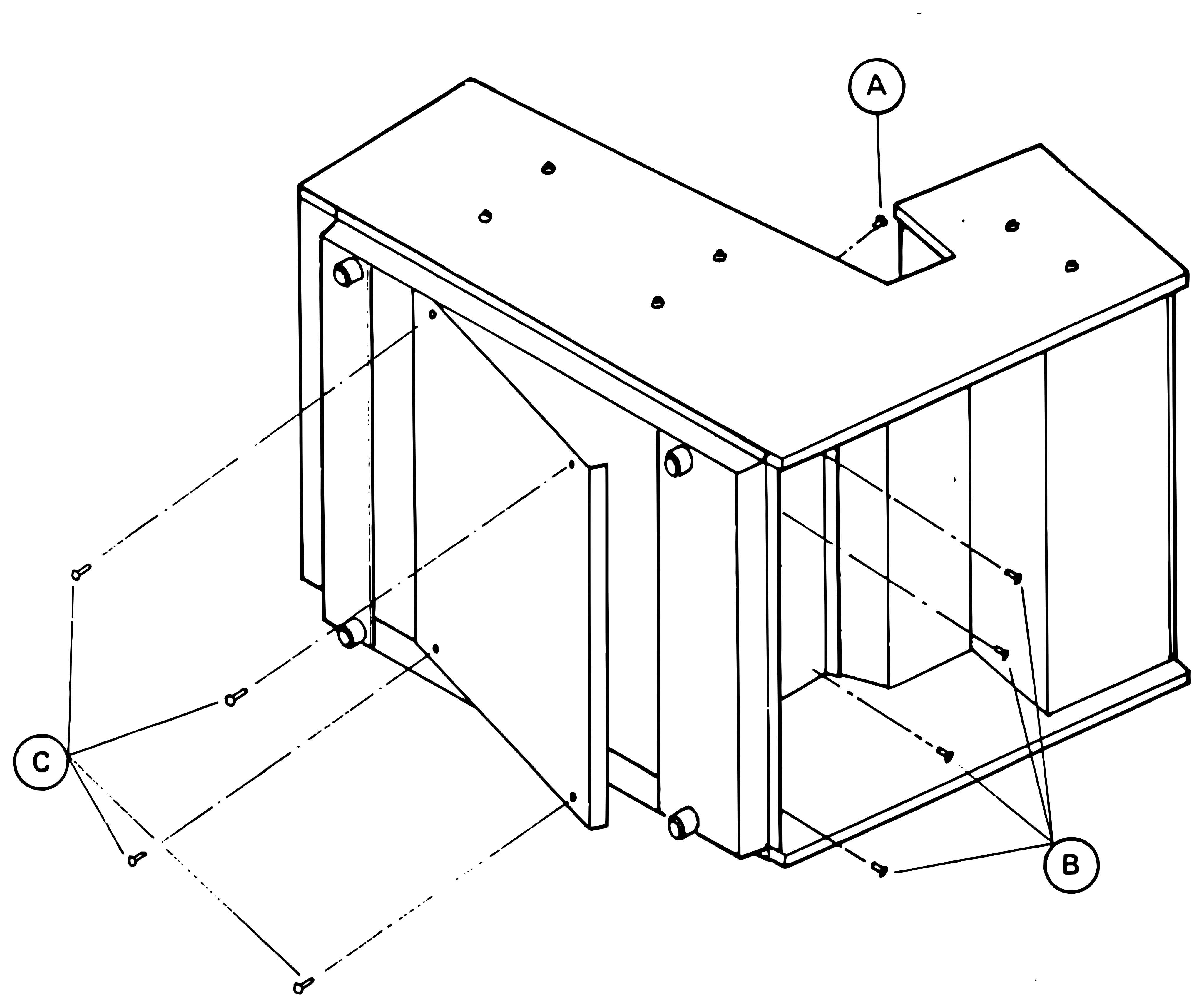 ⤢ zoomFigure 4 Opening the Transport: an exploded view of the transport chassis laid on its side, with the bottom panel swung out at the left and its four screws marked C, a single screw marked A at the top, and the screws marked B at the open right-hand end
2.2 MX-5050 MkIII-2 SPEED CALIBRATION↑ TOP
With the Power to the machine turned OFF:
- Lay the machine on its left side (as shown in Figure 4) so that the left (Supply) reel can rotate freely when an empty reel is mounted.
- Remove the 4 screws marked "C" in Figure 4, and swing the bottom panel out.
- Clean and demagnetize the Heads, Lifters and Tape Guides.
Connect the Power cord and turn ON the power to the machine:
- Thread the machine with the 7-1/2 ips 3150 Hz Speed/Flutter Test tape.
- On the Transport, set the REEL SIZE selector to the Large Reel position, set the TAPE SPEED selector to the Low (7-1/2 ips) position, and, on the Overbridge, set the SOURCE/TAPE selectors to Tape monitor.
- Wind the tape until there is an equal amount of tape on Supply and Take-Up reels.
- Connect the Frequency Counter to either channel Audio Output connector on the rear panel.
- Place the machine in Play mode, and adjust the M trimmer on the Capstan Servo PCB until the counter indicates 3150 Hz ±5 Hz. Refer to Figure 3 for the location of the trimmer.
- Stop the tape and set the front panel TAPE SPEED selector to the High (15 ips) position. Rewind the tape until there is an equal amount of tape on both reels.
- Place the machine in Play mode, and adjust the H trimmer on the Capstan Servo PCB until the counter indicates 6300 Hz ±10 Hz.
This completes the Speed Calibration procedure for the MX-5050 MkIII-2
2.3 MX-5050 MkIII-2 SERVO OFFSET ADJUSTMENT↑ TOP
This procedure is necessary only when the MX-5050 MkIII-2 is to be used with a device such a Synchronizer or Resolver which externally controls the speed of the capstan motor using an external DC control voltage. Refer to the Transport Wiring diagram in the MX-5050 MkIII Manual, or the OTARI Synchronizer Interface Information booklet for information regarding the connector pinout for the LOCATOR connector on the rear panel. Refer to Figure 5 for Location of Switches and Trimmer.
- If the machine is not already open from the previous procedure, refer to Steps 1 and 2 in Section 2.2 to gain access to the Transport Control PCB.
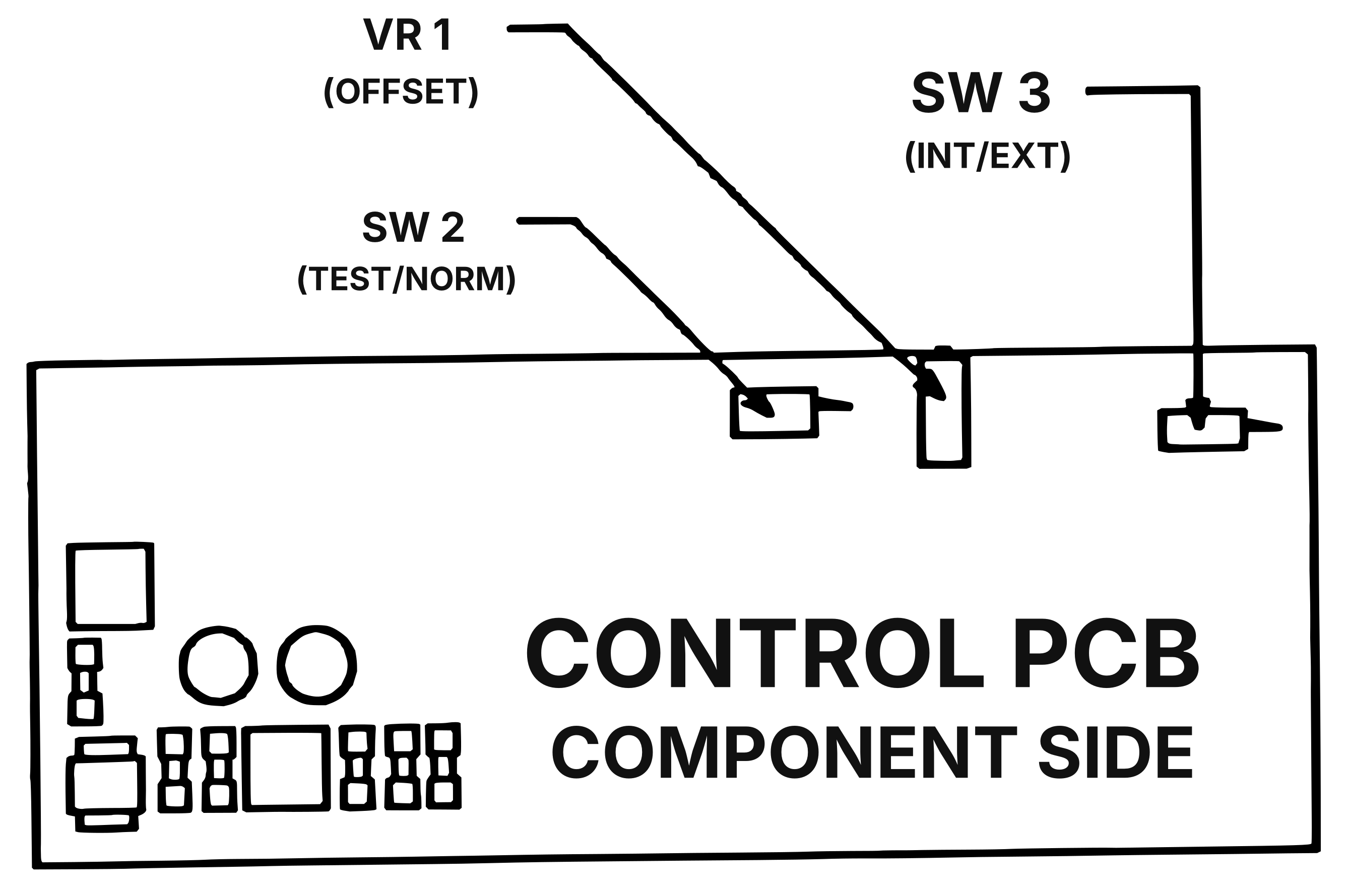 ⤢ zoomFigure 5 Location of Switches and Trimmer on Control PCB: the Control PCB (component side), with labels VR 1 (OFFSET), SW 2 (TEST/NORM) and SW 3 (INT/EXT) above the board, each with a leader to its trimmer or switch along the top edge, right of centre
- Set the SPEED switch to the High position, set the REEL SIZE switch to the Large position, and set the SOURCE/TAPE switch to the Tape position.
- Connect the Frequency Counter to either channel OUTPUT connector on the rear panel.
- On the Transport Control PCB, set SW 2 to the Test position, and set SW 3 to the Internal position. Thread the machine with the 7.5 ips Speed/Flutter Test tape.
- Place the machine in Play mode and note the reading on the Frequency Counter (it should read 6300 Hz).
- Set SW 3 to the External position and adjust VR 1 (DC Offset Adjustment) so the counter reads the same as in Internal position ±2 Hz.
- After adjustment is complete, set SW 2 to the Normal position and set SW 3 to the External position for operation with the synchronizer.
NOTE: It is necessary to set SW 3 to the Internal position for Normal operation without the synchronizer.