MX-5050 MKIV-2 and BIII-2 Operation and Maintenance Manual — Digital Edition · Part 10 · PDF pages 136,138-140
Appendix
- Block Diagram
- Troubleshooting Hints (Electronics)
- Troubleshooting Hints (Transport)
Block Diagram↑ TOP
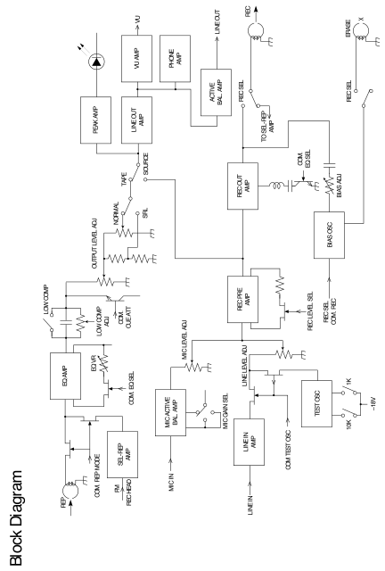 ⤢ zoomBlock Diagram: a signal-flow schematic of the record/reproduce electronics, set sideways on the printed page (open the linked SVG at full size to read it in its own orientation). Reproduce path: the REP head input and the FM/REC HEAD-fed SEL-REP AMP (COM. REP MODE switch) drive the EQ AMP, trimmed by EQ VR under COM. EQ SEL, then a LOW COMP switch and LOW COMP ADJ pot (gated by COM. CUE ATT) lead into the OUTPUT LEVEL ADJ divider (NORMAL/SRL switch) and the TAPE/SOURCE switch. Record input path: MIC IN drives the MIC ACTIVE BAL. AMP (MIC GAIN SEL switch, MIC LEVEL ADJ pot); LINE IN drives the LINE IN AMP (LINE LEVEL ADJ pot, also fed by COM TEST OSC from the TEST OSC block, itself switched 10K/1K off a –18V rail). Both level-adjusted signals join at the REC PRE AMP (REC LEVEL SEL trim) and feed the REC OUT AMP; the TAPE/SOURCE switch's SOURCE position monitors this same REC PRE AMP/REC OUT AMP junction. REC OUT AMP output splits to: a TO SEL-REP AMP feedback line; a REC SEL switch driving the REC (record) head; and, through a COM. EQ SEL bias trap, the BIAS ADJ pot fed by the BIAS OSC (selected by REC SEL/COM. REC), which also drives the ERASE head through a second REC SEL switch. Monitor/output path: the TAPE/SOURCE switch's output drives the PEAK AMP (to a peak-indicator LED) and the LINE OUT AMP, which feeds the VU AMP (VU meter output), the PHONE AMP and a separate ACTIVE BAL. AMP producing a balanced LINE OUT.
Troubleshooting Hints (Transport)↑ TOP
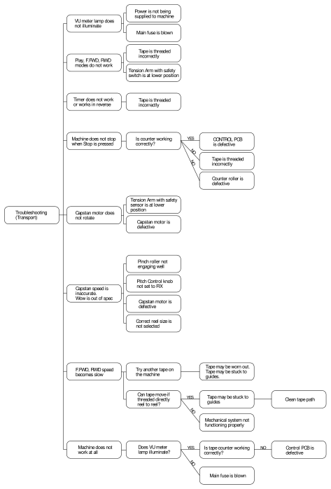 ⤢ zoomTroubleshooting Hints (Transport): a troubleshooting decision tree rooted at "Troubleshooting (Transport)", branching to eight symptoms, each with its checks or causes (open the linked SVG at full size to read every box). VU meter lamp does not illuminate: power is not being supplied to the machine; or the main fuse is blown. Play, F.FWD, RWD modes do not work: tape is threaded incorrectly; or the Tension Arm with its safety switch is at the lower position. Timer does not work or works in reverse: tape is threaded incorrectly. Machine does not stop when Stop is pressed: is the counter working correctly? If YES, the CONTROL PCB is defective; if NO, either the tape is threaded incorrectly or the counter roller is defective. Capstan motor does not rotate: the Tension Arm with its safety sensor is at the lower position; or the capstan motor is defective. Capstan speed is inaccurate, wow is out of spec: the pinch roller is not engaging well; the Pitch Control knob is not set to FIX; the capstan motor is defective; or the correct reel size is not selected. F.FWD, RWD speed becomes slow: try another tape on the machine — the tape may be worn out or stuck to the guides; and check whether the tape can move if threaded directly reel to reel — if YES, the tape may be stuck to the guides (clean the tape path); if NO, the mechanical system is not functioning properly. Machine does not work at all: does the VU meter lamp illuminate? If YES, is the tape counter working correctly? — if NO, the Control PCB is defective; if NO (lamp does not illuminate), the main fuse is blown.
Troubleshooting Hints (Electronics)↑ TOP
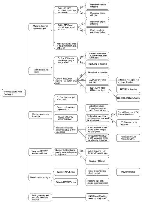 ⤢ zoomTroubleshooting Hints (Electronics): a troubleshooting decision tree rooted at "Troubleshooting Hints Electronics", branching to six symptoms, each with its checks or causes (open the linked SVG at full size to read every box). Machine does not reproduce tape: set to SEL-REP and check if the machine reproduces — YES, reproduce head is defective; NO, reproduce amp is defective; set to INPUT and check if the input signal is output — YES, reproduce amp is defective; NO, power supply or output amp is bad; also make sure the output knob is not at minimum and SRL is off. Machine does not record: confirm if the VU meter operates properly in INPUT mode — YES, proceed to the next step (confirm REC LED illumination); NO, input amp is defective; confirm if the REC LED (AMP & REC button lamp) lights — YES, bias circuit is defective; NO and only the AMP LED does not light, CONTROL PCB, AMP PCB or cables are defective; NO and both AMP & REC LEDs do not light, either the REC SW is defective or the CONTROL PCB is defective. Frequency response is not flat: confirm that the tape path is not dirty; if reproduce frequency response is bad, adjust reproduce frequency response with a repro test tape; if record frequency response is bad, confirm that the tape being used is the same as the tape used for adjustment — YES, check EQ and bias (if OK, amp or head is bad); NO, EQ and bias need to be adjusted; confirm if the frequency response is bad at only one speed — if bad at one speed, readjust for that speed; if bad at all frequencies, check for the following problems: heads are dirty, or amp is defective. Input and REC/REP levels are different: confirm that the tape being used is the same as the tape used for adjustment — YES, adjust bias and REC levels with the correct tape; NO, readjust REC level. Noise in recorded signal: noise in INPUT mode — noisy even with input disconnected means the input amp is bad; noise in REC/REP mode means the head and tape path should be demagnetized. Mixing console and recorder levels are different: INPUT Level Matching needs to be adjusted.