MX-5050 MKIV-2 and BIII-2 Operation and Maintenance Manual — Digital Edition · Part 9 · PDF pages 96-134
Exploded Views and Parts List
The following exploded view drawings and parts lists are provided for service reference. Each drawing has its own parts list followed with the same key number and title.
When ordering parts, give a full description, using both the part number and the name of the part. If there seems to be a discrepancy between the drawings herein and your MX-5050, contact OTARI. We assume no liability for improper servicing due to changes and improvements which we make that subsequently render certain of these documents obsolete.
BIII↑ TOP
| No. | Assembly Name | Parts No. | Page |
|---|---|---|---|
| 1. | Case Assembly | K1168 | 9-2 |
| 2. | Chassis Assembly | T0067 | 9-4 |
| 3. | Head Assembly | KH-44K | 9-6 |
| 4. | Reel Assembly | KW-41J | 9-8 |
| 5. | Pinch Roller Assembly | KP-4X | 9-10 |
| Capstan Assembly | KC-41H | ||
| Shifter Assembly | KR-4W | ||
| 6. | Tension Arm Assembly | KA-4X/KA-4Y | 9-12 |
| Impedance Roller Ass'y | KI-4T | ||
| Timer Assembly | ZA-95G | ||
| 7. | Control Assembly | CB-23U | 9-14 |
| 8. | Amplifier Assembly | A1220 | 9-16 |
| 9. | Connector Panel Ass'y | CB-792 | 9-18 |
MKIV-2
| No. | Assembly Name | Parts No. | Page |
|---|---|---|---|
| 1. | Case Assembly | K1170 | 9-20 |
| 2. | Chassis Assembly | T0069 | 9-22 |
| 3. | Head Assembly | KH-44K | 9-24 |
| 4. | Reel Assembly | KW-41J | 9-26 |
| 5. | Pinch Roller Assembly | KP-4X | 9-28 |
| Capstan Assembly | KC-41H | ||
| Shifter Assembly | KR-4W | ||
| 6. | Tension Arm Assembly | KA-4X/KA-4Y | 9-30 |
| Impedance Roller Assembly | KI-4T | ||
| Timer Assembly | ZA-95G | ||
| 7. | Control Assembly | CB-23U | 9-32 |
| 8. | Amplifier Assembly | A1221 | 9-34 |
| 9. | Amp. Connector Assembly | A1221 | 9-36 |
| 10. | Connector Panel Assembly | CB-794 | 9-38 |
Case Assembly: K1168↑ TOP
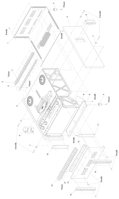 ⤢ zoomCase Assembly: K1168: isometric exploded view of the BIII case, showing the top cover, side panels, carrying handle, rear panel with connector-panel cutout, bottom panel and the four case feet, with each part numbered 1-15 and its fastener code (B4x6B, B4x8B, C4x25B, PS4x8, TS3x8, PS3x6) on a leader line.
| No. | Description | Parts No. |
|---|---|---|
| 1 | Rear Cover Assembly | K1168-A |
| 2 | Grille, Ventilation | CY5001A |
| 3 | Plate C | K102911 |
| 4 | Foot | CY4013 |
| 5 | Panel, Side | K116802 |
| 6 | Hundle | CY1004 |
| 7 | Washer, Trim | KZ6C028 |
| 8 | Connector Panel Assembly | CB792 |
| 9 | Panel, Rear | A106204 |
| 10 | Plate, L | K102909 |
| 11 | Plate, R | K102910 |
| 12 | Grille, Ventilation | CY5001A |
| 13 | Plate | K102907 |
| 14 | Panel, Bottom | K102906A |
| 15 | Foot, Case | CY4011-A |
Chassis Assembly: T0067↑ TOP
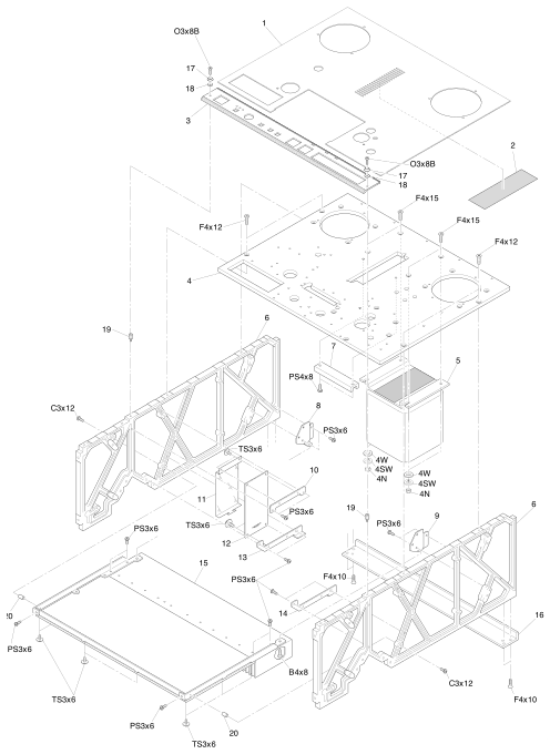 ⤢ zoomChassis Assembly: T0067: isometric exploded view of the BIII chassis, showing the deck cover panel, top panel with the control-assembly cutout, power transformer, main frame, fuse and control PCB brackets and covers, and the deck cover blind, with each part numbered 1-20 and its fastener code (O3x8B, F4x12, F4x15, F4x10, PS3x6, PS4x8, TS3x6, C3x12, B4x8, and washer codes 4W/4SW/4N) on a leader line.
| No. | Description | Parts No. |
|---|---|---|
| 1 | Panel, Deck Cover | T006702 |
| 2 | Blind | T006703 |
| 3 | Control Assembly | CB-23U |
| 4 | Panel, Top | T006701 |
| 5 | Transformer, Power | TF11030 |
| 6 | Frame | T006708 |
| 7 | Angle | T506405 |
| 8 | Bracket L | T007104 |
| 9 | Bracket R | T007105 |
| 10 | Bracket | T006705 |
| 11 | Cover, Fuse | T005306 |
| 12 | FUSE PCB Assembly | PB-7VCA |
| 13 | Bracket L | T006710 |
| 14 | Bracket R | T006709 |
| 15 | CONTROL PCB Assembly | PB-4RNA |
| 16 | Angle, Frame | T506104 |
| 17 | Washer, Trim | KZ6C051 |
| 18 | Washer | KZ6C011 |
| 19 | Stud | KZ9L080A |
| 20 | Stud | KZ9A095B |
Head Assembly: KH-44K↑ TOP
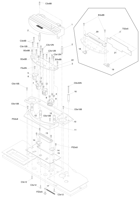 ⤢ zoomHead Assembly: KH-44K: isometric exploded view of the BIII head block, showing the head housing assembly, head base, head-adjustment spring, guide posts, the erase/record/reproduce head sub-assembly (KH-44KA), the front housing cover, tape guide and connector bracket, with an inset detail of the PCB brackets and the HEAD RELAY PCB assembly, each part numbered 1-22 and its fastener code (C3x8B, B3x8B, C3x6B, C3x12N, C3x12B, F3x6N, O3x30N, O3x10B, PS3x8, PZ3x6, C3x12, TS3x6) on a leader line.
| No. | Description | Parts No. | Notes |
|---|---|---|---|
| 1 | Head Housing Assembly | KH-4Y-A | |
| 2 | Stud | KH4Y009 | |
| 3 | Base, Head | KH0C047 | Head Sub Assembly KH-44KA |
| 4 | Spring, Head Adjustment | GS2016 | |
| 5 | Bracket, Head | KH0D178 | |
| 6 | Post, Guide | KG4E001 | |
| 7 | Erase Head Assembly, 1/4" 2CH | GH4E082B | |
| 8 | Record Head Assembly, 1/4" 2CH | GH4R005B | |
| 9 | Reproduce Head Assembly, 1/4" 2CH | GH4P027B | |
| 10 | Cover, Housing | KH0F038 | |
| 11 | Head Housing,Front | KH0F037 | |
| 12 | Guide, Tape | KG4A003 | |
| 13 | Connector | CN314002 | |
| 14 | Bracket, Connector | KH4Y004 | |
| 15 | Plate, Shield | KH4Y001A | |
| 16 | Pole, Guide | KG6E020 | |
| 17 | Clamp, Cable | PZ1G053 | |
| 18 | Bracket L, PCB | KH41I01 | Head Sub Assembly KH-44KA |
| 19 | Bracket R, PCB | KH41I02 | |
| 20 | Cover, Protection | KH41T02 | |
| 21 | HEAD, RELAY PCB Assembly | PB-78IAB | |
| 22 | Washer, Polyslider | F523030 |
Reel Assembly : KW-41J↑ TOP
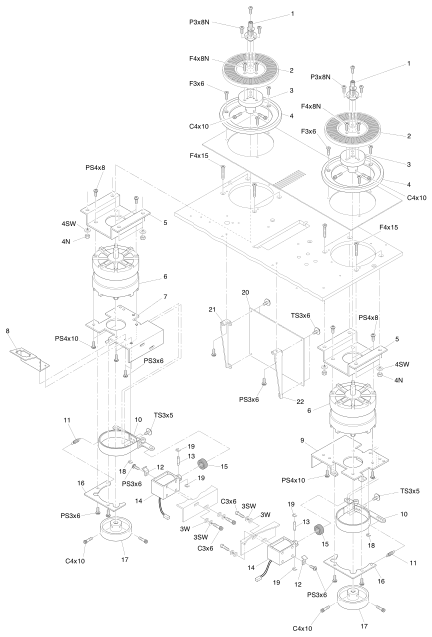 ⤢ zoomReel Assembly : KW-41J: isometric exploded view of the two BIII reel motor assemblies (mirrored left and right), showing the reel shaft and reel table assemblies, the reel motor and its mounting bracket, the brake band assembly with its left and right brake bases, the reel-motor-drive PCB assembly and its mounting brackets, with each part numbered 1-22 and its fastener code (P3x8N, F4x8N, F3x6, C4x10, F4x15, PS4x8, PS4x10, TS3x6, TS3x5, PS3x6, C3x6, and washer codes 3W/3SW/4SW/4N) on a leader line.
| No. | Description | Parts No. |
|---|---|---|
| 1 | Reel Shaft Assembly | KW-41DG |
| 2 | Reel Table Assembly | KW-41EA |
| 3 | Holder, Reel Table | KW0B056 |
| 4 | Protector, Reel | KW0H007A |
| 5 | Bracket, Reel Motor | KW0G016 |
| 6 | Motor, Reel | MR1C005 |
| 7 | Base L , Brake | KW0G013 |
| 8 | Bracket, Connector | KW41J01 |
| 9 | Base R, Brake | KW0G012 |
| 10 | Brake Band Assembly | KW-4J-A |
| 11 | Spring | GS1175 |
| 12 | Stopper, Cable | KZ3A047 |
| 13 | Pin, Solenoid | KZ5A003 |
| 14 | Solenoid | GP1F03 |
| 15 | Damper | PZ1B049 |
| 16 | Guide, Brake | KW4B001 |
| 17 | Drum, Brake | KW0A012 |
| 18 | Ring, E type | F74TE15 |
| 19 | Ring, E type | F74TE09 |
| 20 | REEL MOTOR DRIVE PCB Assembly | PB-4RNA |
| 21 | Bracket A, Reel Motor Draive PCB | T005317 |
| 22 | Bracket B, Reel Motor Draive PCB | T005318 |
Pinch Roller Assembly: KP-4X↑ TOP
Capstan Assembly: KC-41H↑ TOP
Shifter Assembly: KR-4W↑ TOP
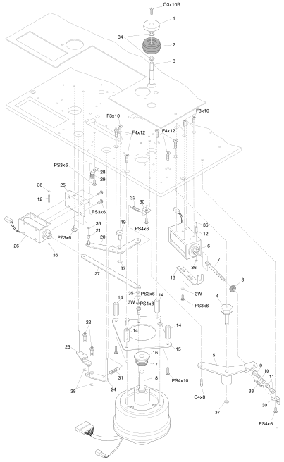 ⤢ zoomPinch Roller Assembly: KP-4X / Capstan Assembly: KC-41H / Shifter Assembly: KR-4W: isometric exploded view of the combined pinch-roller, capstan and shifter mechanism, showing the pinch roller arm assembly and its solenoid, the capstan motor, the shifter link assembly with its lifter arms A and B and shifter solenoid, with each part numbered 1-38 and its fastener code (O3x10B, F3x10, F4x12, PS3x6, PS4x6, PS4x8, PS4x10, PZ3x6, C4x8, and washer code 3W) on a leader line.
| No. | Description | Parts No. |
|---|---|---|
| 1 | Cap, Pinch Roller | KP0C034 |
| 2 | Pinch Roller Assembly | KP-4S-B |
| 3 | Shaft, Pinch Roller | KP0B060 |
| 4 | Shaft, Arm | KP4L001 |
| 5 | Pinch Roller Arm Assembly | KP-4X-A |
| 6 | Solenoid | GP1B12 |
| 7 | Screw, Adjustment | KZ6A113 |
| 8 | Damper | PZ1C021 |
| 9 | Washer Spherical | KP0G004 |
| 10 | Spring | GS2163 |
| 11 | Nut, Dubble | F517-4 |
| 12 | Pin, Solenoid | KZ5A003 |
| 13 | Stopper, Solenoid | KZ2A016 |
| 14 | Stud | KZ9I250A |
| 15 | Bracket, Motor | KC4H001 |
| 16 | Cap, Dust | KC0B029 |
| 17 | Ring | PZ1C130 |
| 18 | Motor, Capstan | MR-1L |
| 19 | Shaft, Link Arm | KR4W005 |
| 20 | Shifter Link Assembly | KR-4W-A |
| 21 | Collar | KZ7C109 |
| 22 | Shaft, Arm | KR4B001 |
| 23 | Arm A, Lifter | KR0B005 |
| 24 | Arm B, Lifter | KR0B006 |
| 25 | Bracket,Shifter Solenoid | KR4W007 |
| 26 | Solenoid | GP1A09 |
| 27 | Arm, Link | KR4W004 |
| 28 | Angle | KZ3A042 |
| 29 | Pipe, Rubber | PZ1C174 |
| 30 | Hook | KZ3A167 |
| 31 | Spring | GS1185 |
| 32 | Spring | GS1028-A |
| 33 | Spring | GS1149 |
| 34 | Washer, Polyslider | F524060 |
| 35 | Stud | KZ7A823 |
| 36 | Ring, E type | F74TE09 |
| 37 | Ring, E type | F74TE20 |
| 38 | Ring, E type | F74TE15 |
Tension Arm Assembly: KA-4X/KA-4Y↑ TOP
Impedance Roller Assembly: KI-4T↑ TOP
Timer Assembly: ZA-95G↑ TOP
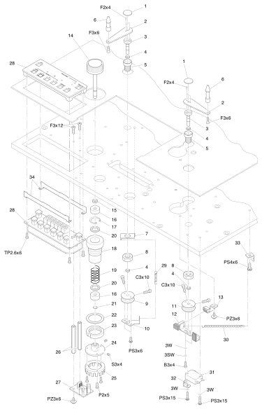 ⤢ zoomTension Arm Assembly: KA-4X/KA-4Y / Impedance Roller Assembly: KI-4T / Timer Assembly: ZA-95G: isometric exploded view of the combined tension-arm, impedance-roller and timer mechanism, showing the tension arm and its switch actuator and magnet assembly, the impedance roller sub-assembly (KI-4J-A), the roller tacho PCB assembly and tacho disk, and the timer display assembly with its two rows of buttons and its printed panel legend (SET, ZERO, SEARCH with H/M/S and 1/2/3, REPEAT, CLR, TAPE SPEED with L/H, TIME-IPS-%), with each part numbered 1-34 and its fastener code (F2x4, F3x6, F3x12, TP2.6x6, C3x10, PS3x6, PS4x6, PZ3x6, P2x5, PS3x15, and washer codes 3W/3SW/B3x4/S3x4) on a leader line.
| No. | Description | Parts No. | Notes |
|---|---|---|---|
| 1 | Cap, Arm | KA0C005 | |
| 2 | Arm, Tension | KA0A017A | |
| 3 | Shaft, Arm | KA4J001 | |
| 4 | Washer, Polyslider | F524-5 | |
| 5 | Holder, Arm | KA0B008 | |
| 6 | Guide, Tape | KG4D007 | |
| 7 | Hook, Spring | KZ3A024 | |
| 8 | Nut | KZ6D004 | |
| 9 | Hook A, Spring | KA0E017 | |
| 10 | Stopper, Arm | KA4X001 | |
| 11 | Hook B, Spring | KA0E005 | |
| 12 | Switch Actuator Assembly | KA-4K-B | |
| 13 | Magnet Assembly | KA-4K-C | |
| 14 | Roller Assembly | KI-4J-B | Impedance Roller Sub Assembly KI-4J-A |
| 15 | Collar | KZ7C057 | |
| 16 | Bearing | BA1Z022 | |
| 17 | Ring | F7017 | |
| 18 | Holder | KI0B014 | |
| 19 | Spring | GS2077 | |
| 20 | Washer | KZ6C057 | |
| 21 | Ring, Shaft | F7206 | |
| 22 | Washer | KI0H024 | |
| 23 | Nut, Holder | KI0H025 | |
| 24 | Boss | KI4T001 | |
| 25 | Disk, Tacho | SR3Z033 | |
| 26 | Stud | KZ9H480C | |
| 27 | ROLLER TACHO PCB Assembly | PB-4HCA | |
| 28 | Timer Display Assembly | ZA-95G | |
| 29 | Spring | GS1025 | |
| 30 | Spring | GS1048 | |
| 31 | Switch, Micro | WH51027 | |
| 32 | Hook, Spring | KZ3A023 | |
| 33 | Hook | KZ3A167 | |
| 34 | Bracket | KZ2A165 |
Control Assembly: CB-23U↑ TOP
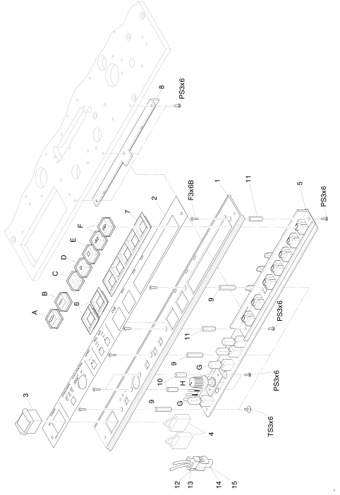 ⤢ zoomControl Assembly: CB-23U: isometric exploded view of the BIII control panel, showing the control panel and its overlay sheet, the power switch, the transport control switch PCB assembly with its eight buttons (CUE, EDIT, RECORD, PLAY, STOP, F.FWD/RWD, the selector switch and the pitch-control knob and cap, lettered A-H), the switch escutcheons and the plug/receptacle connector housings, plus the printed front-panel legend below the buttons (POWER ON/OFF, SPEED MODE EXT/FIX/VARI, PITCH CONTROL UP/DOWN, SPEED L/H, REEL SIZE SUP S/L, T.UP S/L), with numbered items 1-15, lettered items A-H and their fastener codes (PS3x6, TS3x6, F3x6B) on leader lines.
| No. | Description | Parts No. |
|---|---|---|
| 1 | Panel, Control | CB23U01 |
| 2 | Sheet, Control Panel | CB23U02 |
| 3 | Switch, Power | WH42062 |
| 4 | Capacitor, Spark Killer | CZ20001W |
| 5 | TRANSPORT CONTROL SWITCH PCB Assembly | PB-7UZA |
| A | Button, CUE | KN2145 |
| B | Button, EDIT | KN2147 |
| C | Button,RECORD | KN2144 |
| D | Button, PLAY | KN2142 |
| E | Button, STOP | KN2141 |
| F | Button, F.FWD , RWD | KN2143 |
| G | Switch, Selector | KN2184 |
| H | Knob | KN1108 |
| H | Cap, Knob | KN1099 |
| 6 | Escutcheon, Switch | PZ4A026 |
| 7 | Escutcheon, Switch | PZ4A027 |
| 8 | Angle | T006704 |
| 9 | Stud | KZ7B160 |
| 10 | Stud | KZ7B158 |
| 11 | Stud | KZ7B159 |
| 12 | Connector Housing, Plug | CN402029 |
| 13 | Connector Contact, Plug | CN7B-041 |
| 14 | Connector Housing, Receptacle | CN402030 |
| 15 | Connector Contact, Receptacle | CN7B-042 |
Amplifier Assembly: A1220↑ TOP
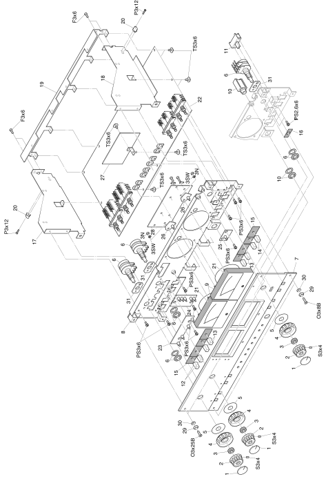 ⤢ zoomAmplifier Assembly: A1220: isometric exploded view of the BIII record/reproduce amplifier module, showing the amp trim panel assembly with its knobs and VU meter, the top panel, the left and right amp frames carrying the REC/REP AMP, LED, REC EQ and VU meter amp PCB assemblies, with each part numbered 1-31 and its fastener code (S3x4, O3x25B, O3x8B, TS3x6, P3x12, F3x6, PS3x6, 1PS2.6x6, and washer codes 3N/3SW) on a leader line.
| No. | Description | Parts No. |
|---|---|---|
| 1 | Cap, Knob | KN1102 |
| 2 | Knob | KN1100A |
| 3 | Collar | KZ7C111 |
| 4 | Knob | KZ1063B |
| 5 | Spacer | KZ6C017 |
| 6 | Potentiometer | RV224005 |
| 7 | Amp Trim Panel Assembly | A1220-A |
| 8 | Panel, Amp. Top | A1220-B |
| 9 | VU Meter | ME11005 |
| 10 | Jack, Phone | CN602144 |
| 11 | Switch | WH340013 |
| 12 | Button | KN2095 |
| 13 | Button | KN2094 |
| 14 | Button | KN2093 |
| 15 | Blind | PZ1B012 |
| 16 | Blind | PZ1B010 |
| 17 | Frame L, Amp | A102808 |
| 18 | Frame R, Amp | A102807 |
| 19 | Bracket, PCB | A106206 |
| 20 | Collar | A102809 |
| 21 | Shield, Illumination | PZ1B013 |
| 22 | REC/REP AMP PCB Assembly | PB-1GYA (BIII-2) PB-16EJ (BIII-F) PB-1GYC (BII-2E) |
| 23 | LED PCB Assembly | PB-83AB |
| 24 | LED PCB Assembly | PB-83BB |
| 25 | LED PCB Assembly | PB-83CAA |
| 26 | LED PCB Assembly | PB-81JB |
| 27 | REC EQ PCB Assembly | PB-81QA |
| 28 | VU Meter Amp. PCB Assembly | PB-16DB |
| 29 | Washer, Trim | KZ6C051 |
| 30 | Washer | KZ6C011 |
| 31 | Spacer | A122004 |
Connector Panel Assembly: CB-792↑ TOP
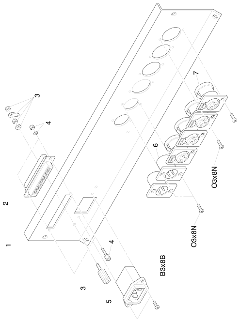 ⤢ zoomConnector Panel Assembly: CB-792: isometric exploded view of the BIII rear connector panel, showing the connector panel, the D-sub 37-pin connector, ground terminal, AC inlet and the row of six XL-type audio connectors (four female, each carrying a printed PUSH tab, and two male), with each part numbered 1-7 and its fastener code (O3x8N, B3x8B) on a leader line.
| No. | Description | Parts No. |
|---|---|---|
| 1 | Panel, Connector | CB79201 |
| 2 | Connector, D sub 37pin | CN237326 |
| 3 | Terminal, Ground | CN901040 |
| 4 | Screw, Lock | CN7B-212 |
| 5 | AC Inlet | CN603012 |
| 6 | Connector, XL type, Male | CN103195 |
| 7 | Connector, XL type, Female | CN103194 |
MKIV-2↑ TOP
Case Assembly: K1170↑ TOP
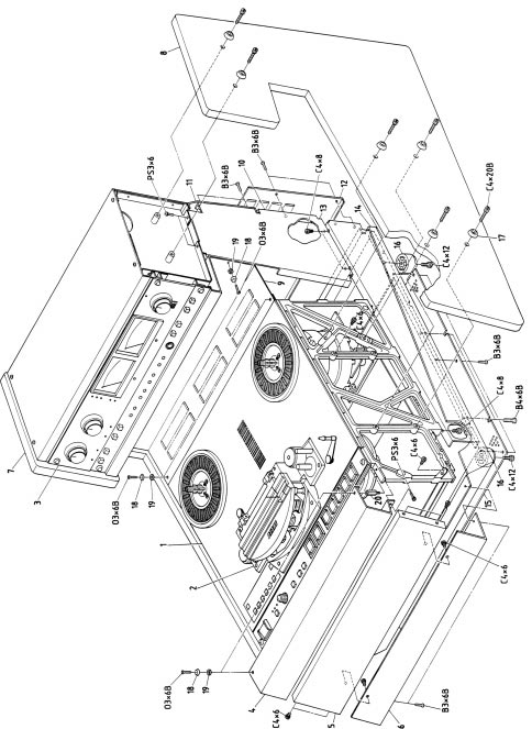 ⤢ zoomCase Assembly: K1170: isometric exploded view of the MKIV-2 case, showing the top cover panels, side panels with the control-panel and VU-meter cutouts, rear panel, bottom frame and case feet, with the connector panel, tape-deck, head and amplifier assemblies shown in place, each part numbered 1-20 and its fastener code (O3x6B, PS3x6, C4x6, C4x8, C4x12, C4x20B, B3x6B, B4x6B) on a leader line.
| No. | Description | Parts No. |
|---|---|---|
| 1 | Tape Deck Assembly | T0069 |
| 2 | Head Assembly | KH-44K |
| 3 | Audio Amplifier Assembl | A1221 |
| 4 | Cover, Front | K117001 |
| 5 | Cover, Front | K117002 |
| 6 | Cover, Under | K117003 |
| 7 | Panel A, Side | K117201 |
| 8 | Panel B, Side | K117202 |
| 9 | Cover, Ventilation | K117205 |
| 10 | Frame R | K117007 |
| 10' | Frame L | K117006 |
| 11 | Panel, Rear | K117005 |
| 12 | Connector Panel Assembly | CB-794 |
| 13 | Bracket R, Chassis | K117210 |
| 13' | Bracket L, Chassis | K117211 |
| 14 | Frame, Under | K117209 |
| 15 | Cover, Under | K117212 |
| 16 | Foot | CY4058 |
| 17 | Washer, Trim | KZ6C028 |
| 18 | Washer, Trim | KZ6C051 |
| 19 | Washer | KZ6C011 |
| 20 | Stud | KZ9L150A |
Chassis Assembly: T0069↑ TOP
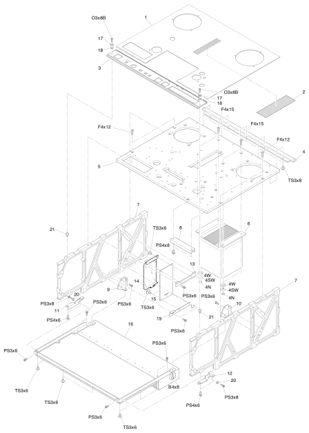 ⤢ zoomChassis Assembly: T0069: isometric exploded view of the MKIV-2 chassis, showing the deck cover panel and blind, the control-assembly cutout, power transformer, main frame, fuse and control PCB brackets and covers, with each part numbered 1-21 and its fastener code (O3x8B, F4x12, F4x15, TS3x6, TS3x8, PS3x6, PS3x8, PS4x6, PS4x8, B4x8, and washer codes 4W/4SW/4N) on a leader line.
| No. | Description | Parts No. |
|---|---|---|
| 1 | Panel, Deck Cover | T006711 |
| 2 | Blind | T006703 |
| 3 | Control Assembly | CB-23U |
| 4 | Angle | T007107 |
| 5 | Panel, Deck | T006701 |
| 6 | Transformer, Power | TF11030 |
| 7 | Frame | T007101 |
| 8 | Angle | T506405 |
| 9 | Bracket L | T007104 |
| 10 | Bracket R | T007105 |
| 11 | Bracket L | T007102 |
| 12 | Bracket R | T007103 |
| 13 | Bracket | T006705 |
| 14 | Cover, Fuse | T005306 |
| 15 | FUSE PCB Assembly | PB-7VCA |
| 16 | CONTROL PCB Assembly | PB-4RMA |
| 17 | Washer, Trim | KZ6C051 |
| 18 | Washer | KZ6C011 |
| 19 | Bracket L | T006710 |
| 20 | Collar, Screw | KZ7C091 |
| 21 | Stud | KZ9L080A |
Head Assembly: KH-44K↑ TOP
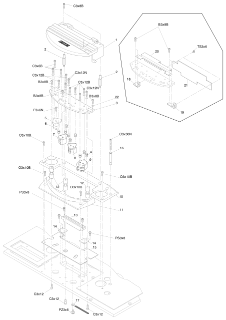 ⤢ zoomHead Assembly: KH-44K: isometric exploded view of the MKIV-2 head block, showing the head housing assembly, head base, head-adjustment spring, guide posts, the erase/record/reproduce head sub-assembly (KH-44KA), the front housing cover, tape guide and connector bracket, with an inset detail of the PCB brackets and the HEAD RELAY PCB assembly, each part numbered 1-22 and its fastener code (C3x8B, B3x8B, C3x6B, C3x12N, C3x12B, F3x6N, O3x30N, O3x10B, PS3x8, PZ3x6, C3x12, TS3x6) on a leader line.
| No. | Description | Parts No. | Notes |
|---|---|---|---|
| 1 | Head Housing Assembly | KH-4Y-A | |
| 2 | Stud | KH4Y009 | |
| 3 | Base, Head | KH0C047 | Head Sub Assembly KH-44KA |
| 4 | Spring, Head Adjustment | GS2016 | |
| 5 | Bracket, Head | KH0D178 | |
| 6 | Post, Guide | KG4E001 | |
| 7 | Erase Head Assembly, 1/4" 2CH | GH4E082B | |
| 8 | Record Head Assembly, 1/4" 2CH | GH4R005B | |
| 9 | Reproduce Head Assembly, 1/4" 2CH | GH4P027B | |
| 10 | Cover, Housing | KH0F038 | |
| 11 | Head Housing, Front | KH0F037 | |
| 12 | Guide, Tape | KG4A003 | |
| 13 | Connector | CN314002 | |
| 14 | Bracket, Connector | KH4Y004 | |
| 15 | Plate, Shield | KH4Y001A | |
| 16 | Pole, Guide | KG6E020 | |
| 17 | Clamp, Cable | PZ1G053 | |
| 18 | Bracket L, PCB | KH41I01 | Head Sub Assembly KH-44KA |
| 19 | Bracket R, PCB | KH41I02 | |
| 20 | Cover, Protection | KH41T02 | |
| 21 | HEAD, RELAY PCB Assembly | PB-78IAB | |
| 22 | Washer, Polyslider | F523030 |
Reel Assembly : KW-41J↑ TOP
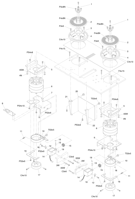 ⤢ zoomReel Assembly : KW-41J: isometric exploded view of the two MKIV-2 reel motor assemblies (mirrored left and right), showing the reel shaft and reel table assemblies, the reel motor and its mounting bracket, the brake band assembly with its left and right brake bases, the reel-motor-drive PCB assembly and its mounting brackets, with each part numbered 1-22 and its fastener code (P3x8N, F4x8N, F3x6, C4x10, F4x15, PS4x8, PS4x10, TS3x6, TS3x5, PS3x6, C3x6, and washer codes 3W/3SW/4SW/4N) on a leader line.
| No. | Description | Parts No. |
|---|---|---|
| 1 | Reel Shaft Assembly | KW-41DG |
| 2 | Reel Table Assembly | KW-41EA |
| 3 | Holder, Reel Table | KW0B056 |
| 4 | Protector, Reel | KW0H007A |
| 5 | Bracket, Reel Motor | KW0G016 |
| 6 | Motor, Reel | MR1C005 |
| 7 | Base L, Brake | KW0G013 |
| 8 | Bracket, Connector | KW41J01 |
| 9 | Base R, Brake | KW0G012 |
| 10 | Brake Band Assembly | KW-4J-A |
| 11 | Spring | GS1175 |
| 12 | Stopper, Cable | KZ3A047 |
| 13 | Pin, Solenoid | KZ5A003 |
| 14 | Solenoid | GP1F03 |
| 15 | Damper | PZ1B049 |
| 16 | Guide, Brake | KW4B001 |
| 17 | Drum, Brake | KW0A012 |
| 18 | Ring, E type | F74TE15 |
| 19 | Ring, E type | F74TE09 |
| 20 | REEL MOTOR DRIVE PCB Assembly | PB-4RNA |
| 21 | Bracket A, Reel Motor Drive PCB | T005317 |
| 22 | Bracket B, Reel Motor Drive PCB | T005318 |
Pinch Roller Assembly: KP-4X↑ TOP
Capstan Assembly: KC-41H↑ TOP
Shifter Assembly: KR-4W↑ TOP
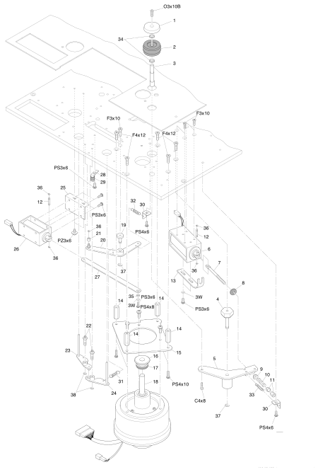 ⤢ zoomPinch Roller Assembly: KP-4X / Capstan Assembly: KC-41H / Shifter Assembly: KR-4W: isometric exploded view of the combined pinch-roller, capstan and shifter mechanism, showing the pinch roller arm assembly and its solenoid, the capstan motor, the shifter link assembly with its lifter arms A and B and shifter solenoid, with each part numbered 1-38 and its fastener code (O3x10B, F3x10, F4x12, PS3x6, PS4x6, PS4x8, PS4x10, PZ3x6, C4x8, and washer code 3W) on a leader line.
| No. | Description | Parts No. |
|---|---|---|
| 1 | Cap. Pinch Roller | KP0C034 |
| 2 | Pinch Roller Assembly | KP-4S-B |
| 3 | Shaft, Pinch Roller | KP0B060 |
| 4 | Shaft, Arm | KP4L001 |
| 5 | PinchRoller Arm Assembly | KP-4X-A |
| 6 | Solenoid | GP1B12 |
| 7 | Screw, Adjustment | KZ6A113 |
| 8 | Damper | PZ1C021 |
| 9 | Washer Spherical | KP0G004 |
| 10 | Spring | GS2163 |
| 11 | Nut, Dubble | F517-4 |
| 12 | Pin, Solenoid | KZ5A003 |
| 13 | Stopper, Solenoid | KZ2A016 |
| 14 | Stud | KZ9I250A |
| 15 | Bracket, Motor | KC4H001 |
| 16 | Cap, Dust | KC0B029 |
| 17 | Ring | PZ1C130 |
| 18 | Motor, Capstan | MR-1L |
| 19 | Shaft, Link Arm | KR4W005 |
| 20 | Shifter Link Assembly | KR-4W-A |
| 21 | Collar | KZ7C109 |
| 22 | Shaft, Arm | KR4B001 |
| 23 | Arm A, Lifter | KR0B005 |
| 24 | Arm B, Lifter | KR0B006 |
| 25 | Bracket, Shifter Solenoid | KR4W007 |
| 26 | Solenoid | GP1A09 |
| 27 | Arm, Link | KR4W004 |
| 28 | Angle | KZ3A042 |
| 29 | Pipe, Rubber | PZ1C174 |
| 30 | Hook | KZ3A167 |
| 31 | Spring | GS1185 |
| 32 | Spring | GS1028-A |
| 33 | Spring | GS1149 |
| 34 | Washer, Polyslider | F524060 |
| 35 | Stud | KZ7A823 |
| 36 | Ring, E type | F74TE09 |
| 37 | Ring, E type | F74TE20 |
| 38 | Ring, E type | F74TE15 |
Tension Arm Assembly: KA-4X/KA-4Y↑ TOP
Impedance Roller Assembly: KI-4T↑ TOP
Timer Assembly: ZA-95G↑ TOP
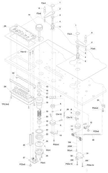 ⤢ zoomTension Arm Assembly: KA-4X/KA-4Y / Impedance Roller Assembly: KI-4T / Timer Assembly: ZA-95G: isometric exploded view of the combined tension-arm, impedance-roller and timer mechanism, showing the tension arm and its switch actuator and magnet assembly, the impedance roller sub-assembly (KI-4J-A), the roller tacho PCB assembly and tacho disk, and the timer display assembly with its two rows of buttons and its printed panel legend (SET, ZERO, SEARCH with H/M/S and 1/2/3, REPEAT, CLR, TAPE SPEED with L/H, TIME-IPS-%), with each part numbered 1-34 and its fastener code (F2x4, F3x6, F3x12, TP2.6x6, C3x10, PS3x6, PS4x6, PZ3x6, P2x5, PS3x15, and washer codes 3W/3SW/B3x4/S3x4) on a leader line.
| No. | Description | Parts No. | Notes |
|---|---|---|---|
| 1 | Cap, Arm | KA0C005 | |
| 2 | Arm, Tension | KA0A017A | |
| 3 | Shaft, Arm | KA4J001 | |
| 4 | Washer, Polyslider | F524-5 | |
| 5 | Holder, Arm | KA0B008 | |
| 6 | Guide, Tape | KG4D007 | |
| 7 | Hook, Spring | KZ3A024 | |
| 8 | Nut | KZ6D004 | |
| 9 | Hook A, Spring | KA0E017 | |
| 10 | Arm, Stopper | KA4X001 | |
| 11 | Hook B, Spring | KA0E005 | |
| 12 | Switch Actuator Assembly | KA-4K-B | |
| 13 | Magnet Assembly | KA-4K-C | |
| 14 | Roller Assembly | KI-4J-B | Impedance Roller Sub Assembly KI-4J-A |
| 15 | Collar | KZ7C057 | |
| 16 | Bearing | BA1Z022 | |
| 17 | Ring | F7017 | |
| 18 | Holder | KI0B014 | |
| 19 | Spring | GS2077 | |
| 20 | Washer | KZ6C057 | |
| 21 | Ring, Shaft | F7206 | |
| 22 | Washer | KI0H024 | |
| 23 | Nut, Holder | KI0H025 | |
| 24 | Boss | KI4T001 | |
| 25 | Disk, Tacho | SR3Z033 | |
| 26 | Stud | KZ9H480C | |
| 27 | ROLLER TACHO PCB Assembly | PB-4HCA | |
| 28 | Timer Display Assembly | ZA-95G | |
| 29 | Spring | GS1025 | |
| 30 | Spring | GS1048 | |
| 31 | Switch, Micro | WH51027 | |
| 32 | Hook, Spring | KZ3A023 | |
| 33 | Hook | KZ3A167 | |
| 34 | Bracket | KZ2A165 |
Control Assembly: CB-23U↑ TOP
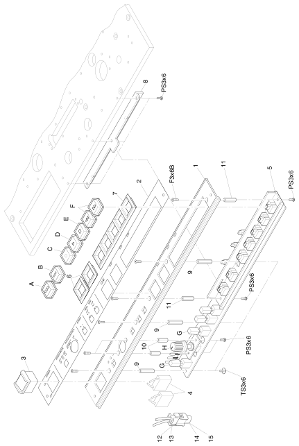 ⤢ zoomControl Assembly: CB-23U: isometric exploded view of the MKIV-2 control panel, showing the control panel and its overlay sheet, the power switch, the transport control switch PCB assembly with its eight buttons (CUE, EDIT, RECORD, PLAY, STOP, F.FWD/RWD, the selector switch and the pitch-control knob and cap, lettered A-H), the switch escutcheons and the plug/receptacle connector housings, plus the printed front-panel legend below the buttons (POWER ON/OFF, SPEED MODE EXT/FIX/VARI, PITCH CONTROL UP/DOWN, SPEED L/H, REEL SIZE SUP S/L, T.UP S/L), with numbered items 1-15, lettered items A-H and their fastener codes (PS3x6, TS3x6, F3x6B) on leader lines.
| No. | Description | Parts No. |
|---|---|---|
| 1 | Panel, Control | CB23U01 |
| 2 | Sheet, Control Panel | CB23U02 |
| 3 | Switch, Power | WH42062 |
| 4 | Capacitor, Spark Killer | CZ20001W |
| 5 | TRANSPORT CONTROL SWITCH PCB Assembly | PB-7UZA |
| A | Button, CUE | KN2145 |
| B | Button, EDIT | KN2147 |
| C | Button,RECORD | KN2144 |
| D | Button, PLAY | KN2142 |
| E | Button, STOP | KN2141 |
| F | Button, F.FWD, RWD | KN2143 |
| G | Switch, Selector | KN2184 |
| H | Knob | KN1108 |
| H | Cap, Knob | KN1099 |
| 6 | Escutcheon, Switch | PZ4A026 |
| 7 | Escutcheon, Switch | PZ4A027 |
| 8 | Angle | T006704 |
| 9 | Stud | KZ7B160 |
| 10 | Stud | KZ7B158 |
| 11 | Stud | KZ7B159 |
| 12 | Connector Housing, Plug | CN402029 |
| 13 | Connector Contact, Plug | CN7B-041 |
| 14 | Connector Housing, Receptacle | CN402030 |
| 15 | Connector Contact, Receptacle | CN7B-042 |
Amplifier Assembly: A1221↑ TOP
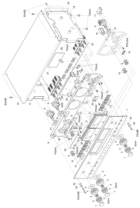 ⤢ zoomAmplifier Assembly: A1221: isometric exploded view of the MKIV-2 record/reproduce amplifier module, showing the amp trim panel assembly with its knobs and VU meter, the amp top panel, the left and right amp side assemblies, the amp connector panel assembly and cover, carrying the REC/REP AMP, four lettered LED, REC EQ and VU meter amp PCB assemblies, with each part numbered 1-31 and its fastener code (S3x4, O3x25B, O3x8B, B3x6B, TS3x6, PS3x6, 1PS2.6x6, and washer codes 3N/3SW) on a leader line.
| No. | Description | Parts No. |
|---|---|---|
| 1 | Cap, Knob | KN1102 |
| 2 | Knob | KN1100A |
| 3 | Collar | KZ7C111 |
| 4 | Knob | KZ1063B |
| 5 | Spacer | KZ6C017 |
| 6 | Potentiometer | RV224005 |
| 7 | Amp. Trim Panel Assembly | A1220-A |
| 8 | Panel, Amp. Top | A1220-B |
| 9 | VU Meter | ME11005 |
| 10 | Jack, Phone | CN602144 |
| 11 | Switch | WH340013 |
| 12 | Button | KN2095 |
| 13 | Button | KN2094 |
| 14 | Button | KN2093 |
| 15 | Blind | PZ1B012 |
| 16 | Blind | PZ1B010 |
| 17 | Amp. Side L Assembly | A1177-C |
| 18 | Amp. Side R Assembly | A1177-B |
| 19 | Cover, Amp. | A117705 |
| 20 | Amp. Connector Panel Assembly | A117701 |
| 21 | Shield, Illumination | PZ1B013 |
| 22 | REC/REP AMP. PCB Assembly | PB-1GYB |
| 23 | LED (D) PCB Assembly | PB-83AB |
| 24 | LED (F) PCB Assembly | PB-83BB |
| 25 | LED (E) PCB Assembly | PB-83CAA |
| 26 | LED (C) PCB Assembly | PB-81JB |
| 27 | REC EQ PCB Assembly | PB-81QA |
| 28 | VU METER AMP. PCB Assembly | PB-16DB |
| 29 | Washer, Trim | KZ6C051 |
| 30 | Washer | KZ6C011 |
| 31 | Spacer | A122004 |
Amp. Connector Assembly: A1221↑ TOP
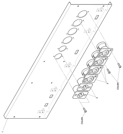 ⤢ zoomAmp. Connector Assembly: A1221: isometric exploded view of the MKIV-2 amplifier connector panel, showing the amp connector panel assembly and the row of five XL-type male and female audio connectors, with each part numbered 1-3 and its fastener code (O3x8N) on a leader line, and the four PUSH tabs printed on the XL-type connectors.
| No. | Description | Parts No. |
|---|---|---|
| 1 | Amp. Connector Panel Assembly | A117701 |
| 2 | Connector, XL type, Male | CN103195 |
| 3 | Connector, XL type, Female | CN103194 |
Connector Panel Assembly: CB-794↑ TOP
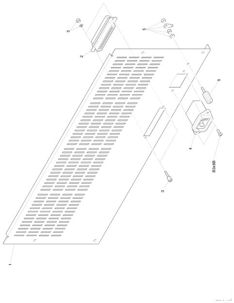 ⤢ zoomConnector Panel Assembly: CB-794: isometric exploded view of the MKIV-2 rear connector panel, showing the connector panel with its ventilation slots, the D-sub 37-pin connector, AC inlet and ground terminal, with each part numbered 1-5 and its fastener code (B3x8B) on a leader line.
| No. | Description | Parts No. |
|---|---|---|
| 1 | Panel, Connector | CN7B-212 |
| 2 | Connector, D sub 37pin | CN237326 |
| 3 | Screw, Lock | CN7B-212 |
| 4 | AC Inlet | CN603012 |
| 5 | Terminal, Ground | CN901040 |