Operation manual (OIM-1005E) · Part 2 · scan pages 18-26
Installation
This section of the manual provides information about unpacking and inspection, locations and environment, mounting configurations, and power and signal connections.
II-1. UNPACKING AND INSPECTION↑ TOP
The MX-5050 Series system is shipped from the factory in individual cardboard packing cases. Upon receipt, examine the case for any signs of damage. Unpack the equipment carefully and inspect for any signs of damage. Use great care when unpacking unmounted equipment, and removing packing materials, to prevent damage to critical components such as the capstan, head assembly, and tension arms.
Referring to Table I-4 and Table I-5 (as applicable), verify that all items have been received. Report any shortage or damage to the carrier and any your local Otari dealer. Save the packing case for possible shipment of the equipment to another location or for the case of re-shipment. Other packaging may cause the damage during transportation and will void the warranty.
Regarding the repacking method, please refer to the illustration which is attached on the flap of the individual box.
II-2. LOCATION AND ENVIRONMENT↑ TOP
The area chosen for operation should be adequately ventilated and dust free. Since recording is by an electromagnetic process, it is possible that strong electromagnetic fields may affect the system adversely. Common sources of interference are fluctuation loads on nearby high-voltage lines, heavy duty transformers, and transmitting equipment.
It is recommended that the equipment be used in an environment where the surrounding temperature does not exceed limits of 40° to 104°F (5° to 40°C), with the relative humidity between 20 to 80%. Allow at least 4-inches clearance behind the rear-panel ventilation grille.
II-3. MOUNTING CONFIGURATIONS↑ TOP
The MX-5050 Series can be mounted vertically or horizontally and in a common 19-inch rack using an optional rack mount adaptor kit (Table I-5). The MX-5050 in a rack mount adaptor requires 19¼ inches of rack space. Maximum cooling efficiency is obtained when the unit is mounted vertically.
Equipment dimensions of the unmounted version of the MX-5050 Series are shown in Fig. II-1.
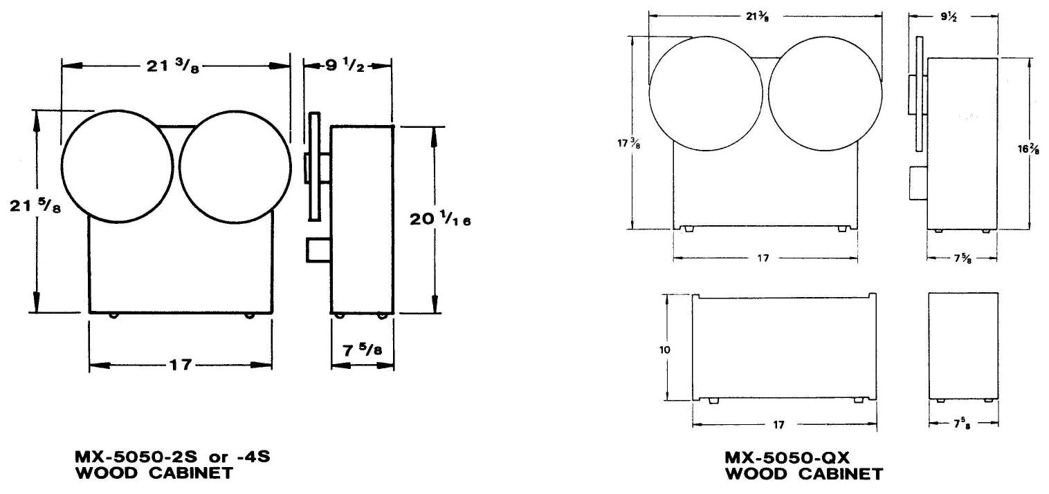 ⤢ zoomLine-drawing dimension diagrams for the MX-5050-2S or -4S wood cabinet and the MX-5050-QX wood cabinet, each giving width, depth, and height measurements from front and side views
Fig. II-1 Equipment Dimensions
II-4. POWER AND SIGNAL CONNECTIONS↑ TOP
All power and signal connections are made to the connector panel at the rear of the MX-5050. Table II-2 shows the function of each connector and component on the rear panel.
Table II-1. Rear Connector Panel
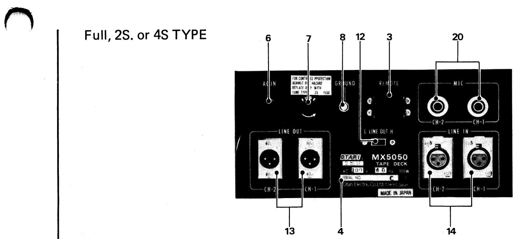 ⤢ zoomRear connector panel of an MX-5050 Full, 2S, or 4S type recorder, photographed with numbered leader lines 1 through 20 pointing to each connector, switch, and adjustment point
Full, 2S. or 4S TYPE
| Index No. | Name | Function |
|---|---|---|
| 1 | REPRODUCE HEAD Connector | Female RB-type connector for reproduce signal, connected with connector cable from amplifier. |
| 2 | RECORD/ERASE HEAD Connector | Female SRC-type connector for record and erase signal, connected with connector cable from amplifier. |
| 3 | REMOTE control connector | Remote control connector for use with optional remote control unit to control modes, record, play, stop, rewind, and fast forward. |
| 4 | Label | Indicates Model Number, production lot number (serial number), power requirements and "Made in Japan". |
| 5 | TO AMPLIFIER Connector | Female QS-type connector to supply power, bias signal and control signal for amplifier. |
| 6 | AC In Cable | Captive three-wire cable for connection to AC power and power ground. |
| 7 | Fuse | Main power fuse. For replacement use 2A fuse, Otari Part No.FS-1-2A. |
| 8 | GROUND Terminal | Auxiliary ground connection for use with equipment not connected to common AC ground. |
| 9 | Reproduce Head Connector Cable | Connected to REPRODUCE connector for reproduce signal. |
| 10 | BIAS TRAP Adjustment Screws | Used to adjust bias trap for reproduce. Precaution: Do not touch these screws. Limited only for adjustment in case of parts replacement or calibration. |
| 11 | REP. EQ. Adjustment Screws | Used to adjust frequency characteristics for reproduce equalizer. Precaution: Do not touch these screws. Limited only for adjustment in case of parts replacement or calibration. |
| 12 | LINE OUTPUT LEVEL selector switch | Two-position output level switch to select +4 dBm or −10 dBm output standard reference level (SRL). |
| 13 | LINE OUTPUT Connector | Male XLR-type connector for unbalanced line output impedance, 600 ohms. For 600 ohms balanced line output, use optional transformer (Otari Part No.ET-31-182). Note: Line Output transformers, 600 ohms, balanced are standard for MX-5050-2SHT. |
| 14 | LINE INPUT Connector | Female XLR-type connector for unbalanced line input impedance, 50,000 ohms. For 600 ohm balanced input, use optional matching transformater (Otari Part No.ET-21-181). |
| 15 | BIAS TRAP Adjustment Screws | Used to adjust bias trap for SEL/REP. Precaution: Do not touch these screws. Limited only for adjustment in case of parts replacement or calibration. |
| 16 | SEL. REP. LEVEL Adjustment Screws | Used to adjust SEL/REP level. Precaution: Do not touch these screws. Limited only for adjustment in case of parts replacement or calibration. |
| 17 | Record MONITOR Level ADJ.stment screws | Used to adjust record monitor level. Precaution: Do not touch these screws. Limited only for adjustment in case of parts replacement or calibration. |
| 18 | TO DECK Connector | Male QS-type Connector to supply power, bias and control signal for amplifier. |
| 19 | Record/Erase Head Connector Cable | Connected to RECORD/ERASE HEAD for record and erase signal. |
| 20 | MICROPHONE Input Jack | Standard 2-conductor phone jack for microphone: −70 dBm, unbalanced, 50,000 ohms (high impedance). |
II-4-(1) AC POWER CONNECTION↑ TOP
The MX-5050 Series is factory set to operate at the line voltage and frequency indicated on the packing case and on the rear connector panel of equipment. AC power is connected by means of a captive three-wire power cable which also provides a common ground connection. If a two-wire receptacle is used with an adaptor, be sure the adaptor is properly grounded.
If some other change of line voltage and frequency is desired to accomodate a different power requirement, please contact your nearest dealer or Otari.
II-4-(2) SIGNAL CONNECTIONS↑ TOP
On Model QX: The reproduce head connectors are four-conductor male RB-type connector, connected directly to the rear of amplifier. The record and erase head connectors are ten-conductor male SRC-type connector, connected directly to the rear of amplifier. The amplifier to transport connector is QS-type connector.
On all models: The microphone inputconnectors are standard two-conductor phone jacks. The line input (female) and line output (male) connectors are XLR-type connectors. The mating connectors (not supplied) may be wired for balanced or unbalanced input as follows:
LINE INPUT CONNECTOR WIRING:
For balanced input, wire male XLR connector as follows:
- Connect signal leads of two-conductor shielded cable to pin 3 (high) and pin 2 (low) of connector.
- Connect cable shield to pin 1.
For unbalanced input using two-conductor shielded cable, wier female XLR-connector as follows:
- Connect signal leads of cable to pin 3 (high) and pin 2 (low) of connector.
- Connect cable shield to pin 1 of connector.
- Connect a jumper from pin 1 to pin 2 of connector.
For unbalanced input using single conductor shielded cable, wire male XLR connector as follows:
- Connect center conductor of single-conductor shielded cable to pin 3 of connector.
- Connect cable shield to pins 2 and 1.
LINE OUTPUT CONNECTOR WIRING:
For balanced output, wire female XLR connector as follows:
- Connect signal leads of two-conductor shielded cable to pin 3 (high) and pin 2 (low) of connector.
- Connect cable shield to pin 1.
For unbalanced output using two-conductor shielded cable, wire female XLR connector as follows:
- Connect signal leads of cable to pin 3 (high) and pin 2 (low) of connector.
- Connect cable shield to pin 1 of connector.
- Connect a jumper from pin 1 to pin 2 of connector.
For unbalanced output using single-conductor shielded cable, wire female XLR type connector as follows:
- Connect center conductor cable to pin 3 of connector.
- Connect cable shield to pin 2 of connector.
- Connect a jumper between pins 1 and 2 of connector.