QXD Maintenance Manual — Digital Edition · Part 1 · scan pages 7-12
General Information
This manual is a maintenance supplement to the MX-5050 Series Models 2SD₂, QXD, ½QXD and 8SD Instruction Manual, Catalog No. OIM-1004E, and provides detailed maintenance information. This manual is intended for use by qualified maintenance or service personnel only. Prior to using this manual, it is suggested that the user become familiar with the information contained in the basic manual.
1-1 TEST AND MAINTENANCE EQUIPMENT REQUIREMENTS↑ TOP
All maintenance, electronic, and mechanical test equipment required during maintenance, alignment, and adjustment of the recorder is listed in Table 1-1. In addition, recommended maintenance periods are shown by accumulative hours of usage and/or elapsed period of time, whichever occurs first. Equivalent equipment can be substituted for the equipment suggested in the table.
Table 1-1. Test and Maintenance Equipment
| EQUIPMENT TYPE | SUGGESTED MODEL | USED FOR | PERIOD |
|---|---|---|---|
| Head cleaner | Ampex 087-007 | Cleaning heads and guides | 8 hours |
| Isopropyl or denatured alcohol | Any | Cleaning capstan pinch-roller | 8 hours |
| Q tips | Any | Cleaning heads and guides | 8 hours |
| Head demagnetizer | Ampex 4010820 | Demagnetizing heads and guides | 8 hours |
| Lubricating oil | Ampex 087-579 or Mobile DTE Medium | Oiling of capstan motor and pinch roller bearings | 1,000 hours or 6 months |
| Spring scales 0-16 oz, 0-32 oz and 0-10 lbs | Any | Mechanical adjustments | 1,000 hours or 6 months |
| Vacuum cleaner and brushes | Any | General cleaning | 1 month |
| Standard alignment test tapes | Refer to Table 1-2 and 1-3. | Reproduce amplifier alignment | 150 hours or 1 month |
| Audio oscillator | Hewlett Packard H20-200CD | Overall frequency response and signal-to-noise measurement | 150 hours or 1 month |
| AC Voltmeter (VTVM) | Hewlett Packard 400L or 400 FL | Same as above | Same as above |
| Bandpass filter | See text | Same as above | Same as above |
| Flutter bridge | Data Measurement Corp. 8100 | Flutter and wow measurement | Same as above |
| Wave analyzer | Hewlett Packard 3590A or 310A | Distortion and crosstalk measurement | Same as above |
| Test cables | See text | ||
| Technicians tools | |||
| Stroboscope | General Radio 1531-AB | Mechanical adjustments | 1,000 hours or 6 months |
| Volt-ohm meter | 20,000 ohms/volt any brand | Test and adjustments | — |
| Allen wrenches | Metric | ||
| ASA Noise Filter | See text and Fig. 3-1. | Signal-to-noise ratio measurement | 150 hours or 1 month |
Table 1-2. Flutter Test Tapes
| TAPE WIDTH (INCHES) | SPEED (IN/S) | FREQUENCY (HZ) | AMPEX CATALOG NO. |
|---|---|---|---|
| 1/4 | 3¾ | 3000 | 01-31336-01 |
| 1/4 | 7½ | 3000 | 01-31326-01 |
| 1/4 | 15 | 3000 | 01-31316-01 |
| 1/2 | 7½ | 3000 | 01-31326-05 |
| 1/2 | 15 | 3000 | 01-31316-05 |
Table 1-3. Alignment Test Tape
| TAPE WIDTH (INCHES) | SPEED (IN/S) | EQUALIZATION (TIME CONSTANTS) | STANDARD | TRACKS | AMPEX CATALOG NO. |
|---|---|---|---|---|---|
| 1/4 | 3-3/4 | 90 µs & 3180 µs | NAB | Full | 4690037-01 |
| 1/4 | 7-1/2 | 50 µs & 3180 µs | NAB | Full | 01-31321-01 |
| 1/4 | 7-1/2 | 50 µs & 3180 µs | NAB | 1 & 3 | 01-31321-04 |
| 1/4 | 7-1/2 | 70 µs & ∞ | IEC | Full | 4690014-01 |
| 1/4 | 15 | 50 µs & 3180 µs | NAB | Full | 01-31311-01 |
| 1/4 | 15 | 35 µs & ∞ | IEC | Full | 01-31313-01 |
| 1/2 | 7-1/2 | 50 µs & 3180 µs | NAB | Full | 01-31321-05 |
| 1/2 | 7-1/2 | 70 µs & ∞ | IEC | Full | 4690015-01 |
| 1/2 | 15 | 50 µs & 3180 µs | NAB | Full | 01-31311-05 |
| 1/2 | 15 | 35 µs & ∞ | IEC | Full | 01-31313-05 |
1-2 ROUTINE MAINTENANCE↑ TOP
It is important that routine maintenance be performed at the recommended intervals. External cleaning and demagetization procedures should be performed after each eight hours of operation, and the interior of the transport should be cleaned once a month. The lubrication procedure should be performed after 1,000 hours of operation or after 6 months, whichever comes first.
1-2-(1) CLEANING↑ TOP
Oxide particles from the magnetic tape tend to collect on components in the tape path and degrade performance of the recorder. To clean the head assembly, proceed as follows:
- Lift the head cover as shown in Fig. 1-1.
— CAUTION —
WHEN CLEANING THE HEADS, USE ONLY THE RECOMMENDED SOLVENT (HEAD CLEANER) TO AVOID DAMAGING THE HEADS. KEEP THE HEAD CLEANER OFF PLASTIC FINISHES AND THE CAPSTAN PINCH ROLLER. DO NOT USE METAL TOOLS THAT CAN SCRATCH THE HEADS.
- Clean each head stack thoroughly with a cotton-tipped applicator (Q tip) dampened with head cleaner.
- Use isopropyl alcohol to clean all tape-guiding components, the capstan shaft, and the capstan pinch roller.
— CAUTION —
DO NOT USE HEAD CLEANER ON THE CAPSTAN PINCH ROLLER AS DAMAGE WILL RESULT AND TAPE WILL SLIP.
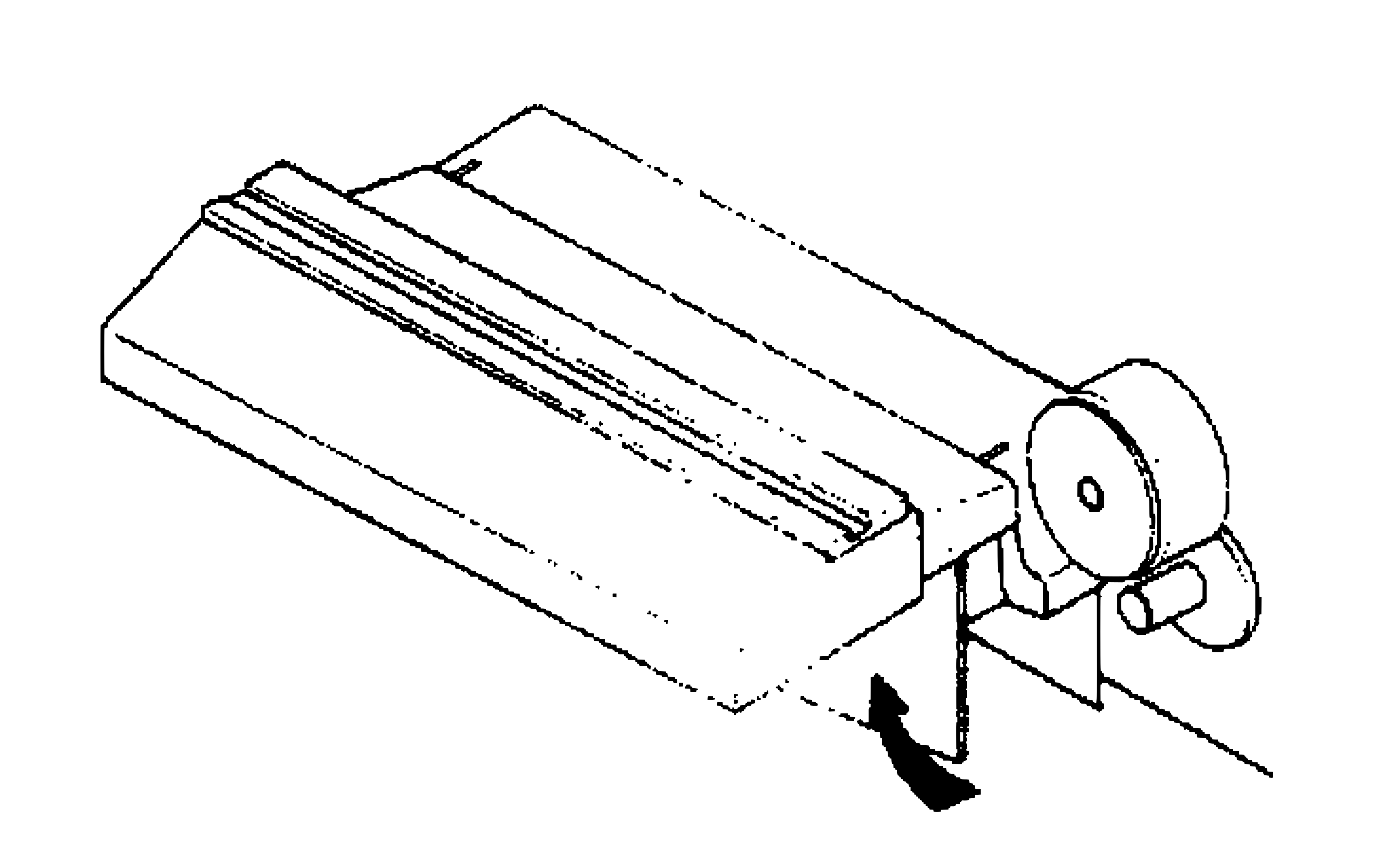 ⤢ zoomFig. 1-1 Lifting Head Cover: an exploded isometric view of the head cover's hinged panel lifted up and away from the head block along two parallel score lines, an arrow marking the lift direction, with the capstan motor's flywheel and knob visible to the right
Fig. 1-1 Lifting Head Cover
- Pull Down rear cover of recorder (4 screws).
- Use a vacuum cleaner and a small brush to remove all dust or contamination from the interior of the transport. If necessary lightly moisten brush with isopropyl alcohol to clean parts.
- Reinstall rear cover.
1-2-(2) DEMAGNETIZING↑ TOP
The heads and tape guiding components in the tape path should be demagnetized after each eight hours of operation. These components can acquire permanent magnetization that increases signal noise and distortion and partially erase high frequencies on recorded tape. Use a hand-held head demagnetizer to demagnetize all components in the tape path as follows:
- Turn equipment power off and remove any recorded tape near the transport (tape could be partially erased by the demagnetizer).
- Lift head cover as shown in Figure 1-1.
- Cover the demagnetizer tips with adhesive tape to prevent scratching head stacks.
- With the demagnetizer held away from the transport, connect demagnetizer to power source.
- Move the demagnetizer tips slowly close to the head, lightly touch the demagnetizer tips to the face of one head stack and slowly move the tips up and down the stack several times. Then slowly withdraw the demagnetizer as shown in Fig. 1-2.
- Repeat step 5 for each head stack.
- Repeat the motions of step 5 for each guide and other metallic parts in the tape path.
- Move the demagnetizer slowly away from the transport for at least three feet and then disconnect power from the demagnetizer.
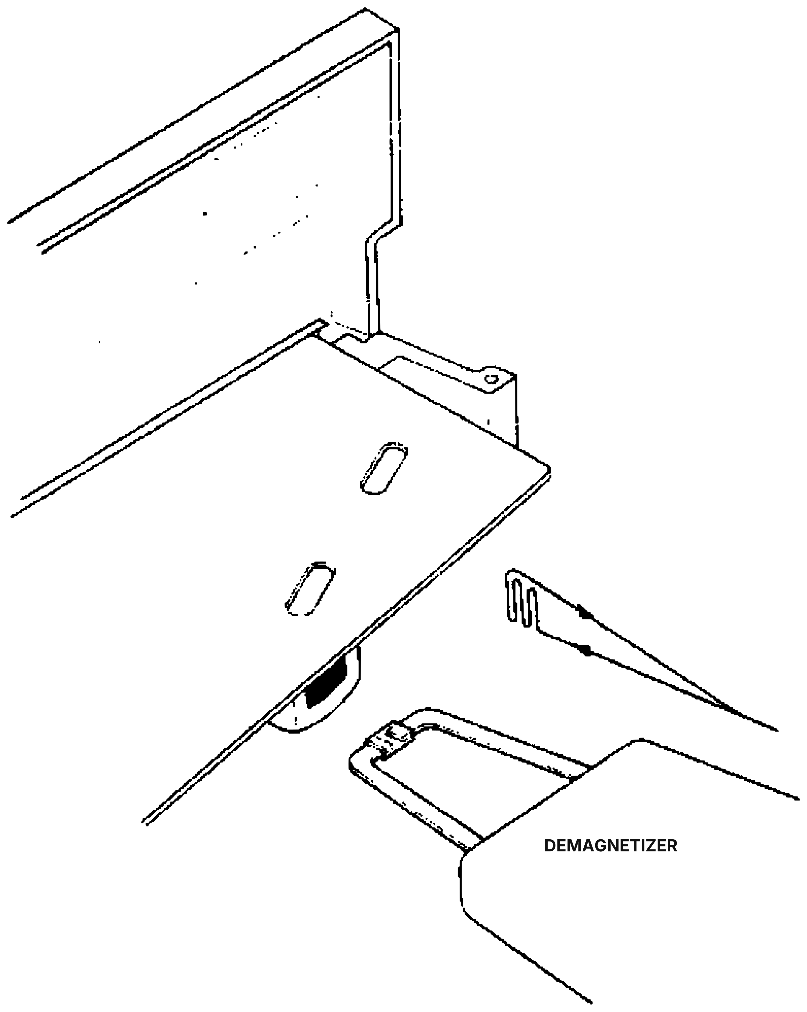 ⤢ zoomFig. 1-2 Demagnetizing: an isometric view of the lifted head cover and its mounting deck, showing two head-stack cutouts and a shaded slot along the deck's front edge, with a hand-held demagnetizer — a looped tool with three tine-like prongs, labeled DEMAGNETIZER — withdrawn from the heads along a diagonal double-headed arrow
Fig. 1-2 Demagnetizing
1-2-(3) LUBRICATION↑ TOP
The only components requiring lubricaiton are the capstan sleeve bearing and the capstan pinch roller bearings. See Fig. 1-3 and proceed as follows:
— CAUTION —
BE CERTAIN TO CLEAN CAPSTAN SHAFT THOROUGHLY. THE LUBRICATING OIL CAN RUIN THE CAPSTAN PINCH ROLLER AND MAGNETIC TAPE. CLEAN THE CAPSTAN AND PINCH ROLLER WITH ISOPROYL ALCOHOL.
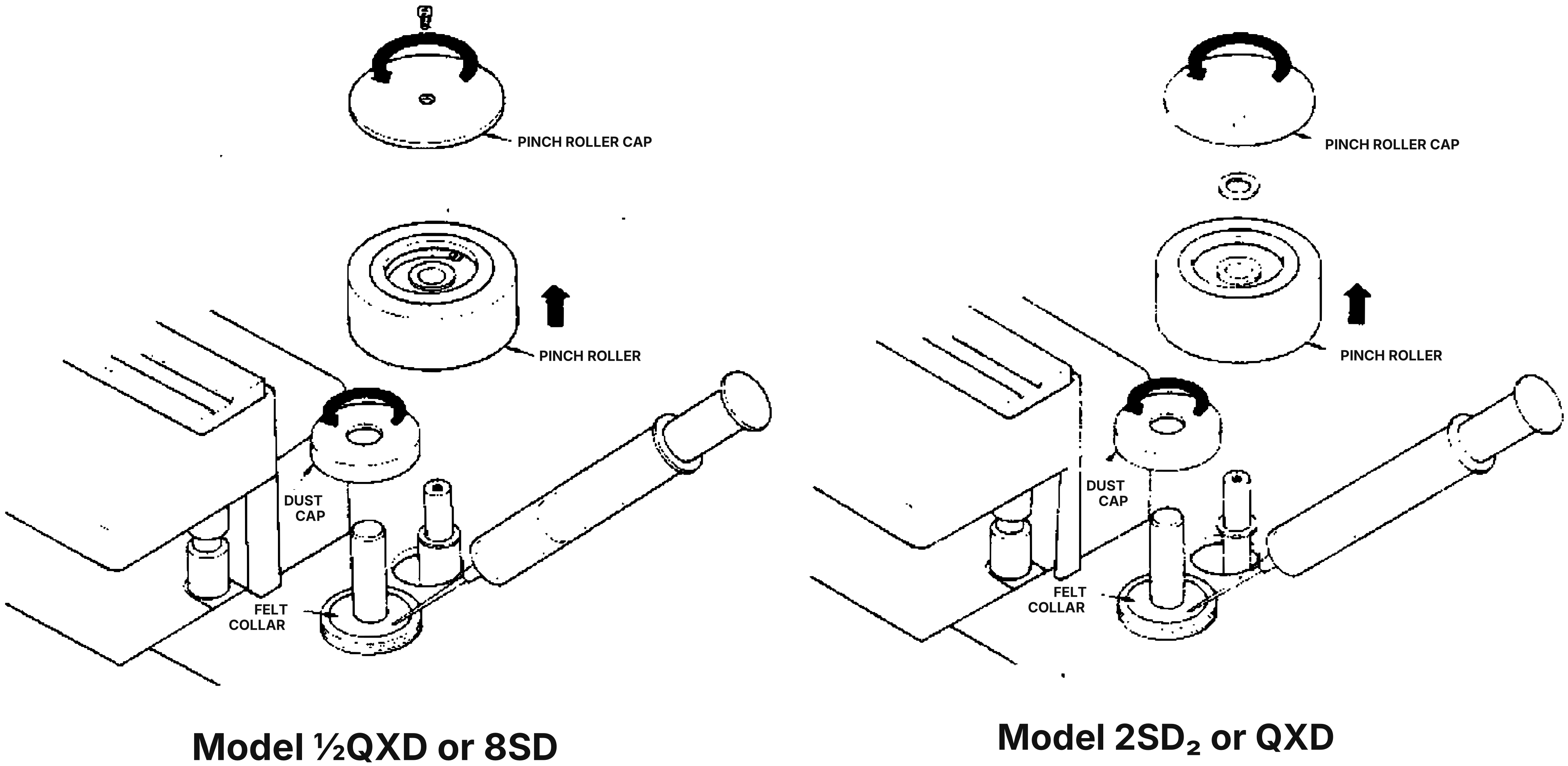 ⤢ zoomFig. 1-3 Lubrication: two side-by-side exploded isometric views of the capstan pinch-roller stack, one for Model ½QXD or 8SD and one for Model 2SD₂ or QXD, each showing the pinch roller cap and pinch roller exploded above the dust cap, felt collar, and capstan shaft, every part labeled with a leader line and each panel captioned with its own model pairing
Fig. 1-3 Lubrication
- Remove pinch roller cap. On Models 2SD₂ or QXD, turn pinch roller cap counterclockwise. On Models ½QXD or 8SD, remove screw on pinch roller cap.
- Remove pinch roller from the pinch roller shaft.
- Remove metal dust cap from the capstan shaft by turning counterclockwise.
- Now the felt collar is visible. Apply 2 or 3 drops of oil onto this felt collar. Please do not over lubricate.
- On Models 2SD₂, QXD, apply a few drops of oil to the pinch roller bearings.
- Wipe off any excess oil and reinstall the dust cap, pinch roller cap as they were.