Service training binder · Part 4 · scan pages 30-40
Basic Technical Concepts for Tape Recorders
8. PART NUMBER FOR OTARI PRODUCTS↑ TOP
OTARI REFERENCE NUMBER↑ TOP
A○○○○○○○○ — 8 digits
- A: Amplifier
- BA: Bearing
- C: Capacitor
- I: IC
- LU: Lamp
- ME: Meter
- PB: PCB
- PN: Diode
- Q: Transistor
- R: Resister
- WH: Switch
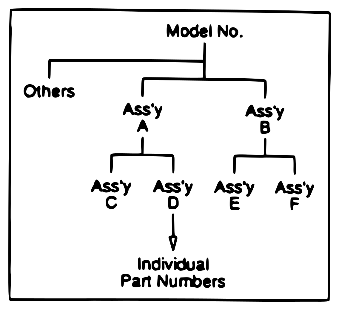 ⤢ zoomModel number to individual part numbers assembly tree
PART NUMBERS FOR PCB↑ TOP
-
PB9○○○○○ : PCB without Components
-
PB-1 (or 4, 6, 7)○○○○ : PCB with Components
-
PB-1○○○○ : Amplifier PCB Assembly
-
PB-4○○○○ : Control PCB Assembly
-
PB-6○○○○ : Power Supply PCB Assembly
-
PB-7○○○○ : Extension PCB Assembly
Ex. PB-1AAB — PCB Type, Renovation Number
9. OTARI CIRCUIT DIAGRAMS↑ TOP
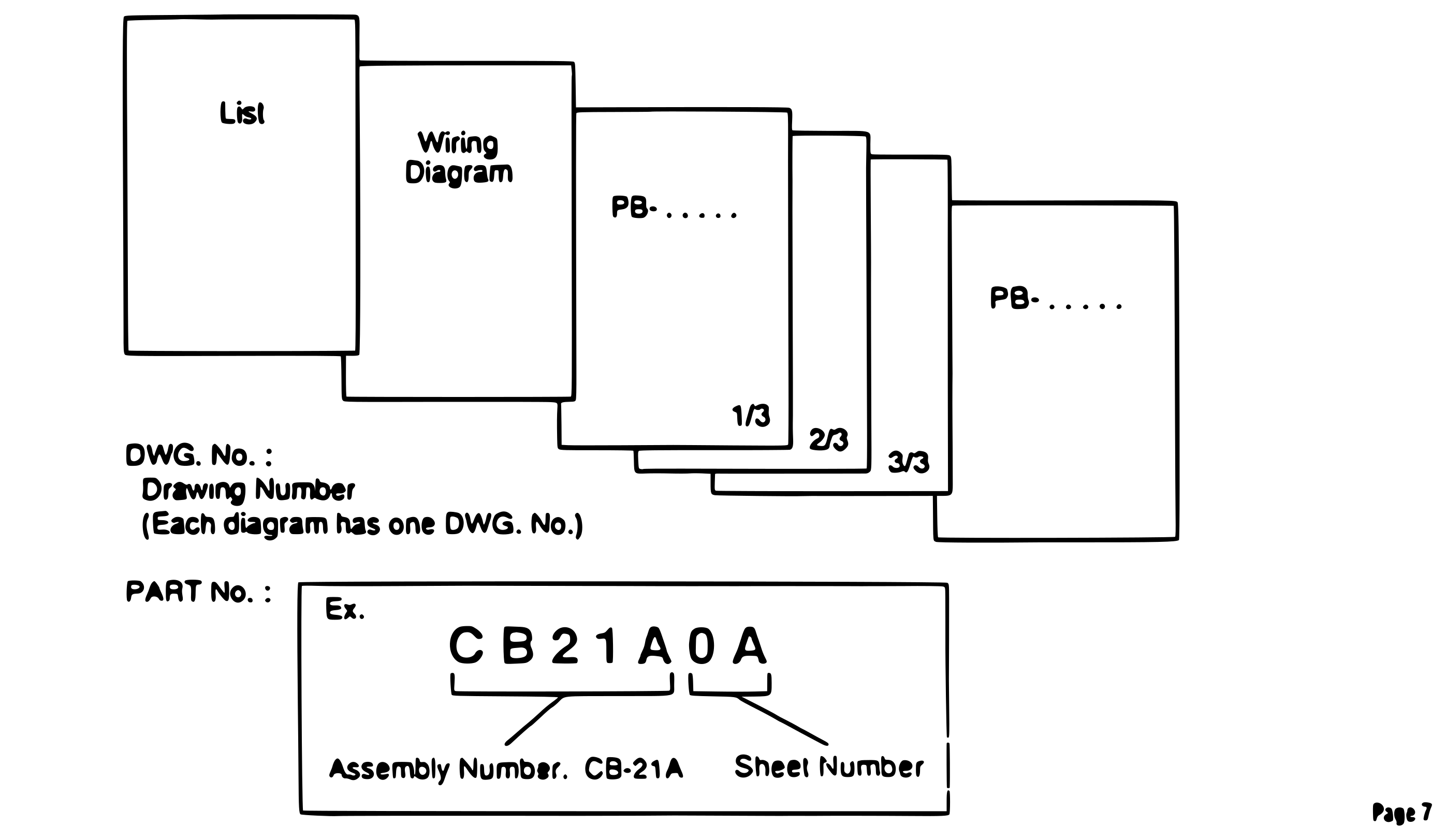 ⤢ zoomHow a set of Otari circuit diagrams is organized — list, wiring diagram, and per-board sheets with drawing and part numbers
BASIC TECHNICAL CONCEPTS FOR TAPE RECORDERS↑ TOP
1. TAPE TENSION↑ TOP
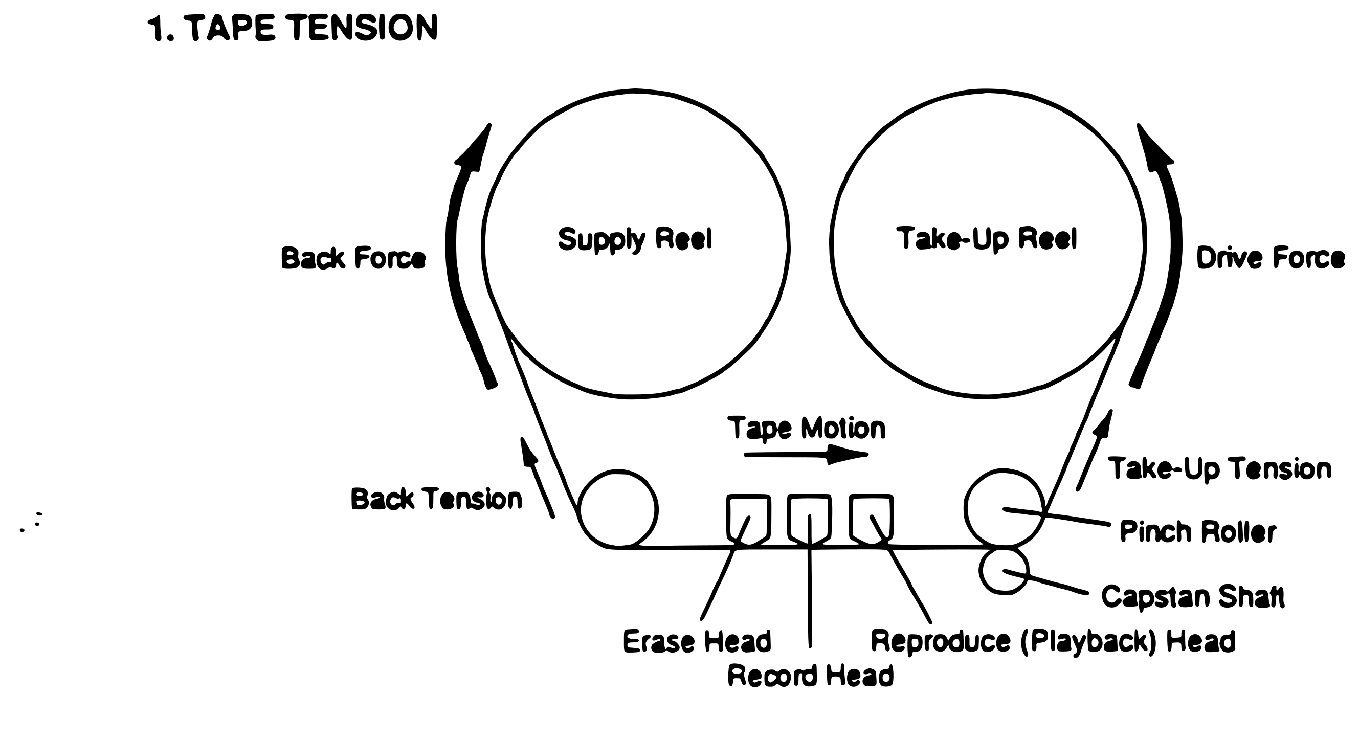 ⤢ zoomTape path with supply and take-up reels, showing back force, back tension, take-up tension, drive force, heads, pinch roller and capstan shaft
2. HEAD CONTACT FORCE↑ TOP
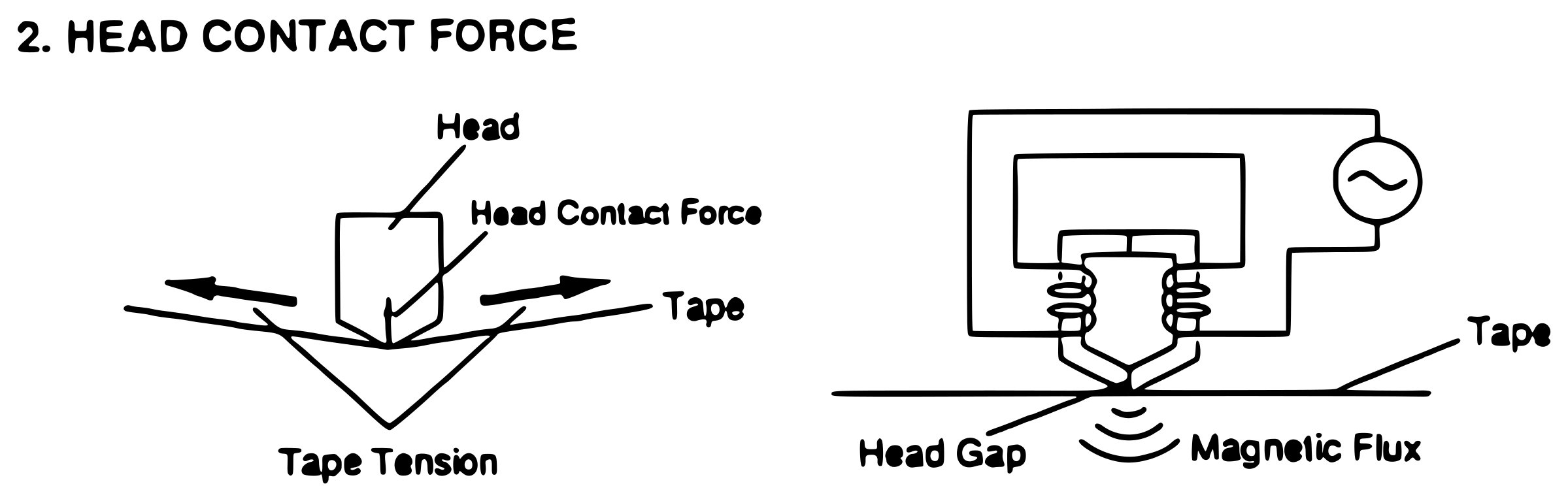 ⤢ zoomHead contact force produced by tape tension, and head gap with magnetic flux linking to the tape
3. HEAD GAP AND DEPTH↑ TOP
 ⤢ zoomHead gap length and depth, output null when wavelength equals gap length, level versus frequency lobes, and the wavelength formula with a worked example
4. TAPE DRIVE SYSTEMS↑ TOP
A. PINCH ROLLER SYSTEM
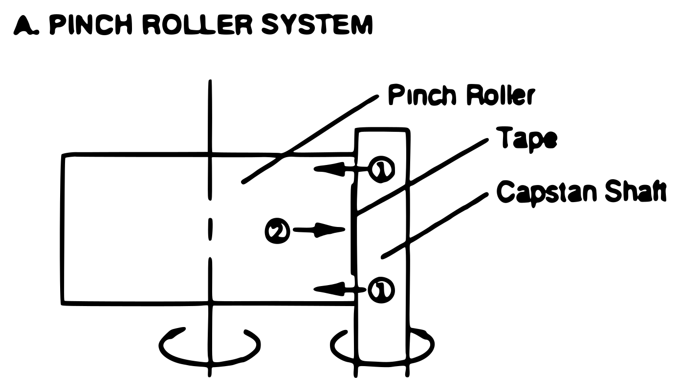 ⤢ zoomPinch roller system with drive force passing from capstan shaft through the pinch roller to the tape
- Drive Force
- ① Capstan Shaft → Pinch Roller
- ② Pinch Roller → Tape
- Since the force is transmitted through elastic material, the tape tension tends to be unstable.
- More Drive Power
B. PINCH ROLLER SYSTEM
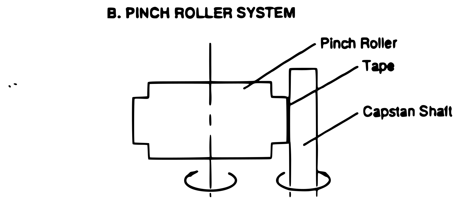 ⤢ zoomPinch roller system with the tape driven directly against the capstan shaft
- Drive Force: Capstan Shaft → Tape → Pinch Roller
- Since the force is not transmitted through elastic material, the tape tension is stable.
- Less Drive Power
- Back Coating Tape
- Tension Servo System → MTR-10, BTR-10, etc.
C. PINCH ROLLERLESS SYSTEM
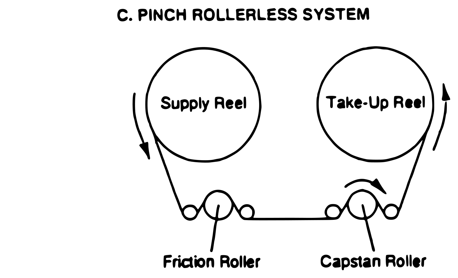 ⤢ zoomPinch rollerless system with friction roller and direct drive capstan roller
- Direct Drive Capstan Roller
- Tension Servo System
- High Accuracy Transport → MTR-90 series, MTR-100A, DTR-900 series
- Same tape path for PLAY, FF, RWD → Quick Response
D. DOUBLE CAPSTAN SYSTEM
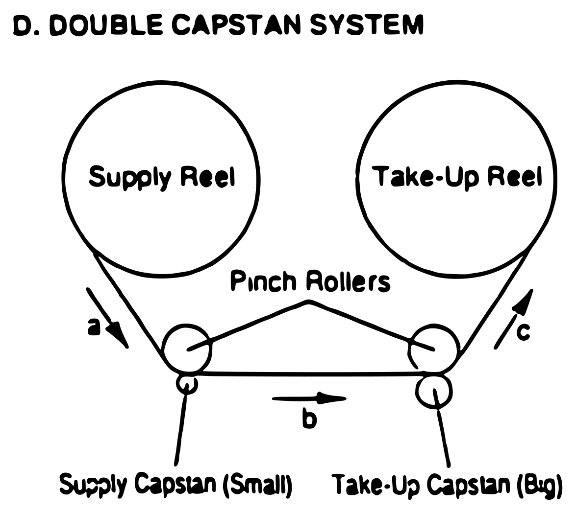 ⤢ zoomDouble capstan system with small supply capstan and big take-up capstan enclosing the head area
- Tension: a > b > c
- Reel Tape Tension does not effect Head Tension. → Stable Head Tension
- Since tension servo technology has progressed, this system is not used much.
Servo Control↑ TOP
1. Reel Motor↑ TOP
- Tension Control
- Open Loop Servo
- Single Direction
- Bidirection
- Closed Loop Servo
- Open Loop Servo
- Winding Speed Control
- Fast Winding
- Controlled Pack (Winding)
2. Capstan Motor↑ TOP
- Speed Control
- PLL (Phase Locked Loop) Servo
- Voltage Servo
- Drive mode
- Pinch Roller type
- Friction Drive type
- Reference
- Internal
- AC Line
- Voltage
- Quartz
- External (for Synchronizer)
- Voltage
- Frequency
- Internal
3. Speed Accuracy↑ TOP
- Absolute Speed Accuracy
- with Tension Servo: +/-0.05%
- without Tension Servo: +/-0.1%
- Speed variation from begining to the end of reel
- with Tension Servo: 0.05%
- without Tension Servo: 0.1%
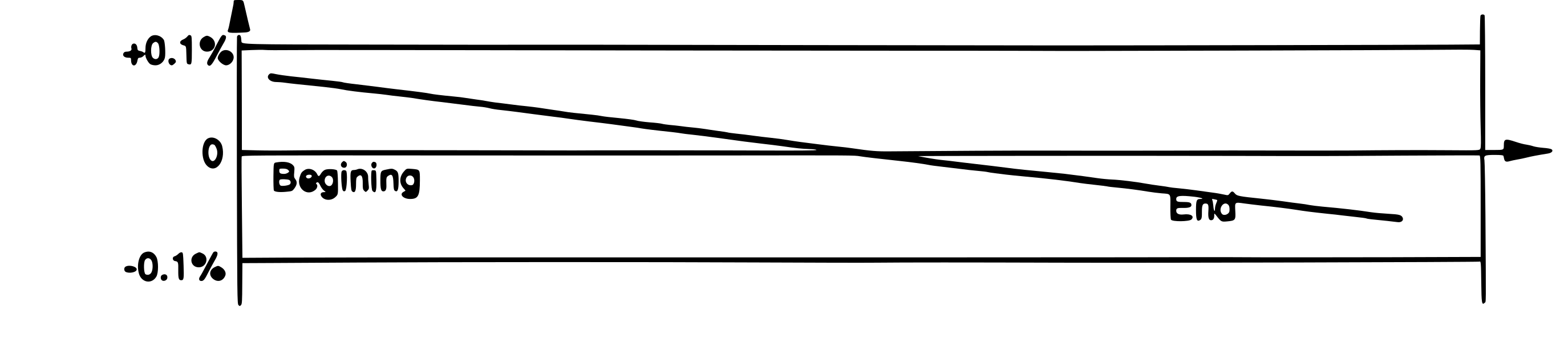 ⤢ zoomTape speed drift from beginning to end of reel
5. RECORDING BIAS↑ TOP
BIAS CHARACTERISTICS↑ TOP
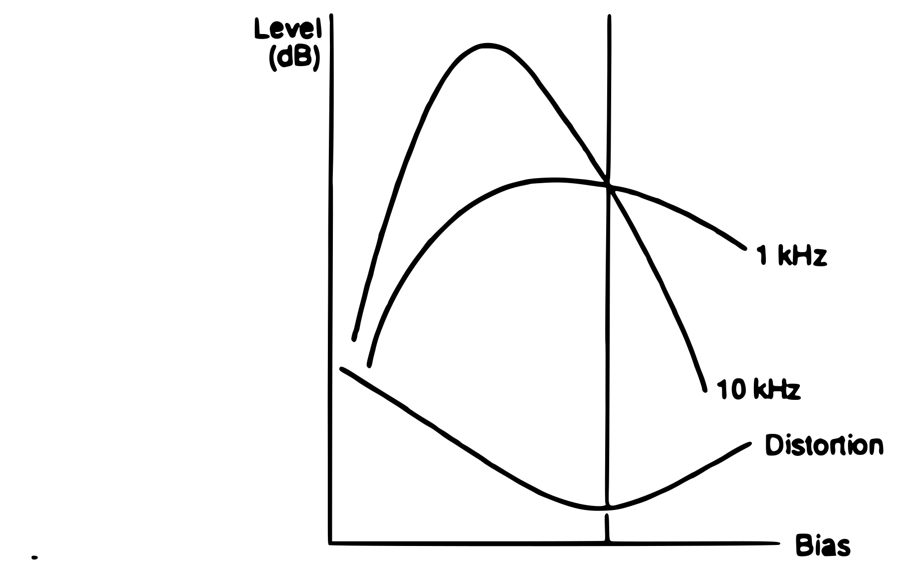 ⤢ zoomBias characteristic — 1 kHz and 10 kHz output level and distortion versus bias
EXAMPLE OF RECOMMENDED OVER BIAS↑ TOP
MX-55N
| Tape Speed (ips) Frequency (Hz) | 3.75 10 k | 7.5 10 k | 15 10 k |
|---|---|---|---|
| AGFA PEM 469 | 8.0 | 5.0 | 3.0 |
| AGFA PEM 468 | 8.0 | 5.5 | 3.5 |
| AMPEX 406/407 | 7.0 | 4.5 | 2.7 |
| AMPEX 456 | 8.0 | 5.5 | 3.0 |
| BASF LGR50P | 7.5 | 5.5 | 3.5 |
| BASF SPR50LH/50LHL | |||
| BASF SM911 | 8.0 | 5.0 | 3.0 |
| SCOTCH 206/207 | 7.0 | 4.5 | 2.7 |
| SCOTCH 226/227 | 8.0 | 4.0 | 3.5 |
| SCOTCH 250 |
(Unit: dB)
 ⤢ zoomDefinition of over bias — output versus bias current with peak bias point Bp and recommended bias point Br
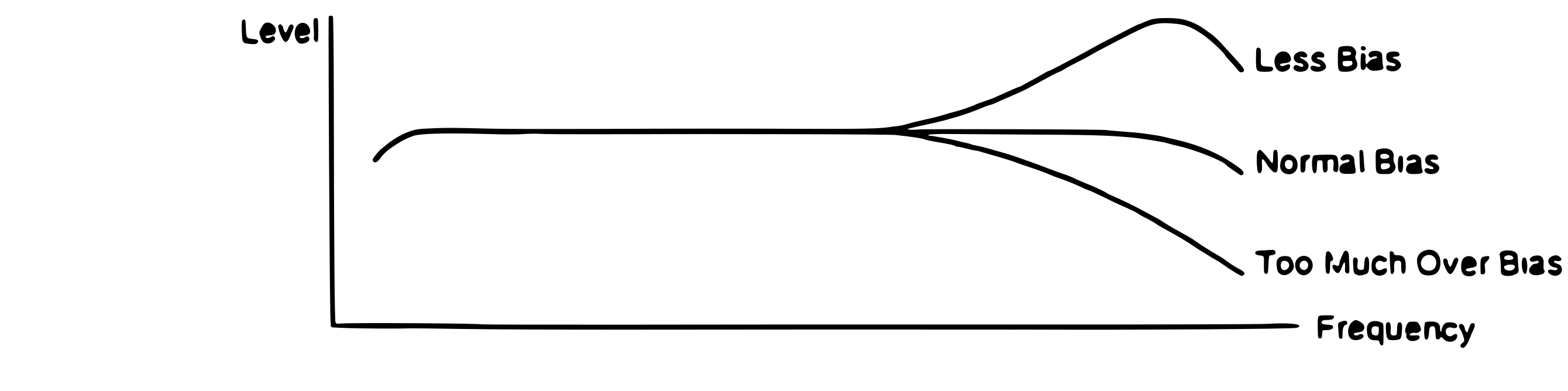 ⤢ zoomFrequency response with less bias, normal bias, and too much over bias
6. Dolby HX pro® HEADROOM EXTENSION SYSTEM↑ TOP
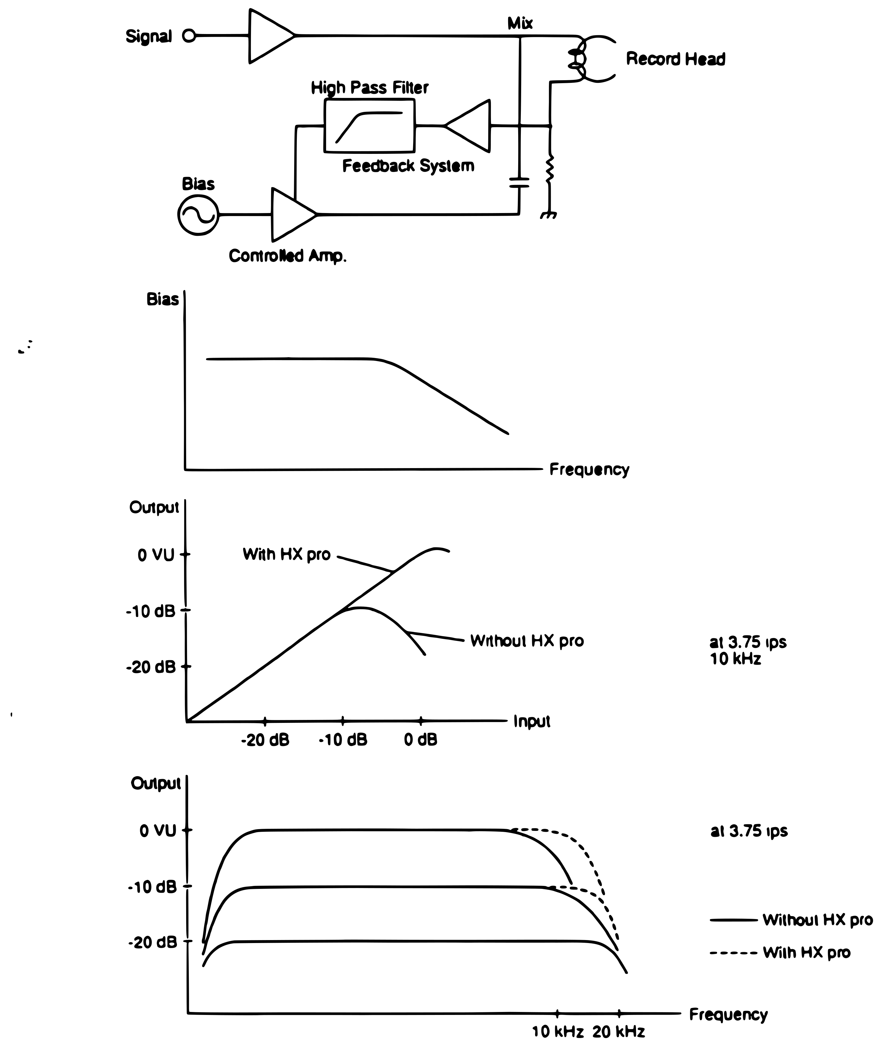 ⤢ zoomDolby HX pro feedback system block diagram, bias versus frequency, and output curves with and without HX pro at 3.75 ips
7. BALANCED LINE AND ACTIVE BALANCED LINE↑ TOP
A. BALANCED INPUT/OUTPUT↑ TOP
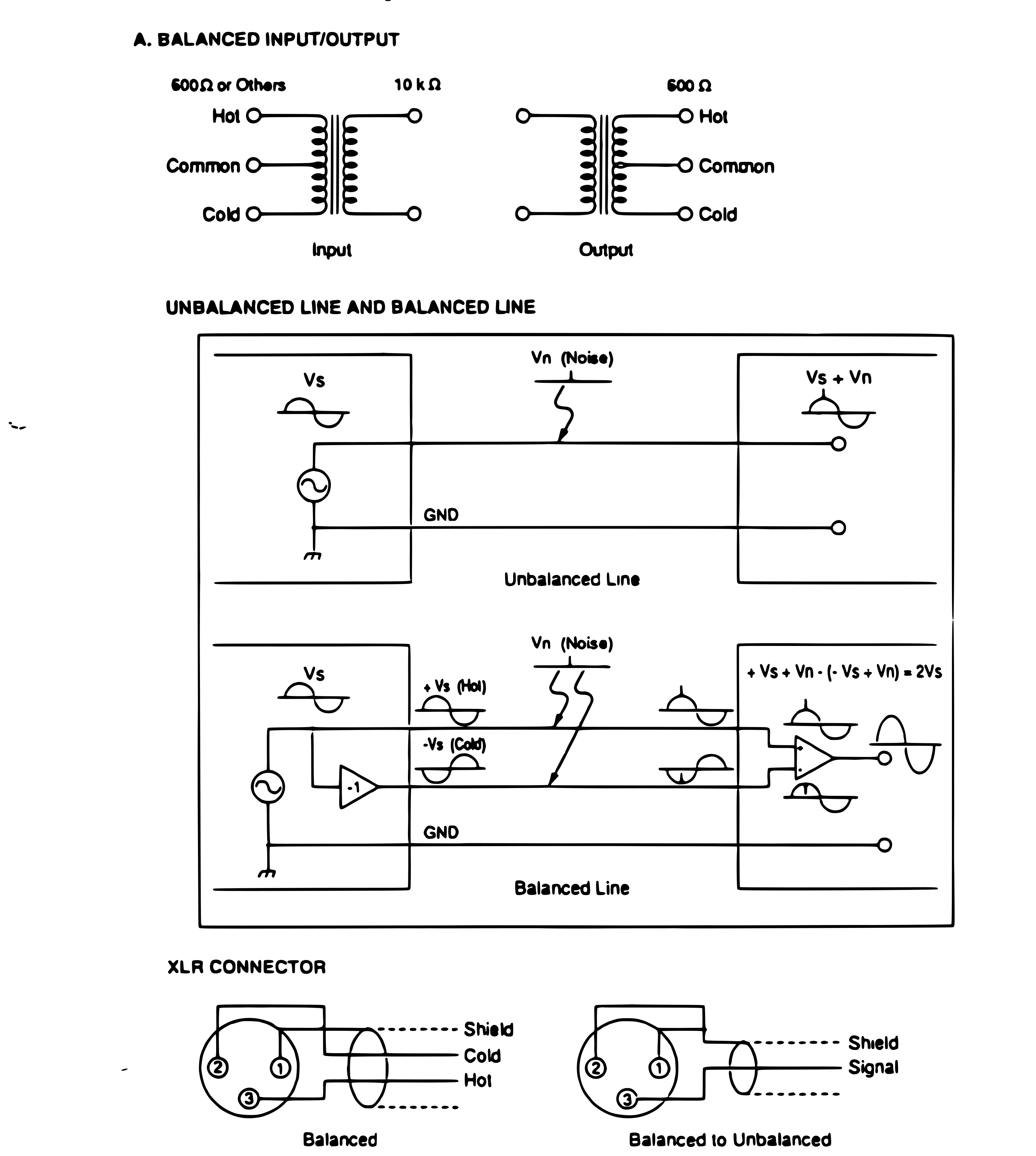 ⤢ zoomTransformer balanced input and output, unbalanced line versus balanced line noise rejection, and XLR connector wiring
Some standards assign Pin 2 as Hot, Pin 3 as Cold. (CAUTION: If the connection is mixed in one system, some problems might occur.)
B. ACTIVE BALANCED INPUT/OUTPUT↑ TOP
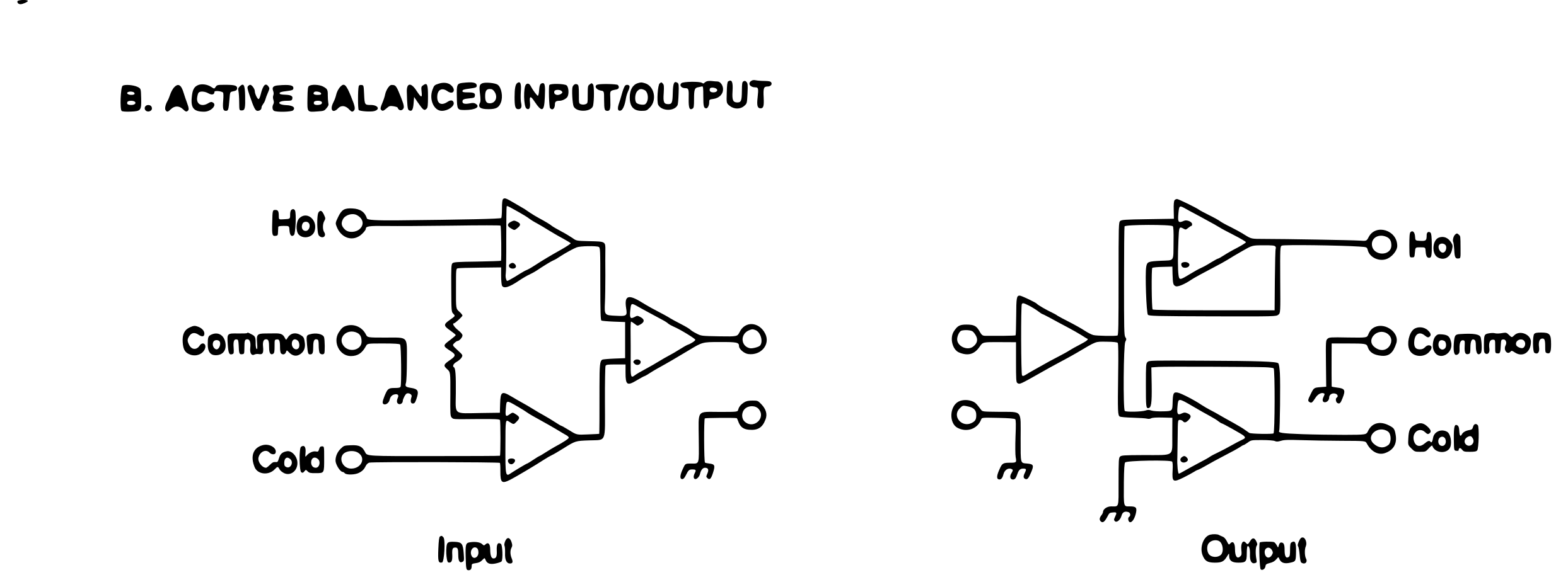 ⤢ zoomActive balanced input and output op-amp circuits
Advantages
- Wide Band Frequency Responce
- Compact Size
- Low Cost
- High Impedance Input (10 kΩ - 1 MΩ) / Low Inpedance Output (1Ω - 5Ω)
PLAYBACK AND RECORD EQUALIZATION↑ TOP
Theory of Equalization
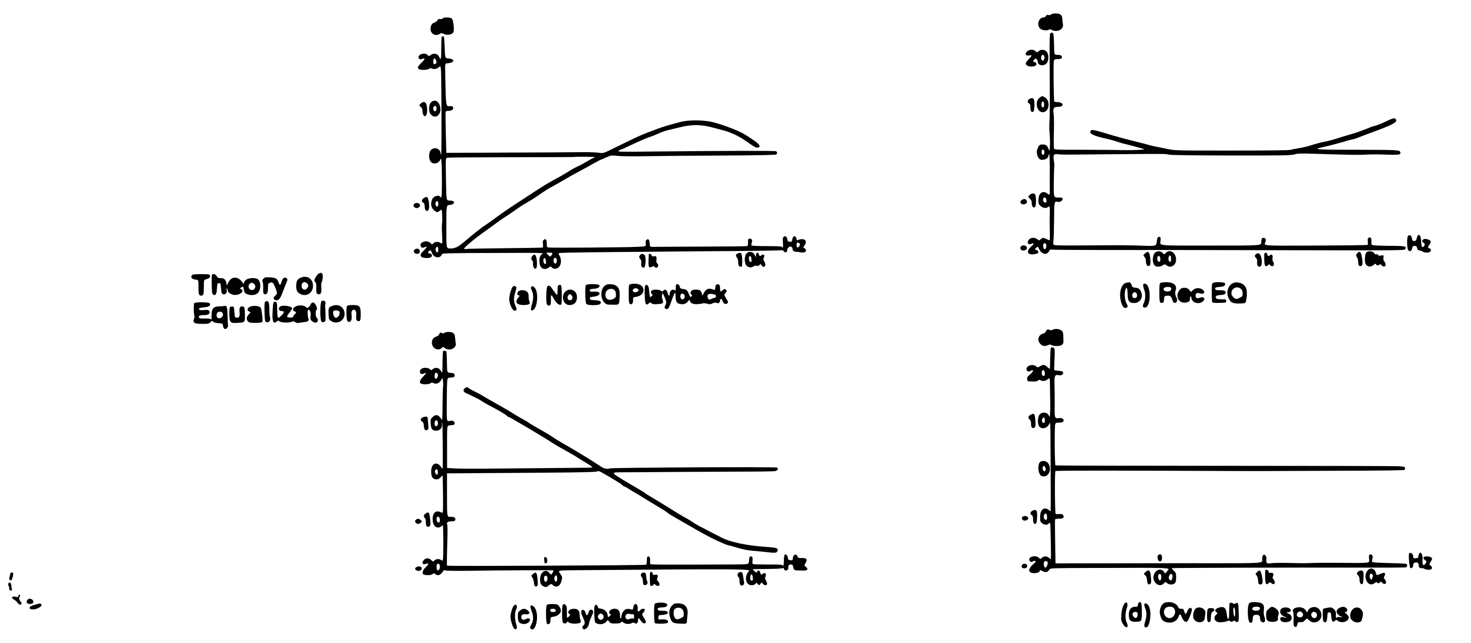 ⤢ zoomTheory of equalization — (a) no EQ playback, (b) rec EQ, (c) playback EQ, (d) overall response
Constants of Playback Equalization
TAPE SPEED (cm/sec)
| EQ Standard | 76 | 38 | 19 | 9.5 | 4.8 |
|---|---|---|---|---|---|
| AES | 17.5 | - | - | - | - |
| CCIR | - | 35 | 35 | - | - |
| DIN | - | 35 | 70(DIN19S) 50+3180 | 90+3180 | 120+3180 |
| IEC 1 | 35 | 35 | 70 | 90+3180 | 120+3180 |
| IEC 2 | 17.5 | 50+3180 | 50+3180 | - | - |
| NAB | - | 50+3180 | 50+3180 | 90+3180 | 90+3180 |
| BTS.NABJ | - | 35+3180 | 50+3180 | - | - |
| JIS | - | - | 50+3180 | 90+3180 | 120+3180 |
Playback Equalization Curves
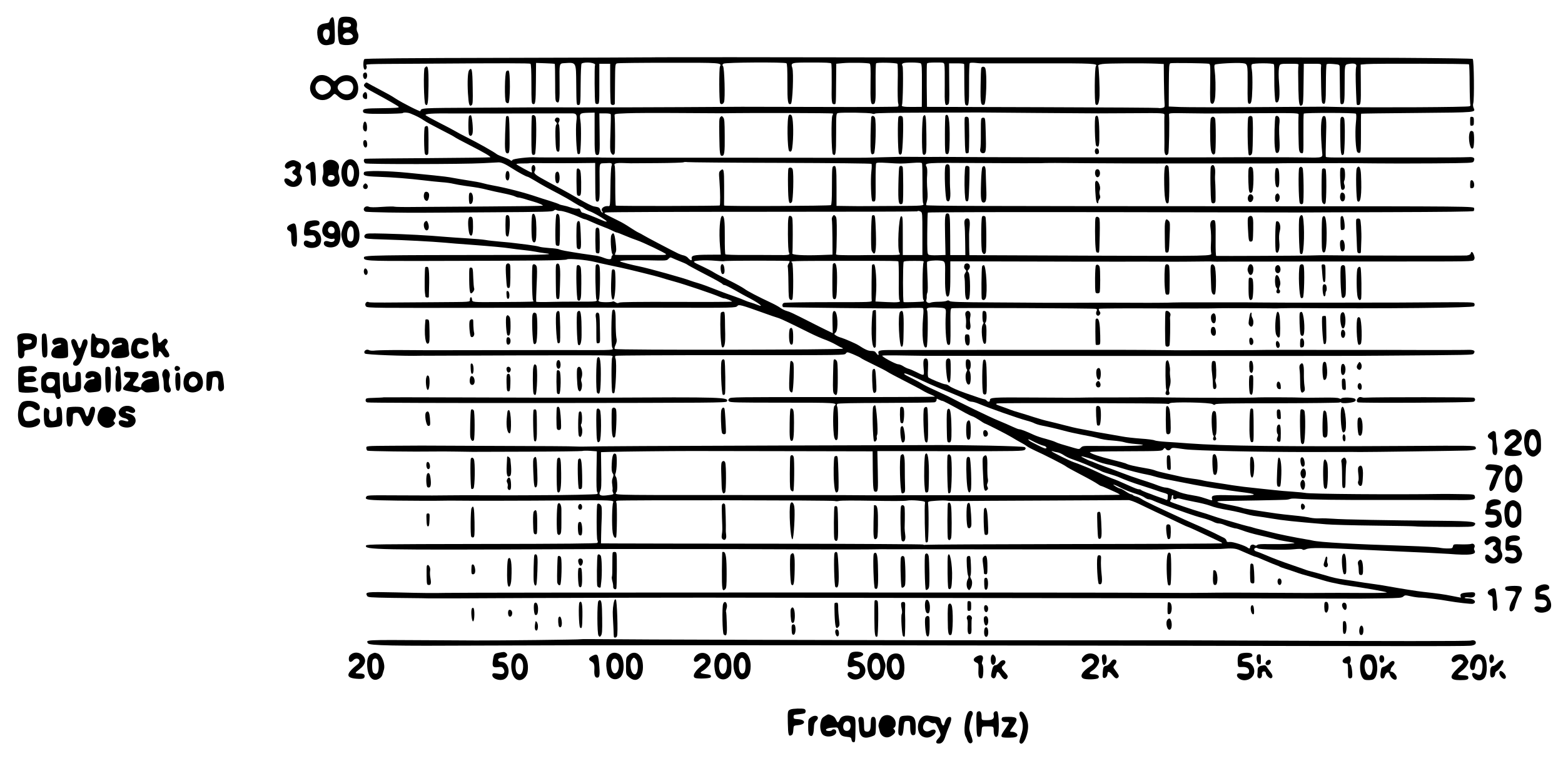 ⤢ zoomPlayback equalization curves
METER RESPONSE CURVES↑ TOP
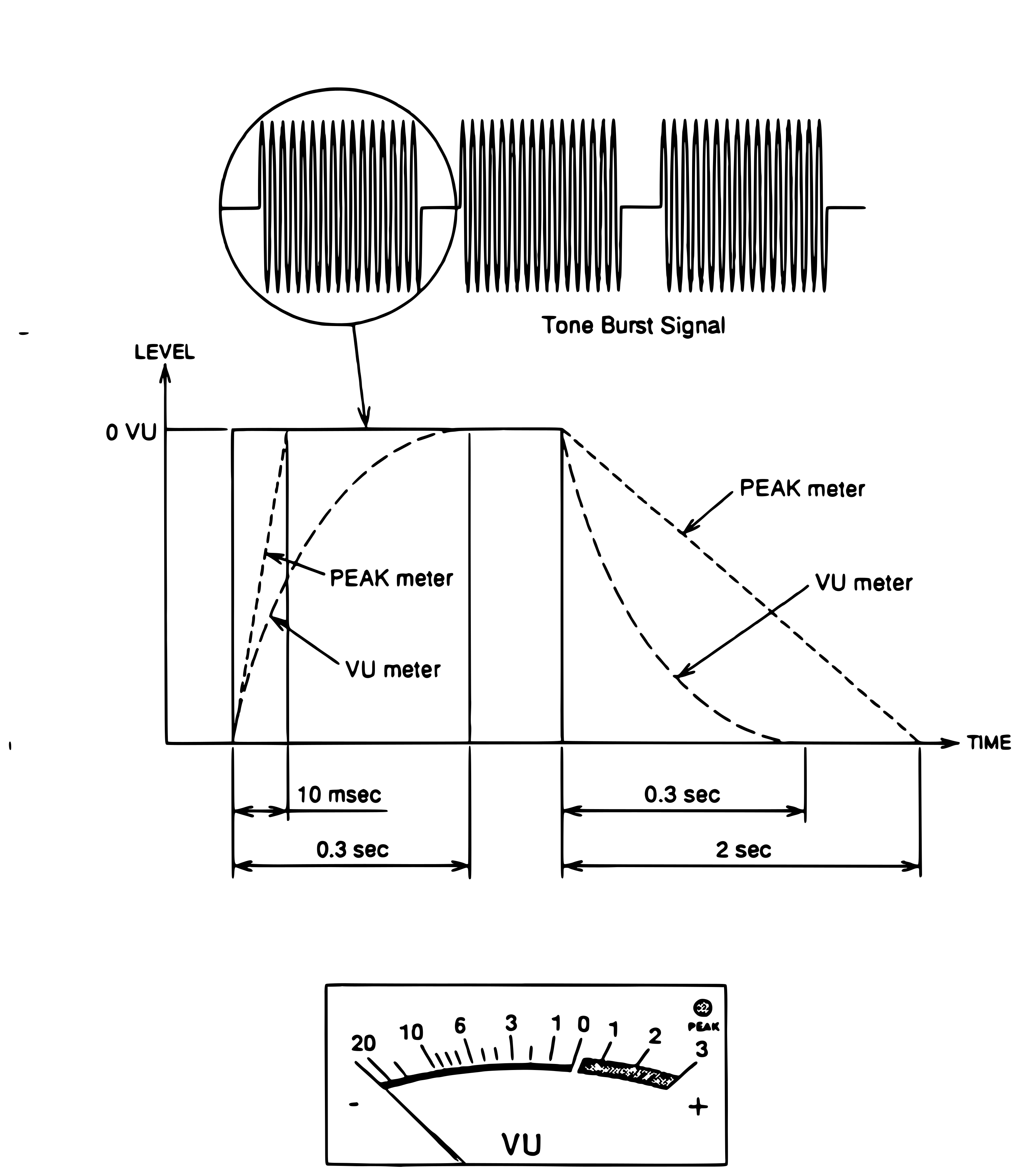 ⤢ zoomTone burst signal with PEAK meter and VU meter rise and fall ballistics, and a VU meter scale with peak indicator
TAPE CHARACTERISTICS↑ TOP
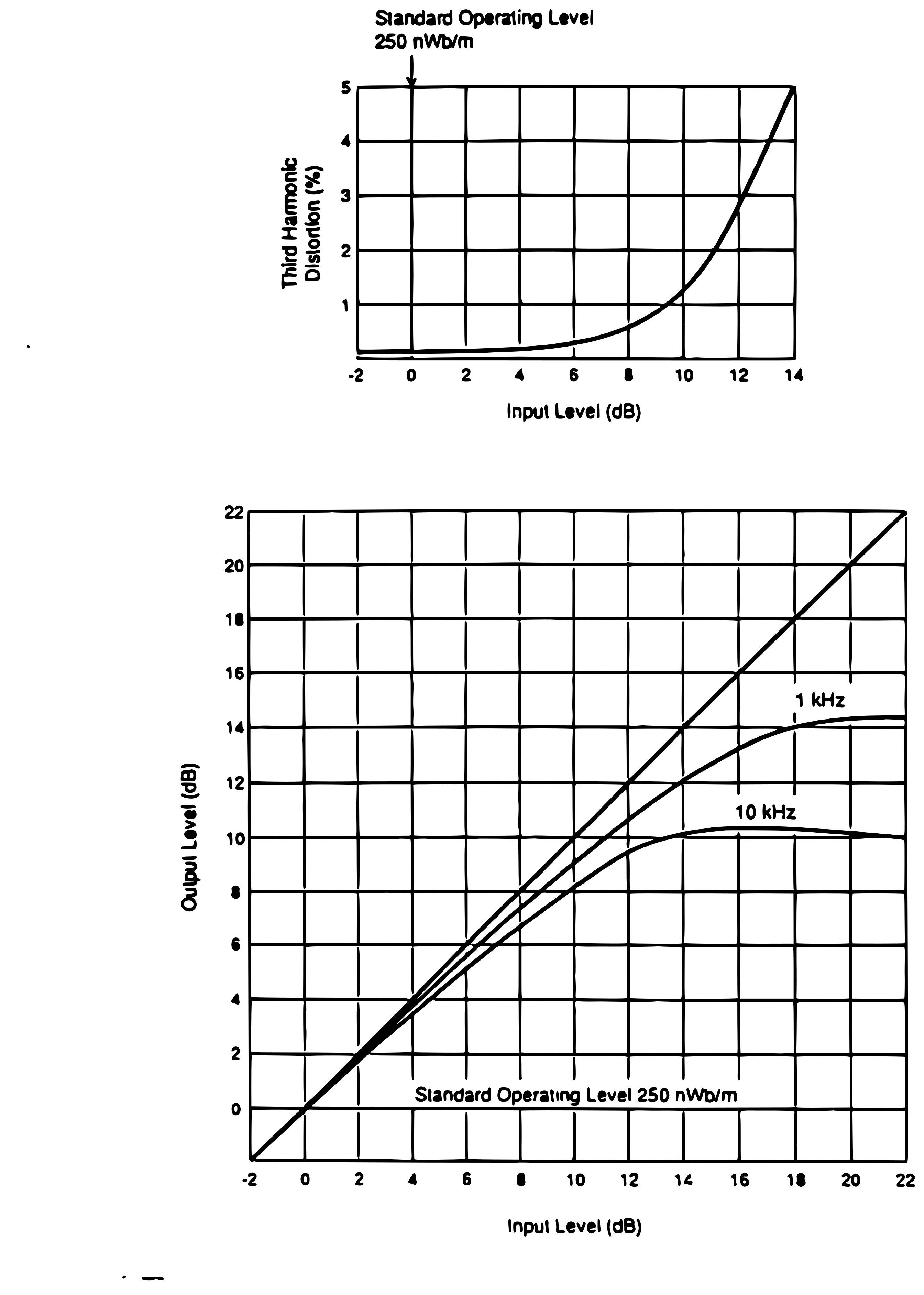 ⤢ zoomThird harmonic distortion versus input level at the 250 nWb/m standard operating level, and output versus input at 1 kHz and 10 kHz