MX-5050B Maintenance Manual — Digital Edition · Part 5 · scan pages 55-64
Major Component Replacement
5-1 REEL MOTOR ASSEMBLY REPLACEMENT↑ TOP
5-1-(1) REEL TABLE REPLACEMENT AND HEIGHT ADJUSTMENT↑ TOP
The reel table may be removed by removing the three cross-head screws accessible from the front of the transport. To adjust the reel table height, loosen the two hexagonal socket-head screws shown in Fig. 5-2, adjust the height and retighten the screws.
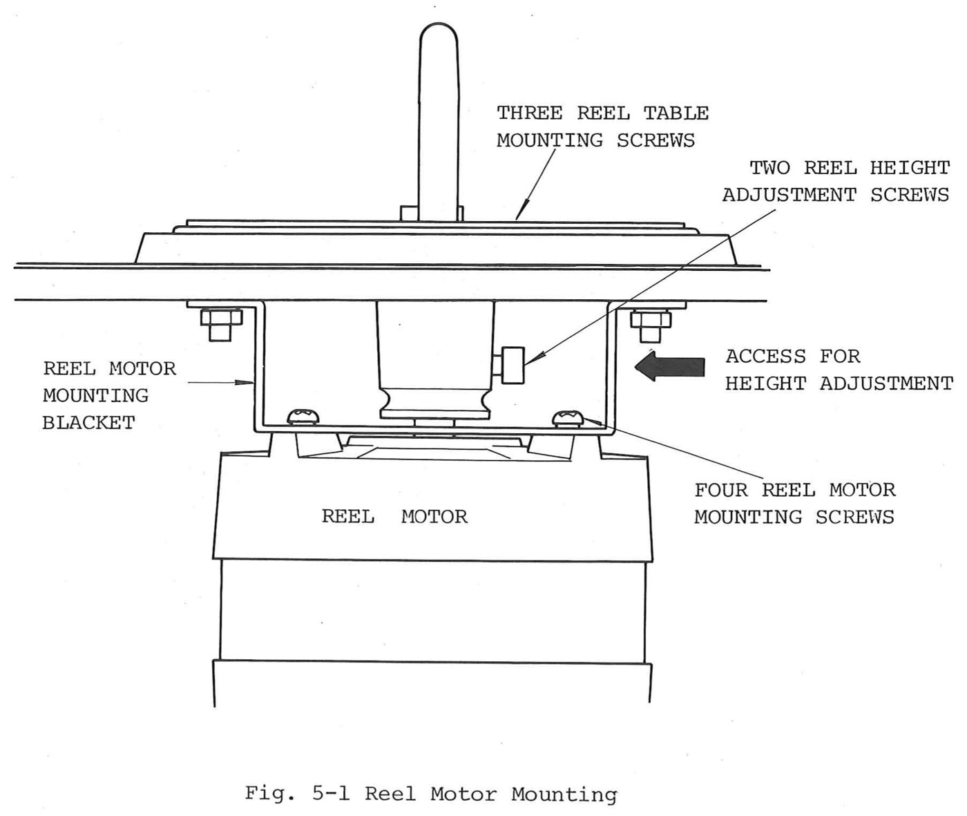 ⤢ zoomFig. 5-1 Reel Motor Mounting: the reel table on its motor shaft above the transport plate, with the three reel table mounting screws, the two reel height adjustment screws reached from the side, the reel motor mounting bracket and its four screws, and the reel motor below
5-1-(2) REEL MOTOR REPLACEMENT↑ TOP
To replace the supply or takeup motor proceed as follows:
- Loosen the two hexagonal socket-head screws on the reel shaft holder (Fig.4-1) and remove the reel table and holder.
- Tag and unsolder the motor leads attached to the printed circuit board.
- Remove the four motor mounting cross-head screws, accessible from the front of the transport.
- Remove the brake assembly by removing the four brake assembly mounting screws on the bottom of the reel motor as shown in Fig. 5-2.
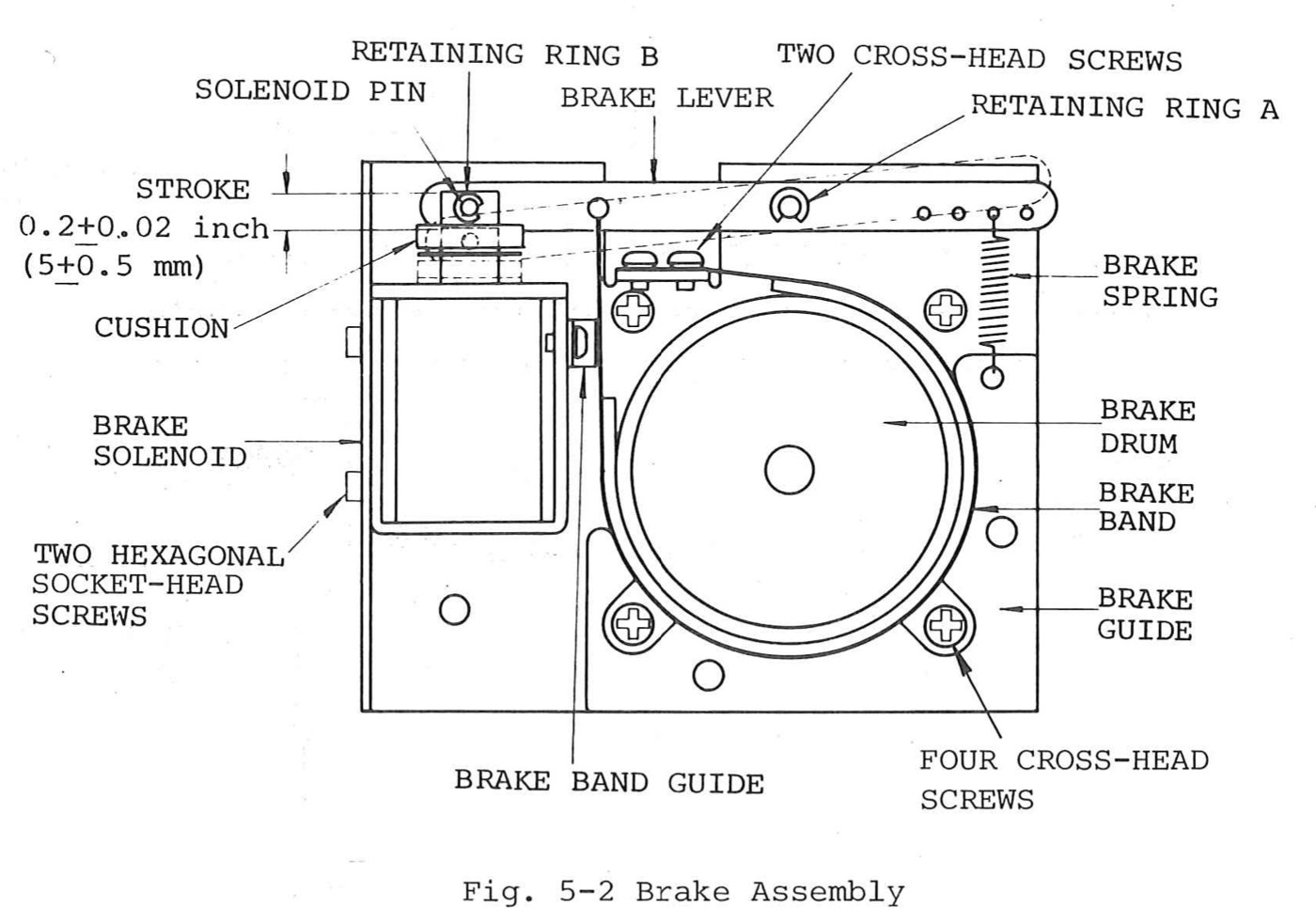 ⤢ zoomFig. 5-2 Brake Assembly: brake drum, band, brake guide and band guide, with the brake lever, its two cross-head screws, the brake spring, the solenoid pin and retaining rings A and B along the top, the brake solenoid and its cushion at the left with the solenoid stroke marked 0.2±0.02 inch (5±0.5 mm), the two hexagonal socket-head screws, and the four cross-head screws
5-1-(3) BRAKE BAND AND BRAKE SOLENOID REPLACEMENT↑ TOP
When a new brake band or new brake solenoid is installed (Fig. 5-2), it is necessary to position the brake guide and/or brake solenoid to ensure that is uniform brake band clearance around the brake drum when the solenoid is energized.
Also, the brake solenoid plunger must bottom in the solenoid housing when the solenoid is energized.
When the solenoid is de-energized, the brake band should uniformly contact the drum surface.
After installation, perform the brake adjustment procedure in Section 3 of this manual.
After completion of the adjustments, place the recorder in the play mode for 30 minutes.
Then press the STOP and PLAY pushbuttons to ensure that the solenoid bottoms when it is hot.
To replace the brake band, proceed as follows:
The brake band is replaced together with the brake lever as assembly.
- Remove the retaining ring "A" and "B", and remove the brake spring.
- Remove the two cross-head screws, and replace the brake band and brake lever.
To replace the brake solenoid, proceed as follows.
- Remove the brake spring.
- Remove retaining ring B on the solenoid pin and remove the solenoid pin.
- Remove the solenoid housing and plunger by removing the two hexagonal socket screws.
- Install a new solenoid housing and plunger and adjust the solenoid for 0.2±0.02 inch plunger stroke by loosing two hexagonal socket-head screws.
5-2 POWER TRANSFORMER REPLACEMENT↑ TOP
To replace the power transformer (refer to EXPLODED VIEW 13), proceed as follows:
- Tag and unsolder all transformer leads.
- Remove the four M4 nuts that secure the transformer to the transport.
- Install a new transformer in the reverse order of removal, and resolder the leads to the terminals on the transformer.
5-3 CAPSTAN AND CAPSTAN MOTOR REPLACEMENT↑ TOP
This section provides separately both dc servo capstan motor and hysteresis synchronous capstan motor replacement procedures.
5-3-(1) DC SERVO CAPSTAN MOTOR↑ TOP
The capstan motor should be replaced along with the servo control printed circuit board assembly. To replace the capstan motor proceed as follows:
- Remove the capstan pinch roller by removing the screw on the pinch roller cap and remove the capstan dust cap by turning the dust cap counterclockwise.
- Remove the connector on the servo control printed circuit board assembly located above the capstan.
- Remove the servo control printed circuit board assembly and its mounting plate by turning the four M3 cross-head screws (B) on the mounting plate.
- Remove the capstan mounting plate and capstan motor by removing the four M4 cross-head screws (A) on the mounting plate.
- Remove the capstan motor by removing the three M4 cross-head screws (C) on the mounting plate and install a new capstan assembly in the reverse order of removal.
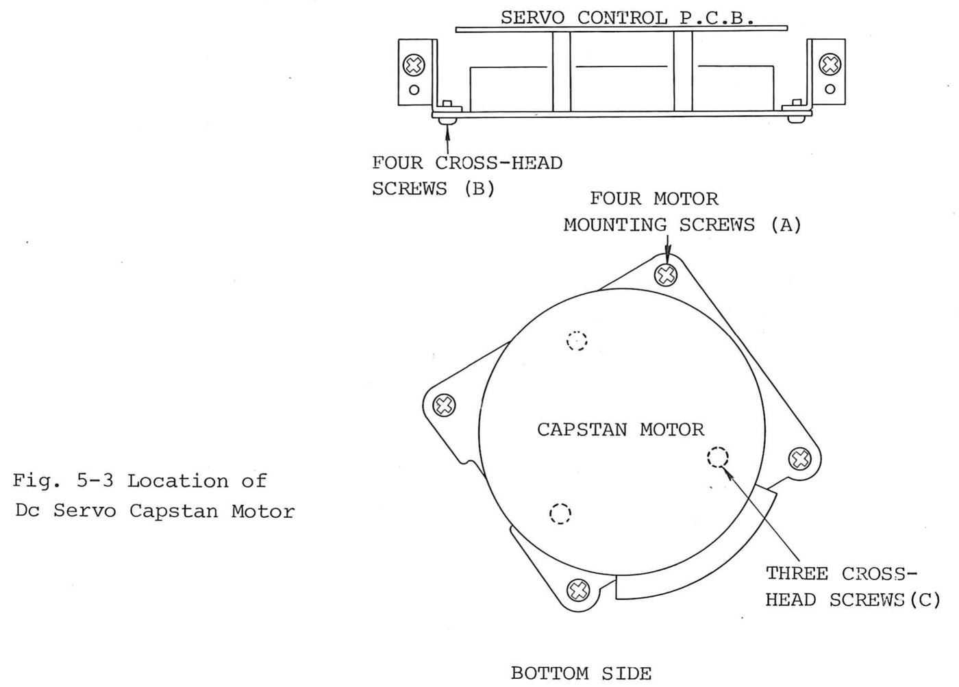 ⤢ zoomFig. 5-3 Location of Dc Servo Capstan Motor: the servo control p.c.b. seen edge on with its four cross-head screws (B), and below it the capstan motor from the bottom side with its four motor mounting screws (A) and three cross-head screws (C)
5-3-(2) HYSTERESIS SYNCHRONOUS CAPSTAN MOTOR↑ TOP
On the hysteresis synchronous capstan motor version, the capstan assembly and capstan motor are seperately replaced. To replace the capstan assembly and capstan motor, proceed as follows:
For the capstan motor:
- Remove the capstan belt from the motor pulley and the capstan fly-wheel.
- Remove the capstan motor assembly with the mounting plate by removing four cross-head screws "A".
- Remove the motor by loosning two screws (B).
- Install a new motor in the reverse order.
For the capstan assembly:
- Remove the capstan pinch roller by removing the screws on the pinch roller cap and remove the capstan dust cap by turning it counterclockwise.
- Remove the capstan shaft with fly-wheel.
- Remove the capstan holder by removing three holder mounting screws.
- Install a new capstan holder and capstan shaft with fly-wheel in the reverse order.
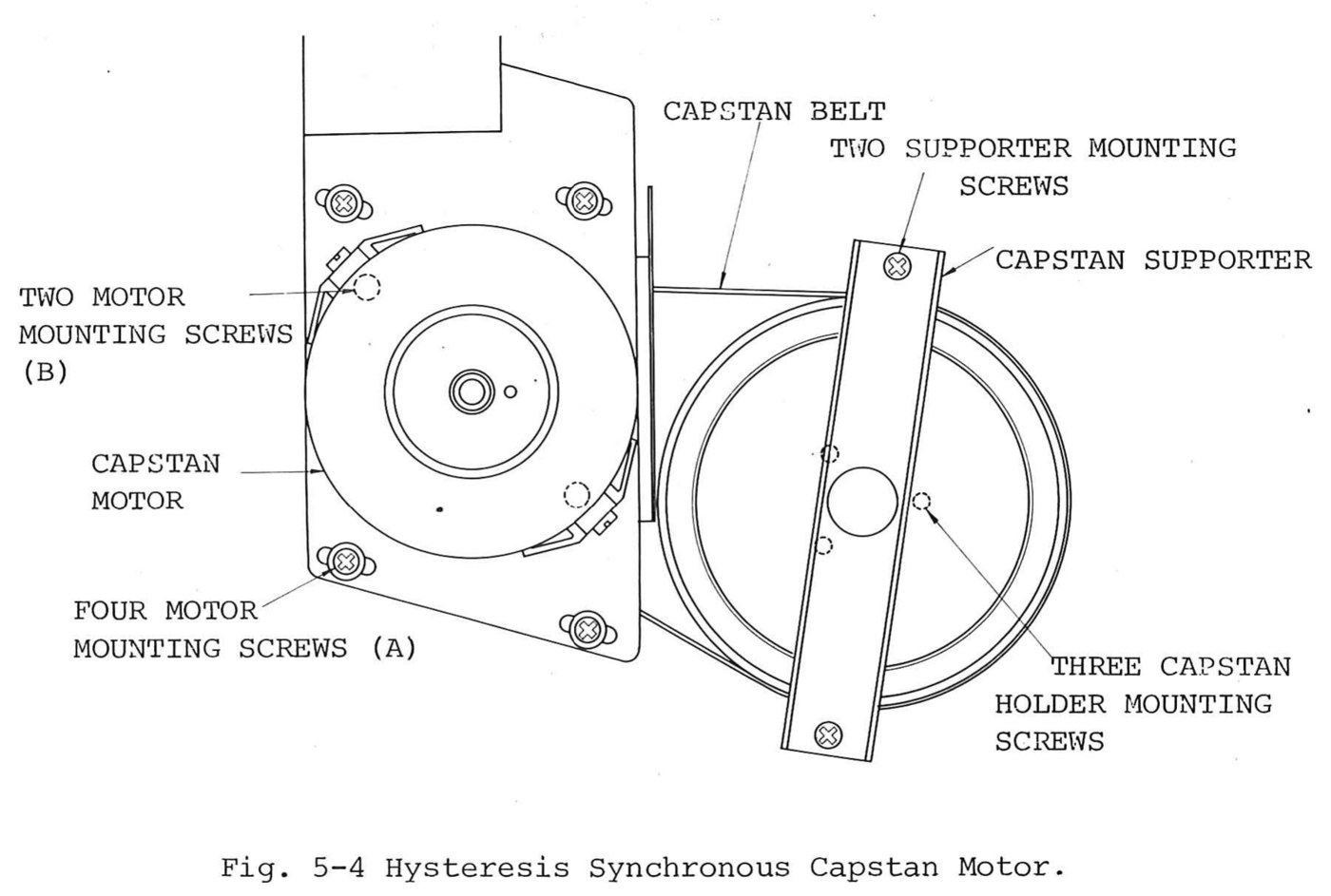 ⤢ zoomFig. 5-4 Hysteresis Synchronous Capstan Motor: the capstan motor on its mounting plate beside the capstan fly-wheel, the capstan belt between them, with the two motor mounting screws (B), four motor mounting screws (A), the capstan supporter and its two mounting screws, and the three capstan holder mounting screws
5-4 PINCH ROLLER REPLACEMENT↑ TOP
To replace the pinch roller assembly proceed as follows:
-
Remove the pinch roller cap by removing the screw on it.
NOTE: There are polyslider washers on both sides of the pinch roller.
-
Install a new pinch roller, the polyslider washers, and pinch roller cap in the reverse order.
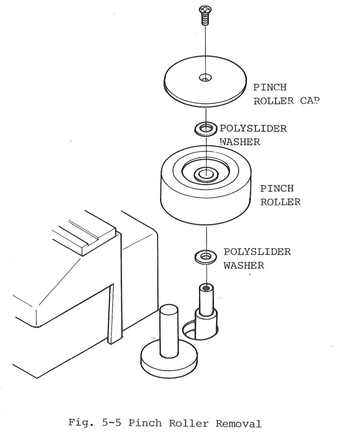 ⤢ zoomFig. 5-5 Pinch Roller Removal: an exploded view of the pinch roller on its shaft: the screw, pinch roller cap, a polyslider washer, the pinch roller and a second polyslider washer
5-5 HEAD ASSEMBLY REPLACEMENT↑ TOP
This section provides a description of the head assembly, the procedure for changing the head stack, and the adjustment procedure for adjusting head azimuth (tilt), head height, head zenith (perpendicularity),and tape wrap (racking).
These adjustment are required whenever a head stack is replaced.
5-5-(1) DESCRIPTION↑ TOP
The head assembly is mounted on three tape-guide posts and secured in place by the three screws labeled "M" in Fig. 5-6.
The insulating shield for the head assembly printed circuit board is secured by the screws labeled "S".
Each head stack is secured to a bracket by the screws labeled "W" with a spacer between the bracket and the head stack.
Each bracket is suspended from the head base by the three spring-loaded screw labeled "H", "A", and "T".
Screws labeled "W" are used to adjust tape wrap.
Screws labeled "H", "A", and "T" are used to adjust height, azimuth, and zenith.
A head stack may be removed and re-lapped (face resurfaced) if the amount of wear is small and only an indication of poor head-to-tape contact is evident.
Poor contact is the result of improper adjustment and is evidenced by loss of high frequency response of the record or reproduce head stack, difficulty in achieving bias peak (record stack), and insufficient erase stack erasure.
5-5-(2) HEAD STACK REPLACEMENT↑ TOP
To change a head stack, proceed as follows:
- Lift the head cover and remove the ac power cord.
- Remove the three screws labeled "M" and pull the head assembly out from the head connector.
- Tag and unsolder (use a low wattage pencil type iron to prevent damage) the leads at the rear terminal of the head stack.
- Remove the head stack by removing the two screws labeled "A", "T", and "H".
- Install a new head stack and resolder the leads.
- As a preliminary adjustment, measure the distance between the head base and the bracket at a point near spring-loaded screws "A", "T", and "H". If necessary adjust the screws for equal spacing.
- Paint the head face with a soft crayon, run the tape for about ten seconds, and check the crayon rubbed away by the tape. If tape wrap is incorrect, adjust the wrap by loosening the screws labeled "W" as shown in Fig. 5-6.
Head alignment and the following adjustments are necessary whenever the head is replaced.
-
In the case of reproduce head replacement.
A. Reproduce equalization adjustment.
B. SRL adjustment.
-
In the case of record head replacement.
A. Record bias adjustment.
B. Overall frequency response adjustment.
C. Record level adjustment.
-
In the case of erase head replacement
A. Record bias adjustment.
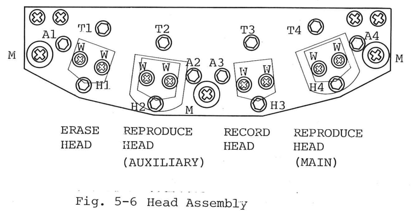 ⤢ zoomFig. 5-6 Head Assembly: the head assembly seen from above: erase, auxiliary reproduce, record and main reproduce heads, each with its azimuth (A), height (H), zenith (T) and wrap (W) screws, and the three mounting screws (M)
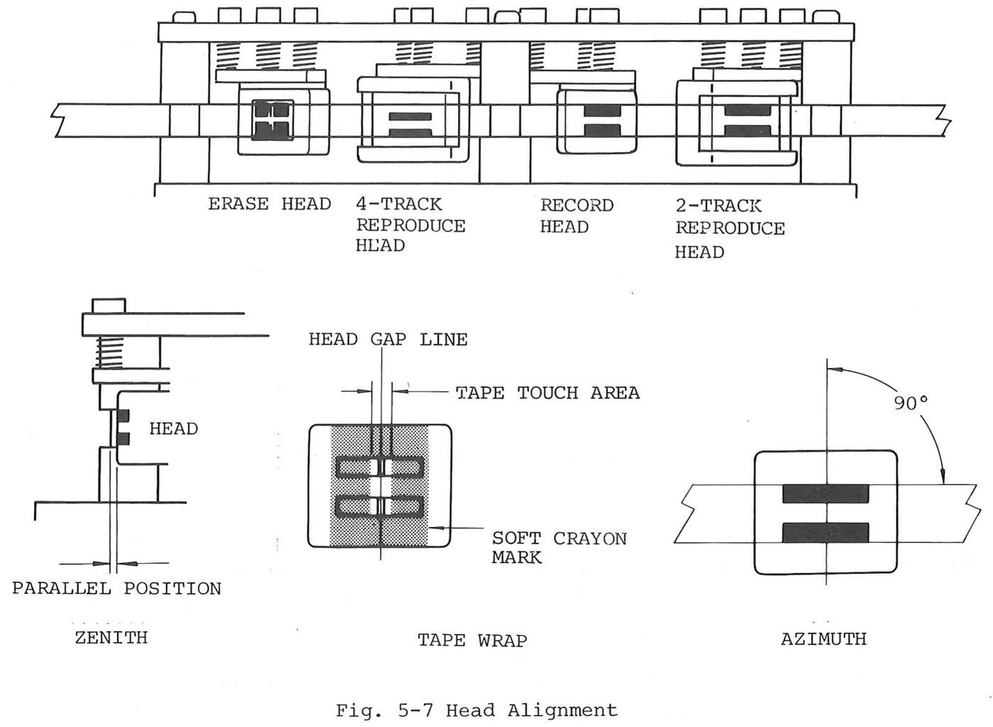 ⤢ zoomFig. 5-7 Head Alignment: the four head stacks along the tape path, then three details: zenith, the head parallel to the tape guide; tape wrap, the tape touch area centred on the head gap line within the soft crayon mark; and azimuth, the gap at 90° to the tape
5-6-(3) RECORD AND REPRODUCE HEAD ADJUSTMENT↑ TOP
Follow the procedure for reproduce system adjustment given in section 4 of this manual.
For the final adjustment of a record stack, the height and azimuth adjustment may be accomplished in the same manner as for a reproduce head stack, by playing back an alignment tape with the equpment in the selective reproduction mode (SEL/REP switches "in").
5-6-(4) ERASE HEAD ALIGNMENT↑ TOP
Erase head azimuth is not critical, however wrap angle and head height relative to the record head are important to achieve maximum efficiency.
Poor erasure is often caused by misalignment of the erase head.
Before making any attempt to adjust the erase head stack, an entire electronic alignment procedure (reproduce, record, and bias alignment) should be performed so that the record and reproduce head height are correct, the SRL adjustment is correct, and bias and record levels are properly calibrated.
An approximate erase head adjustment can be accomplished by using a headset or a speaker/amplifier.
However, for precise alignment, a wave analyzer should be used.
Proceed as follows
- Follow the procedure for the erasure test steps 1 through 6 given in Section 4-5-(4).
- Observe the reading on the wave analyzer and turn screw "H" (Fig. 5-6) 1/4 turn clockwise. If the reading decreases, turn the screws "A" and "Z" 1/4 turn clockwise. If the reading increases when "H" is turned 1/4 turn clockwise, turn "H" counterclockwise past the original setting to 1/4 turn counterclockwise. If the reading decreases, turn screws "A" and "T" counterclockwise by the same amount.
- Repeat step 2 in small increments to achieve a minimum reading on the wave analyzer. Typical amount of erasure should be 65 dB or better. Note: After the screw "H" is turned, be sure to turn the screws "A" and "T" the same amount.
- If adjustment of the erase head height alone does not achieve satisfactory erasure, set screws "H","A", and "T" for a minimum reading on the wave analizer. Note that there are two gaps on the face of the erase head. The trailing gap has the most effect on erasure and must have good contact with the tape. Loosen screws "W" slightly and rotate the erase head stack for a minimum reading on the wave analyzer. Tighten screws "W".