MX-5050B Maintenance Manual — Digital Edition · Part 6 · scan pages 65-100
Parts Lists and Schematics
When ordering parts, the part number must be specified. Components which do not have part numbers should be specified by a reference number.
Concerning components on the printed circuit boards, those which have part numbers should be specified by their respective part number, and those which do not have part numbers should be specified either by their assembly name or reference numbers.
NOTE
-
The part numbers in parenthesis are included in the assembly numbers indicated in the "Notes" next to those "Parts No.", therefore, those parts must be specified by the assembly numbers.
-
There are several versions of the MX-5050B depending on the capstan motor type, the tape speeds pair, and the track format, therefore, those parts may differ depending on each version.
Since the exploded views in this manual show the MX-5050B-2HD and 2LD as standard, confirm a required part number for other versions by the appropriate parts list.
PARTS LIST 1 CASE PARTS↑ TOP
| Ref. No. | Description | Part No. | Notes |
|---|---|---|---|
| 1-1 | Foot, Rear | CY4013 | |
| 1-2 | Cover Ass'y, Rear | K102903 | Ass'y K102903 |
| 1-3 | Felt, A. Rear Cover | (PZ1B029) | Ass'y K102903 |
| 1-4 | Felt, B. Rear Cover | (PZ1B030) | Ass'y K102903 |
| 1-5 | Rubber, sheet Rear Cover | (PZ1C038) | Ass'y K102903 |
| 1-6 | Rubber, Block Rear Cover | (PZ1C023) | Ass'y K102903 |
| 1-7 | Escutcheon, Ventilate | CY5001 | |
| 1-8 | Bracket, B. Ventilate | K102908 | |
| 1-9 | Board, Side | K102902 | |
| 1-10 | Washer, Trim, Side Board | KZ6C016 | |
| 1-11 | Grip, Side Board | CY1004 | |
| 1-12 | Bracket, A. Ventilate | K102907 | |
| 1-13 | Angle, L, Bottom Cover | K102909 | |
| 1-14 | Angle, R, Bottom Cover | K102910 | |
| 1-15 | Cover, Bottom | K102906 | |
| 1-16 | Foot, Bottom | CY4011-A |
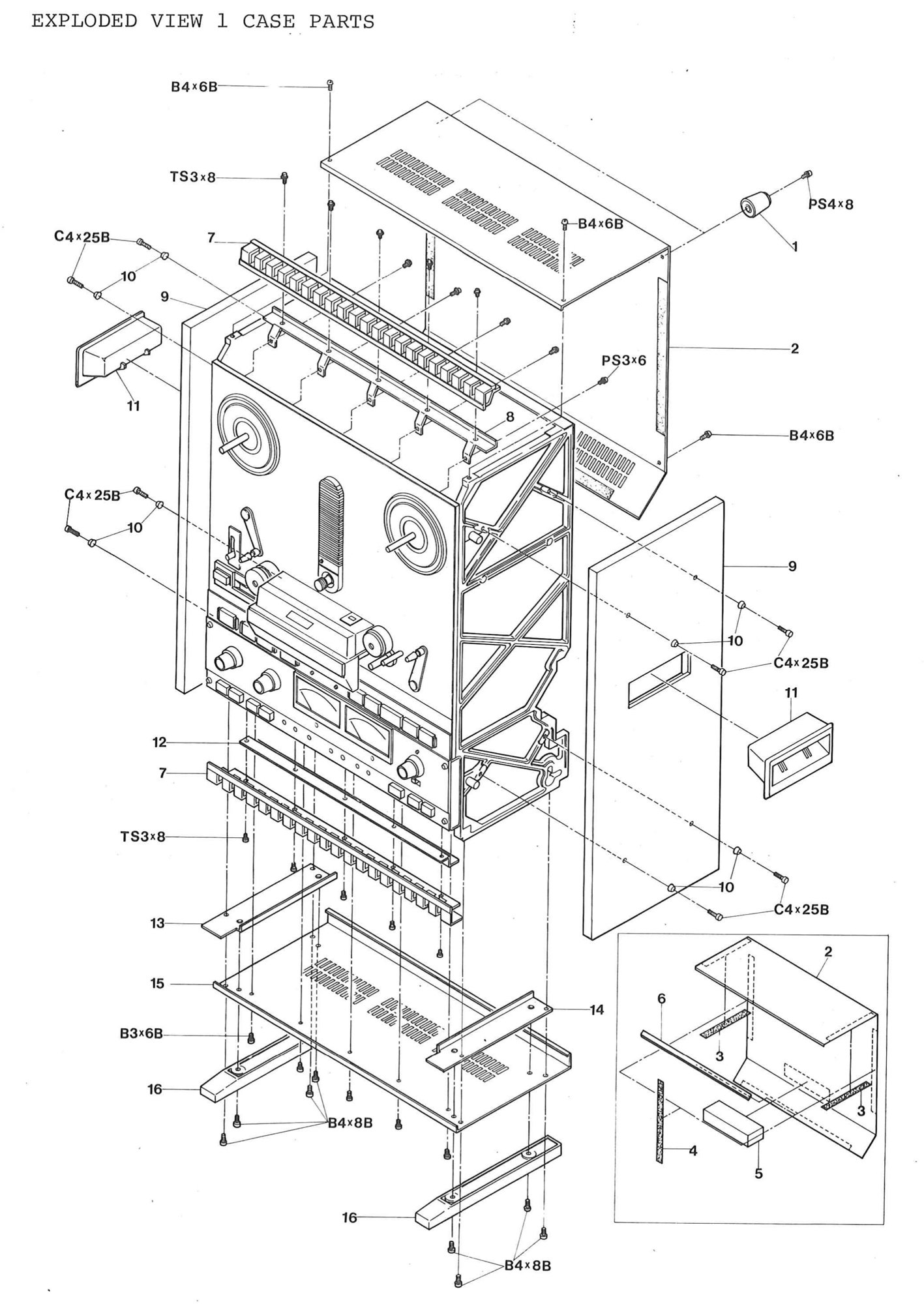 ⤢ zoomEXPLODED VIEW 1 CASE PARTS: the cabinet around the transport: the rear cover assembly with its felts and rubbers, drawn again in an inset, the ventilation escutcheons and brackets, the side boards with their trim washers and grips, and the bottom cover with its angles and feet
PARTS LIST 2 PINCH ROLLER and LIFTER ASSEMBLY↑ TOP
| Ref. No. | Description | Part No. | Notes |
|---|---|---|---|
| 2-1 | Angle, Spring Hook | KZ3A023 | |
| 2-2 | Spring, Roller Arm | GS1011 | |
| 2-3 | Arm, Pinch Roller | KP4B002 | |
| 2-4 | Retaining Ring, E Type ø4 | F754 | |
| 2-5 | Nuts, M4, Rod | F517-4 | |
| 2-6 | Spring, Pressure, Rod | GS2003 | |
| 2-7 | Washer, Spherical, Rod | KP0G004 | |
| 2-8 | Washer, Fiber ø5 | F526-5 | |
| 2-9 | Retaining Ring, E Type ø3 | F753 | |
| 2-10 | Cushion,Solenoid | PZ1C021 | |
| 2-11 | Rod, Solenoid | KZ6A022 | |
| 2-12 | Retaining Ring E Type ø2 | F752 | |
| 2-13 | Limit Stop. Solenoid | KZ2A016 | |
| 2-14 | Solenoid, Pinch Roller | GP1B06 | |
| 2-15 | Pin Solenoid | KZ5A003 | |
| 2-16 | Shaft, Pinch Roller | KP0B010 | |
| 2-17 | Washer, Polyslider. ø6x0.25 | F523-6 | |
| 2-18 | Pinch Roller, | KP0A007 | |
| 2-19 | Cap, Pinch Roller | KP0C012 | |
| 2-20 | Shaft, Roller Arm | KP4B001 | |
| 2-21 | Spring, Lifter Arm | GS1028-A | |
| 2-22 | Arm, Lifter A | KR0B005 | |
| 2-23 | Arm, Lifter B | KR0B006 | |
| 2-24 | Tube, Vinyl, Lifter Arm | KR4F001 | |
| 2-25 | Shaft, Lifter Arm | KR4B001 | |
| 2-26 | Arm, Cue | (KR4B008) | Ass'y KR-4F-A |
| 2-27 | Felt, Cushion, Cue Arm, | (PZ1B009) | Ass'y KR-4F-A |
| 2-28 | Shaft, Cue Arm | KR4B007 | |
| 2-29 | Felt, Blind, Cue Arm | PZ1B001 | |
| 2-30 | Catch, Cue Arm | CY3001 | |
| 2-31 | Plate, Guide, Cue Arm | KR4B011 | |
| 2-32 | Knob, Cue Arm | KR4F002 | |
| 2-33 | Escution, Cue | KR4B006 |
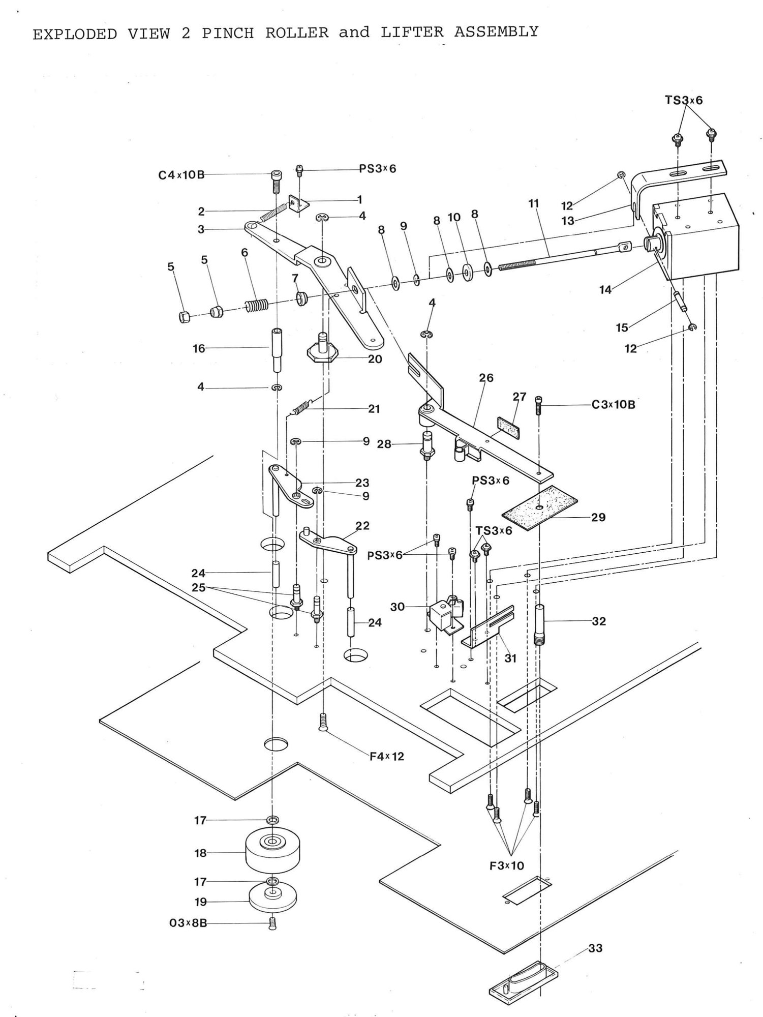 ⤢ zoomEXPLODED VIEW 2 PINCH ROLLER and LIFTER ASSEMBLY: the pinch roller arm with its pressure rod, springs and solenoid, the pinch roller on its shaft with polyslider washers and cap, the tape lifter arms, and the cue arm with its felts, knob, guide plate and escutcheon
PARTS LIST 3 CAPSTAN ASSEMBLY (DC SERVO VERSION)↑ TOP
| Ref. No. | Description | Part No. | Notes |
|---|---|---|---|
| 3-1 | Bracket, R, Capstan P.C, Board | KC4H004 | |
| 3-2 | Bracket, L, Capstan P.C, Board | KC4H003 | |
| 3-3 | Motor, Capstan | MR5A008 | |
| 3-4 | Plate, Capstan Motor | KC4H001 | |
| 3-5 | Stud, Capstan Motor | KZ7B220 | |
| 3-6 | Resistor, Var. 500Ω | RV252009 | |
| 3-7 | Bracket, Resistor, Var | KC4H002 | |
| 3-8 | Felt, Potentiometer | PZ1B037 | |
| 3-9 | Spacer, P.C, Board LED(A) | KZ7A823 | |
| 3-10 | P.C, Board Ass'y, LED,(A) | PB-81G | Ass'y PB-81G |
| 3-11 | Felt, P.C, Board LED(A) | (PZ1B038) | Ass'y PB-81G |
| 3-12 | Escutcheon, Pitch Control. | KC4H005 | |
| 3-13 | Cap, Capstan Motor | KC0B011 | |
| 3-14 | Knob, Pitch Control | KN1024 |
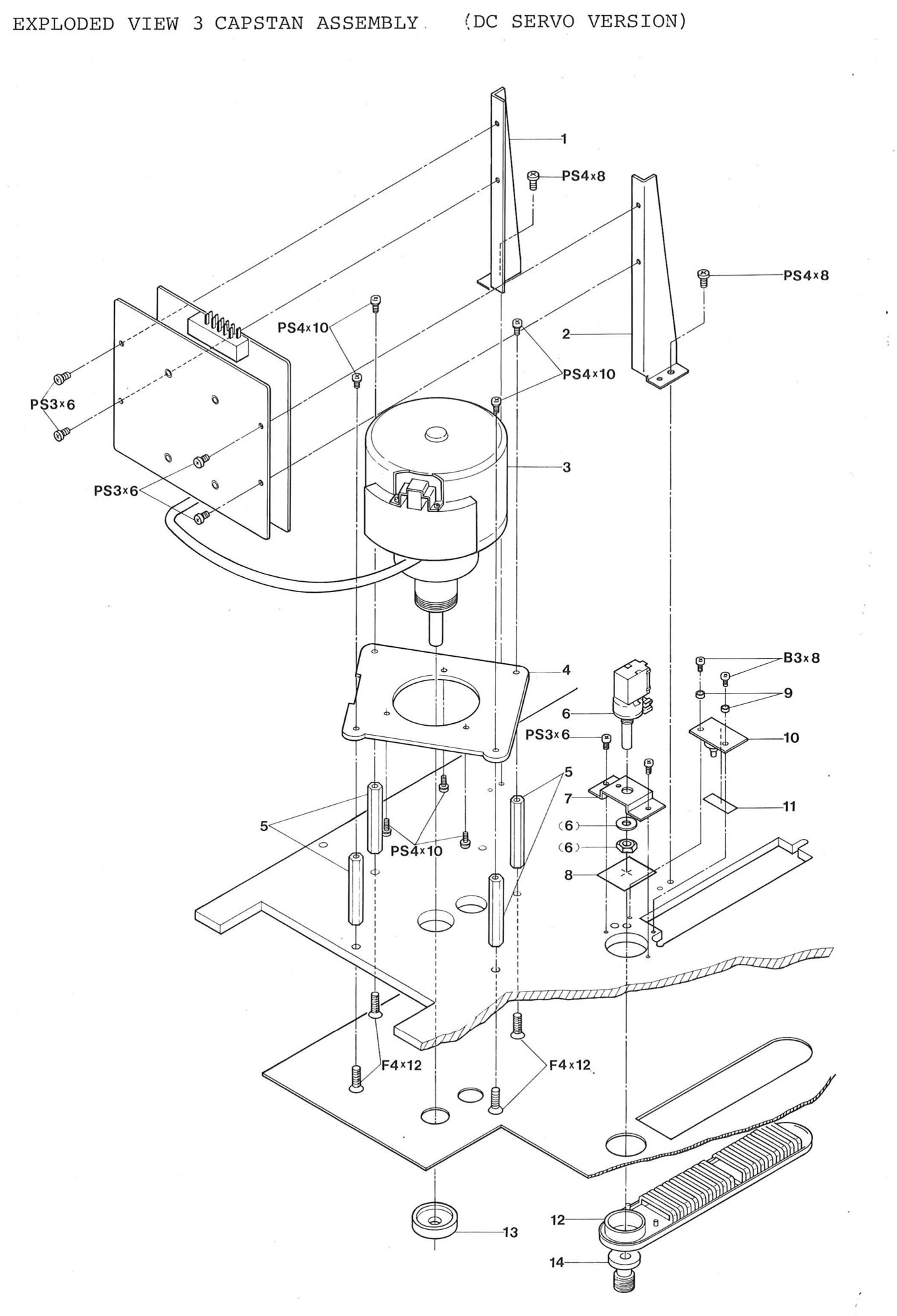 ⤢ zoomEXPLODED VIEW 3 CAPSTAN ASSEMBLY (DC SERVO VERSION): the dc servo capstan motor on its plate and studs, the capstan p.c. board brackets, the pitch control potentiometer with its bracket, escutcheon and knob, the LED board (A), and the capstan motor cap
PARTS LIST 4 CAPSTAN ASSEMBLY (HYSTERESIS VERSION)↑ TOP
| Ref. No. | Description | Part No. | Notes |
|---|---|---|---|
| 4-1 | Cap, Capstan | KC0B011 | |
| 4-2 | Felt, Capstan | PZ1B007 | |
| 4-3 | Holder, Bearing | KC4B001 | |
| 4-4 | Washer, Capstan | KZ6C014 | or. KZ6C026 adjust |
| 4-5 | Flywheel, Capstan | KC0A020 | |
| 4-6 | Belt, Flat, Capstan | BE2M128A | Low Speed |
| 4-6 | Belt, Flat, Capstan | BE2M140 | High Speed |
| 4-7 | Pulley, Capstan Motor | KC0D019 | Low Speed 60HZ |
| 4-7 | Pulley, Capstan Motor | KC0D011 | High Speed 60HZ |
| 4-7 | Pulley, Capstan Motor | KC0D018 | Low Speed 50HZ |
| 4-7 | Pulley, Capstan Motor | KC0D010 | High Speed 50HZ |
| 4-8 | Stud, Capstan Flywheel | KZ7B203 | |
| 4-9 | Plate, Capstan Flywheel | KC4B004 | |
| 4-10 | Stud, Capstan Motor | KZ7B204 | |
| 4-11 | Plate, Shield, Motor | KC4B006 | |
| 4-12 | Plate, Capstan Motor | KC4B005 | |
| 4-13 | Capacitor, Capstan Motor | CZ10011W | 2+0.5µ |
| 4-14 | P.C. Board, Capacitor | PB9A026 | |
| 4-15 | Motor, Capstan | MR2F010 |
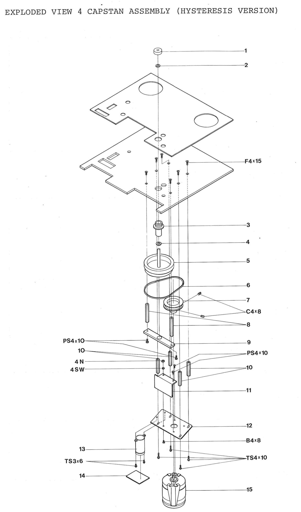 ⤢ zoomEXPLODED VIEW 4 CAPSTAN ASSEMBLY (HYSTERESIS VERSION): the capstan cap, felt and bearing holder, the flywheel and flat belt, the motor pulley, the flywheel, shield and motor plates on their studs, and the hysteresis synchronous motor with its capacitor and capacitor board
PARTS LIST 5 TENSION ARM ASSEMBLY (A) SUP.↑ TOP
| Ref. No. | Description | Part No. | Notes |
|---|---|---|---|
| 5-1 | Cap. Arm | KA0C005 | |
| 5-2 | Arm, Tension | KA0A017 | |
| 5-3 | Guide, Tension Arm | KG4D007 | |
| 5-4 | Shaft, Arm | KA4J001 | |
| 5-5 | Washer, Polyslider ø5xt0.5 | F524-5 | |
| 5-6 | Holder, Arm. | KA0B008 | |
| 5-7 | Plate, Spring Hook | KZ3A024 | |
| 5-7 | Nat, Holder | KZ6D004 | |
| 5-9 | Drum, A, Spring Retaining | KA0E004 | |
| 5-10 | Spring, Tension Arm | GS1025 | |
| 5-11 | Angle, Limit Stop | KA0H004 |
PARTS LIST 6 TENSION ARM ASSEMBLY (B) TAKE UP↑ TOP
| Ref. No. | Description | Part No. | Notes |
|---|---|---|---|
| 6-1 | Cap, Arm | KA0C005 | |
| 6-2 | Arm, Tension | KA0A017 | |
| 6-3 | Guide, Tension Arm | KG4D007 | |
| 6-4 | Shaft, Arm | KA4J001 | |
| 6-5 | Washer, Polyslider ø5xt0.5 | F524-5 | |
| 6-6 | Holder, Arm | KA0B008 | |
| 6-7 | Angle, Spring Hook | KZ3A023 | |
| 6-8 | Bracket, Magnet | (KZ3A069) | Ass'y KA-4K-A |
| 6-9 | Magnet | (GP8A01) | Ass'y KA-4K-A |
| 6-10 | Stud, | KZ7A163 | |
| 6-11 | Drum, B, Spring Retaining | KA0E005 | |
| 6-12 | Felt, Switch Actuate | (PZ1B036) | Ass'y KA-4K-B |
| 6-13 | Weight | (KA4K002) | Ass'y KA-4K-B |
| 6-14 | Arm, Switch Actuate | (KZ4K001) | Ass'y KA-4K-B |
| 6-15 | Cushion, Switch Actuate | (PZ1C007) | Ass'y KA-4K-B |
| 6-16 | Rubber, Switch Actuate | (PZ1C037) | Ass'y KA-4K-B |
| 6-17 | Spring, Tension Arm | GS1048 | |
| 6-18 | Switch, Micro | WH510011 |
PARTS LIST 7 GUIDE ROLLER ASSEMBLY↑ TOP
| Ref. No. | Description | Part No. | Notes |
|---|---|---|---|
| 7-1 | Cap, Roller | GR0A013 | |
| 7-2 | Washer, Polyslider ø6xt0.5 | F524-6 | |
| 7-3 | Shaft, Roller | GR4H001 | |
| 7-4 | Roller | GR4H002 | |
| 7-5 | Base, Roller | GR4G004 |
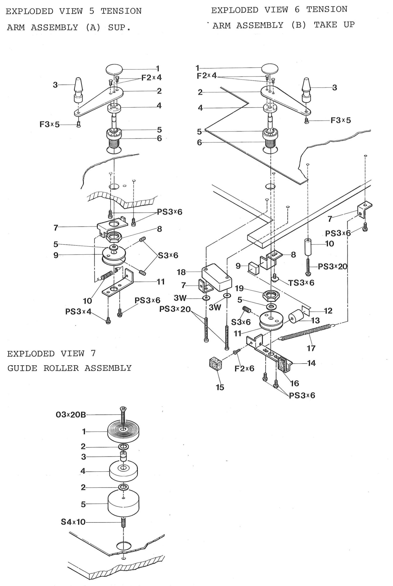 ⤢ zoomEXPLODED VIEW 5 TENSION ARM ASSEMBLY (A) SUP., EXPLODED VIEW 6 TENSION ARM ASSEMBLY (B) TAKE UP and EXPLODED VIEW 7 GUIDE ROLLER ASSEMBLY: the supply and take-up tension arms with their guides, shafts, holders, springs and spring-retaining drums, the take-up arm's magnet, switch actuator and microswitch, and the guide roller stack, printed together on one page
PARTS LIST 8 HEAD ASSEMBLY↑ TOP
| Ref. No. | Description | Parts No. | Notes |
|---|---|---|---|
| 8-1 | Protector, P.C, Board | KH4K002 | |
| 8-2 | P.C, Board, Head | PB-71I | |
| 8-3 | Felt, Head, Switch | PZ1B010 | |
| 8-4 | Plate, Head Mount. Base | KH0C019 | |
| 8-5 | Bracket, L, P.C, Board | KZ3A066 | |
| 8-6 | Bracket, R, P.C, Board | KZ3A067 | |
| 8-7 | Spring, Head, 8mm | GS2015 | |
| 8-8 | Spring, Head, 6mm | GS2016 | |
| 8-9 | Head, Erase 2T/2cH | GH4B004B | |
| 8-10 | Head, Reproduce 4T/2cH | GH4P007C | |
| 8-11 | Head, Record 2T/2cH | GH4R005B | |
| 8-12 | Head, Reproduce 2T/2cH | GH4P027A | |
| 8-13 | Guide, Head | KG4C002 | |
| 8-14 | Plate, Shield | KH4K001 | |
| 8-15 | Connecter, P.C, Board | CN314002 | |
| 8-16 | Plate, Housing Base | KH0C020 | |
| 8-17 | Head Housing Ass'y | KH-4C-A | |
| 8-18 | Cramp, Head Wire | KZ3A032 | |
| 8-19 | Spring, Head. 8mm | GS2015 | |
| 8-20 | Spring, Head. 6mm | GS2016 |
The following two parts lists show only the parts that differ from the above list depending on the version of the equipment.
MX5050B-4L,4LD↑ TOP
| Ref. No. | Description | Part No. | Notes |
|---|---|---|---|
| 8-7 | Spring, Head 8mm | GS2016 | |
| 8-8 | Spring, Head 8mm | GS2016 | |
| 8-9 | Head, Erase 4T/2CH | GH4E058A | |
| 8-10 | Head, Reproduce 2T/2CH | GH4P027C | |
| 8-11 | Head, Record 4T/2CH | GH4R033B | |
| 8-12 | Head, Reproduce 4T/2CH | GH4P007E | |
| 8-19 | Spring, Head 8mm | GS2016 | |
| 8-20 | Spring, Head 8mm | GS2016 |
MX5050B-FHD,FLD↑ TOP
| Ref. No. | Description | Part No. | Notes |
|---|---|---|---|
| 8-7 | Spring, Head 8mm | GS2016 | |
| 8-8 | Spring, Head 8mm | GS2016 | |
| 8-9 | Head, Erase Full | GH4E012B | |
| 8-10 | Head, Reproduce 2T/2CH | GH4P027C | |
| 8-11 | Head, Record Full | GH4R057B | |
| 8-12 | Head, Reproduce Full | GH4P056B | |
| 8-17 | Head Housing Ass'y | KH-4G-A | |
| 8-19 | Spring, Head 8mm | GS2016 | |
| 8-20 | Spring, Head 8mm | GS2016 |
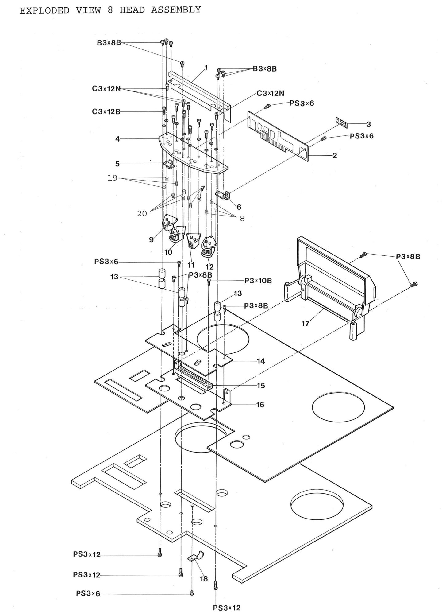 ⤢ zoomEXPLODED VIEW 8 HEAD ASSEMBLY: the head mount base with its four head stacks and springs, the head guide, the head p.c. board with its protector, brackets and connector, the shield plate, and the head housing on its base plate
PARTS LIST 9 REEL ASSEMBLY↑ TOP
| Ref. No. | Description | Part No. | Notes |
|---|---|---|---|
| 9-1 | Drum, Brake | KW0A012 | |
| 9-2 | Pin, Brake, ø3×16 | (F63316) | Ass'y KW-4J-A |
| 9-3 | Band, Brake | (KW0D015) | Ass'y KW-4J-A |
| 9-4 | Felt, Brake | (KW0D016) | Ass'y KW-4J-A |
| 9-5 | Retaining Ring, E Type ø3 | F753 | Ass'y KW-4J-A |
| 9-6 | Arm, Brake | (KW0D014) | Ass'y KW-4J-A |
| 9-7 | Retaining Ring. E Type ø2 | F752 | |
| 9-8 | Pin, Brake Solenoid | KZ5A003 | |
| 9 | Cushion, Brake Solenoid | PZ1C022 | |
| 10 | Solenoid, Brake | GP1F02 | |
| 11 | Clamp, Brake | KZ3A047 | |
| 12 | Retainer, Brake | KW4B001 | |
| 13 | Spring, Brake | GS1024 | |
| 14 | P.C, Board, Capacitor | (PB9A179) | PB-73R Ass'y |
| 15 | Capacitor, Reel Motor 6.5µF | (CZ10023W) | PB-73R Ass'y |
| 16 | Plate, R. Reel Motor | KW0G012 | |
| 17 | Plate, L. Reel Motor | KW0G013 | |
| 18 | Plate, R. Capacitor | KW4B004 | |
| 19 | Plate, L. Capacitor | KW4B003 | |
| 20 | Motor, Reel | MR1C012 | |
| 21 | Bracket, Reel Motor | KW0G016 | |
| 22 | Drum, Reel | KW0B017 | |
| 23 | Nails, Reel Drive | KW0E038 | |
| 24 | Reel Table | KW4J002 |
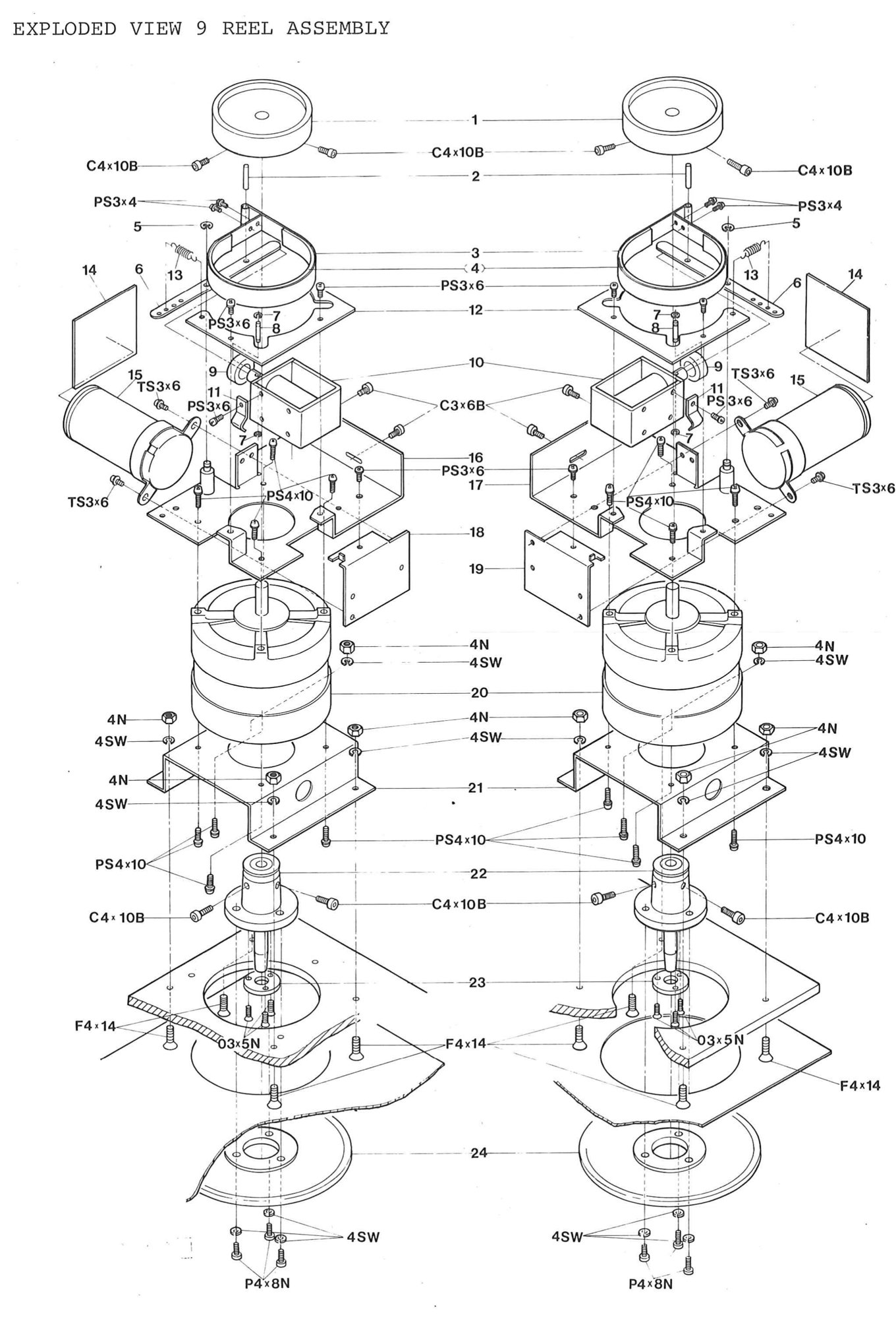 ⤢ zoomEXPLODED VIEW 9 REEL ASSEMBLY: the supply and take-up reel assemblies side by side: reel tables and reel drums, the brake drums, bands, arms and solenoids, and the reel motors with their brackets, plates and capacitors
PARTS LIST 10 COUNTER ASSEMBLY↑ TOP
| Ref. No. | Description | Parts No. | Notes |
|---|---|---|---|
| 10-1 | Switch, Push | WH12023 | |
| 10-2 | Bracket, Counter | (SR8D001) | Ass'y SR-8D-A |
| 10-3 | Felt, Counter Spacer | (PZ1B028) | Ass'y SR-8D-A |
| 10-4 | Belt, Counter | BE1B147 | |
| 1--5 | Felt, Switch | PZ1B012 | |
| 10-6 | Button, Push, Switch | KN2026 | |
| 10-7 | Counter | SR8Z004 | |
| 10-8 | Escutcheon, Counter | SR8D002 |
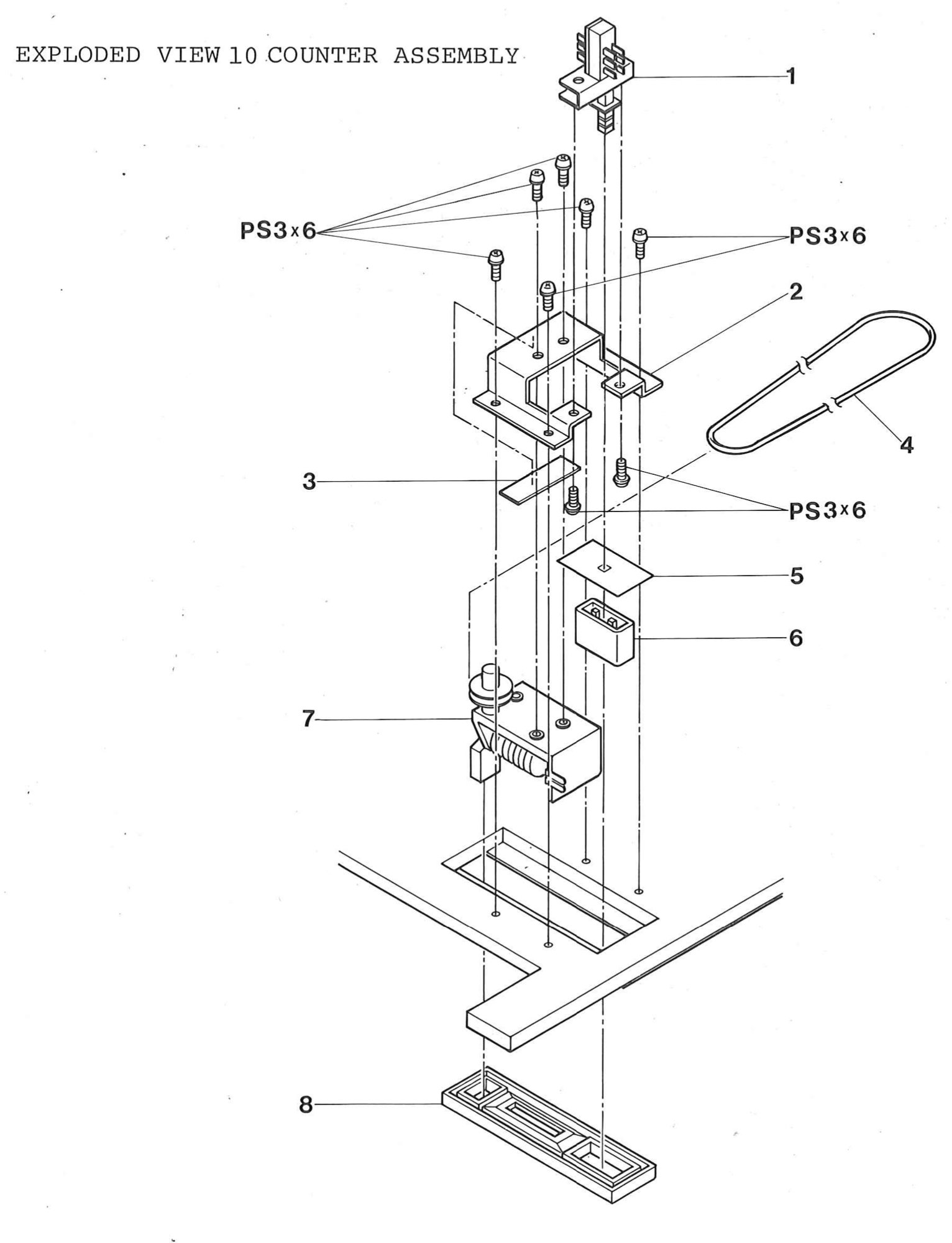 ⤢ zoomEXPLODED VIEW 10 COUNTER ASSEMBLY: the tape counter with its bracket, belt and spacer felt, the push switch with its button and felt, and the counter escutcheon
PARTS LIST 11 CONTROL SWITCH ASSEMBLY↑ TOP
| Ref. No. | Description | Part No. | Notes |
|---|---|---|---|
| 11-1 | Switch, Micro | WH11007 | |
| 11-2 | Plate, R, Switch, Base | CB20601 | |
| 11-3 | Protector, R, Button | CB20602 | |
| 11-4 | Button, Push, A, PLAY F.FWD REWIND | KN2028 | |
| 11-5 | Button, Push, B, REC | KN2029 | |
| 11-6 | Button, Push, C, STOP | KN2030 | |
| 11-7 | P.C, Board Ass'y, Aux, Switch | PB-42F | |
| 11-8 | Stud, Power P.C, Board | KZ7B106 | |
| 11-9 | P.C, Board Ass'y, Power Switch | PB-42E | |
| 11-10 | Plate, L, Switch Base | PB41A01A | |
| 11-11 | Protector, L, Button | CB20701 | |
| 11-12 | Button, Push Power | KN2031 |
The following list is for the MX5050B-2H,2L,and 4L models.
| 11-7 | P.C.Board Ass'y Aux Switch | PB-42L | |
| 11-9 | P.C.Board Ass'y Power Switch | PB-42M |
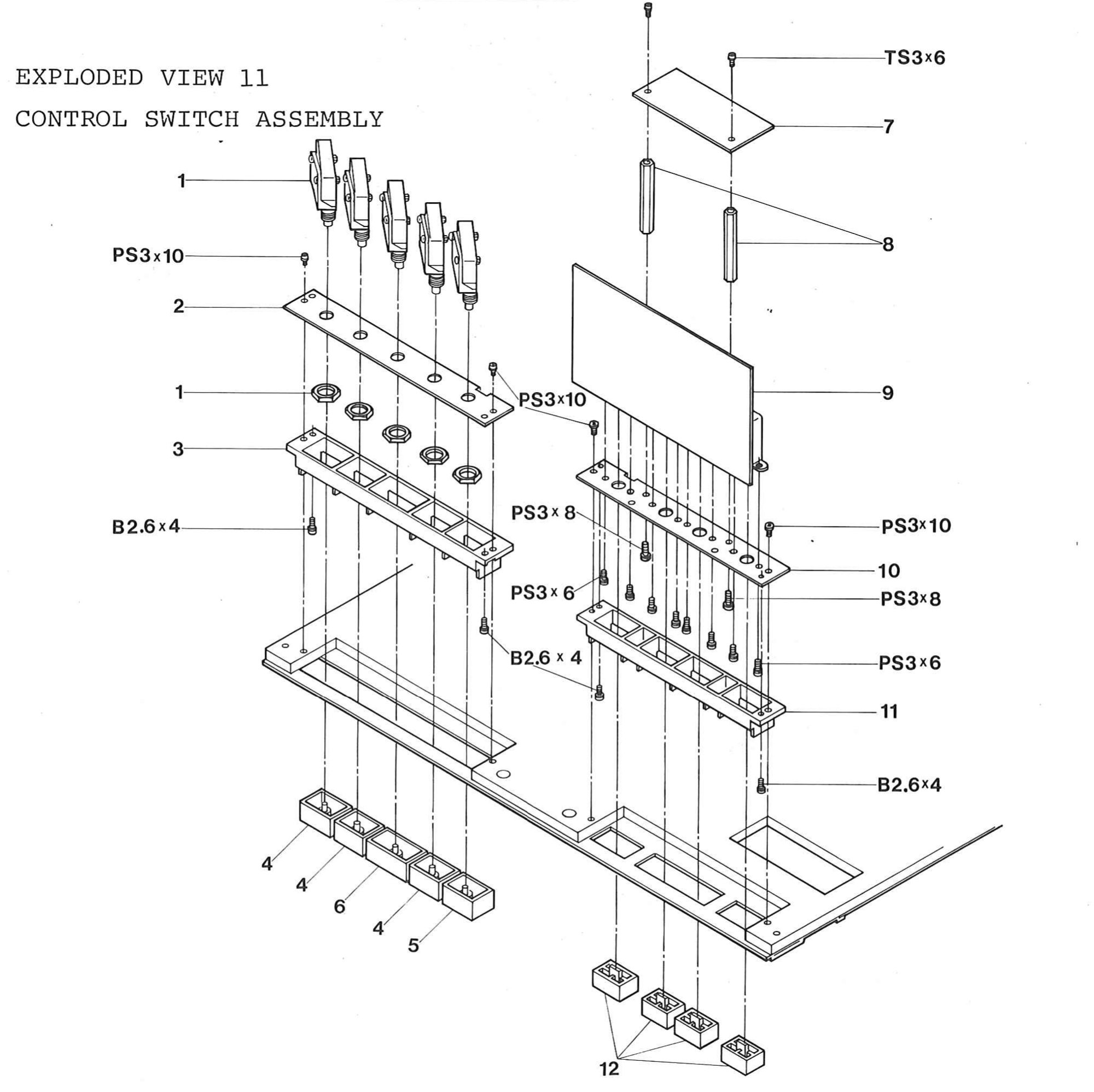 ⤢ zoomEXPLODED VIEW 11 CONTROL SWITCH ASSEMBLY: the transport pushbuttons and microswitches on their switch base plates, the auxiliary and power switch boards, protectors and studs
PARTS LIST 12 CONNECTOR PANEL ASSEMBLY↑ TOP
| Ref. No. | Description | Part No. | Notes |
|---|---|---|---|
| 12-1 | Connector, 3Soc, | CN103046 | |
| 12-2 | Connector, 3Pin, | CN103045 | |
| 12-3 | Terminal, Earth | CN901040 | |
| 12-4 | Bush, Cord | PZ1G021 | |
| 12-5 | Panel, Connector | CB70101 | |
| 12-6 | Cord, Power | PZ9D017 | |
| 12-7 | Connector Ass'y, Remote | CN7C-006 | |
| 12-8 | Spacer, Cord Bush | KZ6C025 | |
| 12-9 | Stud, P.C Board, Output | KZ7A131 | |
| 12-10 | P.C, Board Ass'y, Output, Transformer | PB-73E |
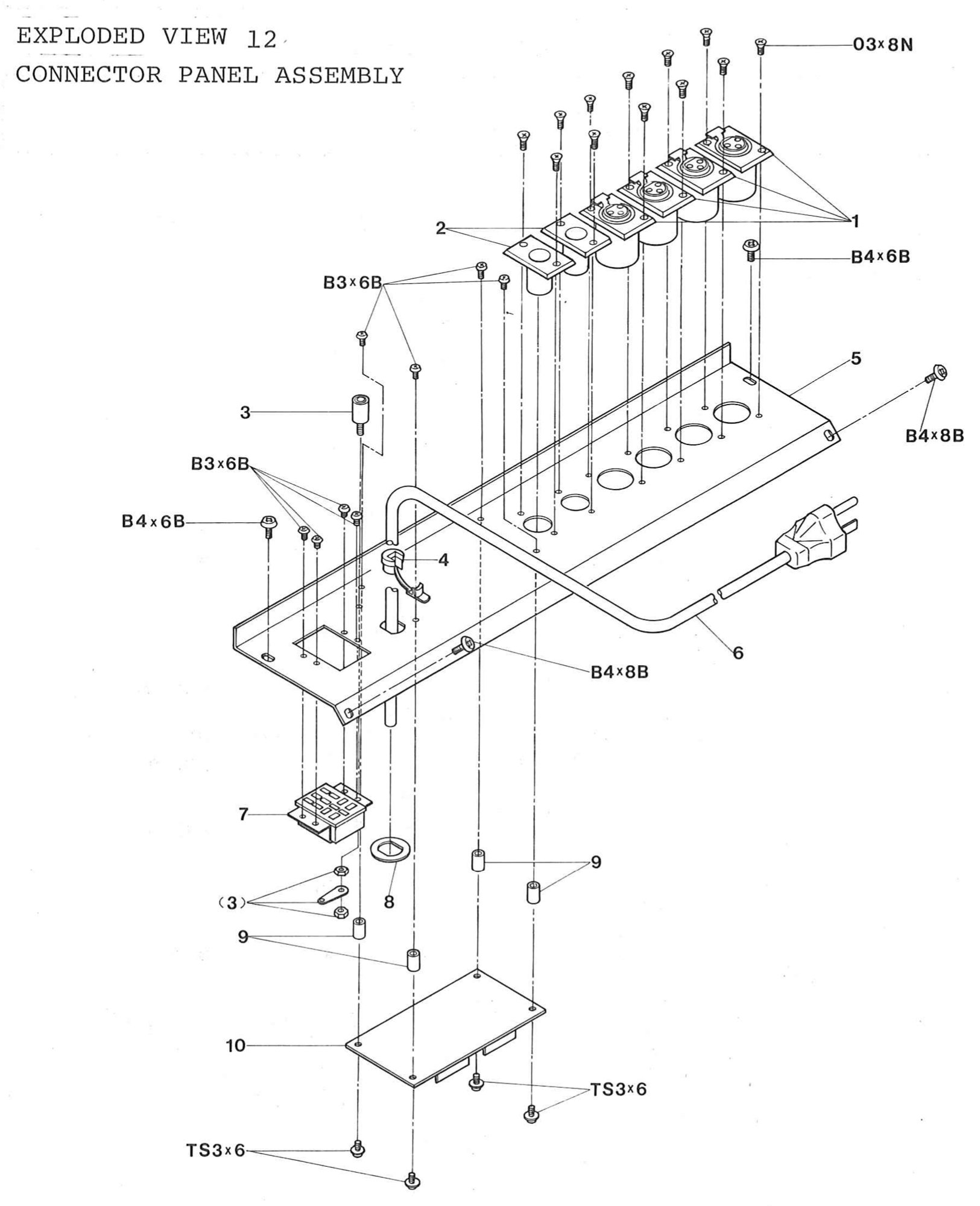 ⤢ zoomEXPLODED VIEW 12 CONNECTOR PANEL ASSEMBLY: the connector panel with its three-socket and three-pin connectors, earth terminal, power cord and bush, remote connector, and the output transformer board on its studs
PARTS LIST 13 CHASSIS ASSEMBLY↑ TOP
| Ref. No. | Description | Parts No. | Notes |
|---|---|---|---|
| 13-1 | Protector, Reel | KWOH007 | |
| 13-2 | Shaft, Tape Guide | KG6E003 | |
| 13-3 | Panel, Trim, Transport | (T506102)*1 | Ass'y T5061-A |
| NOTE*1 | Escutcheon, Pitch Control | (KC4H005)*1 | Ass'y T5061-A |
| Escutcheon, Counter | (SR8D002)*1 | Ass'y T5061-A | |
| Escutcheon, Cue | (KR4B006)*1 | Ass'y T5061-A | |
| 13-3 | Panel, Tape Transport | (T506301)*2 | Ass'y T5063-A |
| NOTE*2 | Eseutcheon, Counter | (SR8D002)*2 | Ass'y T5063-A |
| Escutcheon, Cue | (KR4B006)*2 | Ass'y T5063-A | |
| 13-4 | Panel, Trim, Control | T506103 | |
| 13-5 | Panel, Chassis, Transport | T506101 | |
| 13-6 | Cramp, Wire | KZ3A022 | |
| 13-7 | Stud, Frame | KZ7A215 | |
| 13-8 | Spacer, P.C, Board,LED(B) | KZ7A823 | |
| 13-9 | P.C, Board Ass'y LED.(B) | PB-81H | |
| 13-10 | Bracket, Sensing Switch | T505005 | |
| 13-11 | Switch, Sensing | WH91005 | |
| 13-12 | Belt, Sensing Switch | BE1B069 | |
| 13-13 | Transformer, Power | TF11025A | |
| 13-14 | Angle, Chassis, Rear | T506104 | |
| 13-15 | Frame, Chassis, Side | T506106 | |
| 13-16 | Plate, L, P,C,Board | T506107 | |
| 13-17 | Plate, R, P.C, Board | T506108 | |
| 13-18 | Angle, Control P.C, Board | (T506111) | Ass'y T5061-B |
| 13-19 | Cushion, Angle | (PZ1C031) | Ass'y T5061-B |
| 13-20 | Bolt, Angle | T506109 | |
| 13-21 | Angle | KZ3A068 | |
| 13-22 | Spacer, Angle,P.C, Board | KZ7A315 | |
| 13-23 | P.C, Board Ass'y, Control | PB-42D | |
| 13-24 | Protector, P.C, Board | T506114 | |
| 13-25 | Washer, Trim, Panel | KZ6C010 | |
| 13-26 | Washer, Vinyl, Panel | KZ6C011 |
NOTE: *1; For dc servo version:MX-5050B-2HD, 2LD, 4LD, FHD, and FLD.
*2; For synchronous version:MX-5050B-2H, 2L, and 4L.
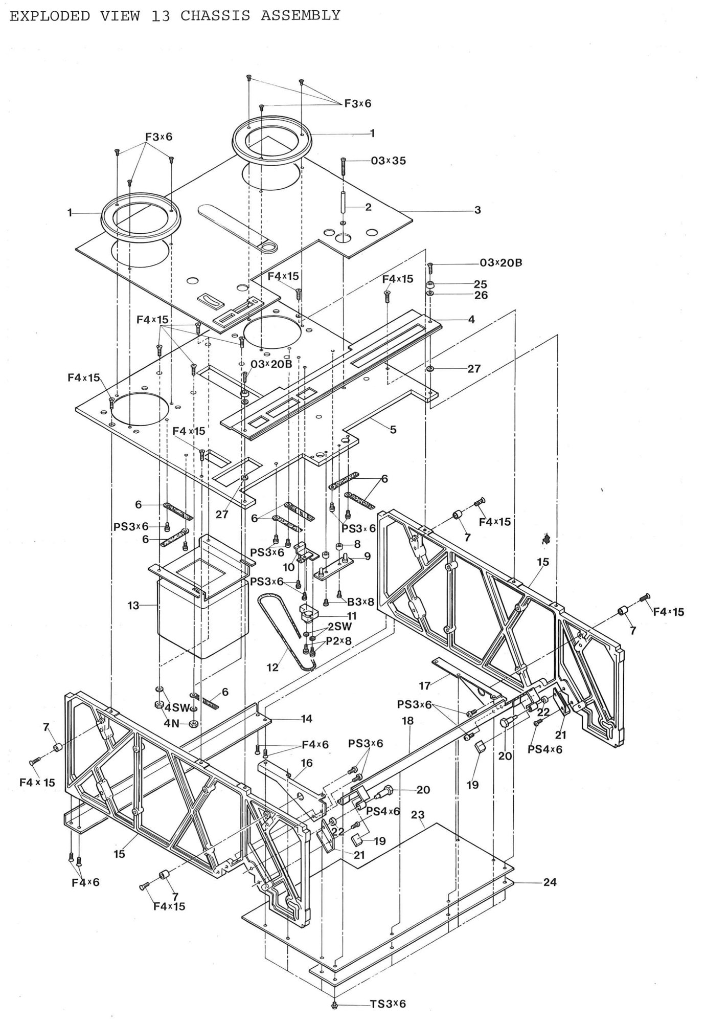 ⤢ zoomEXPLODED VIEW 13 CHASSIS ASSEMBLY: the transport trim and chassis panels, the reel protectors and tape guide shaft, the side frames and rear angle, the power transformer, the sensing switch, the LED board (B), and the control p.c. board with its angle, plates and protector
PARTS LIST 14 AMPLIFIER ASSEMBLY↑ TOP
| Ref. No. | Description | Parts No. | Notes |
|---|---|---|---|
| 14-1 | Knob,A.upper,Amp | KN1014 | |
| 14-2 | Knob. B. Lower, Amp | KN1015 | |
| 14-3 | Washer, Knob, Amp | KZ6C017 | |
| 14-4 | Button, Push, Red, Amp | KN2025 | |
| 14-5 | Button, Push, Black | KN2026 | |
| 14-6 | Button, Push, Gry | KN2027 | |
| 14-7 | Panel, Trim, Amp | (A102801) | Ass'y A1028-A |
| 14-8 | Escutcheon, Meter | (PZ4A007) | Ass'y A1028-A |
| 14-9 | Meter, VU | ME11005 | |
| 14-10 | Felt, Shield, VU Meter | PZ1B013 | |
| 14-11 | P.C, Board Ass'y. LED(E) | PB-81L | |
| 14-12 | P.C, Board Ass'y. LED(D) | PB-81K | |
| 14-13 | Felt, Push Switch | PZ1B012 | |
| 14-14 | Panel, Chassis, Amp. | A102802 | |
| 14-15 | Resistor, Var, Amp | RV224010 | |
| 14-16 | Jack, Stereo | CN603009 | |
| 14-17 | Switch, Slide | WH340013 | |
| 14-18 | P.C, Board Ass'y, LED(C) | PB-81J | |
| 14-19 | P.C, Bord Ass'y, VU Amp | PB-13K | |
| 14-20 | P.C, Board Ass'y, Amplifier | PB-13J | |
| 14-21 | P.C, Board Ass'y, Rec, EQ | PB-81Q | |
| 14-22 | Angle, P.C, Board Rec, EQ | KZ3A072 | |
| 14-23 | Frame, L. Chassis, Amp | A102808 | |
| 14-24 | Frame, R. Chassis, Amp | A102807 | |
| 14-25 | Pivot | A102809 | |
| 14-26 | Bracket, P.C, Board, Amp | A102803 | |
| 14-27 | Felt, Slide, Switch | PZ1B010 |
For MX5050B-4L, 4LD↑ TOP
| 14-20 | P.C.Board Ass'y Amplifier | PB-13Z |
For MX5050B-FHD,FLD↑ TOP
| 14-7 | Panel, Trim, Amp | (A103301) | Ass'y A1033-A |
| 14-8 | Escutcheon, Meter | (PZ4A007) | Ass'y A1033-A |
| 14-12 | P.C.Board Ass'y LED(F) | PB-81T | |
| 14-20 | P.C.Board Ass'y Amplifier | PB-13X | |
| 14-21 | P.C.Board Ass'y Rec. EQ. | PB-81S |
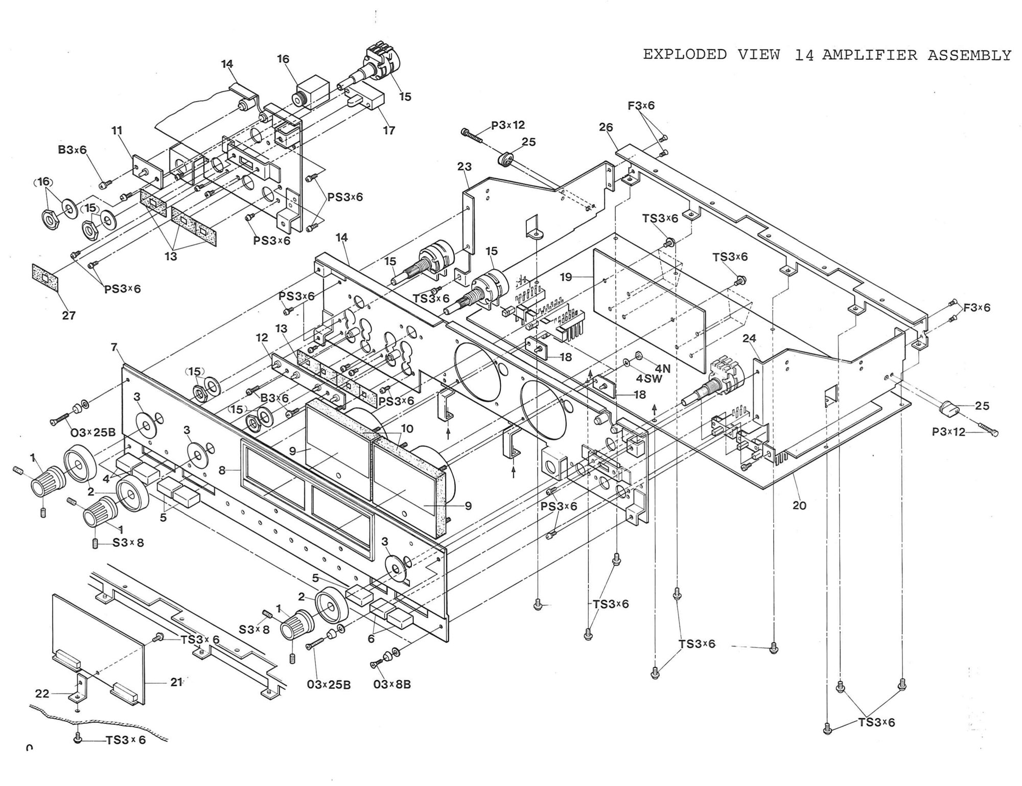 ⤢ zoomEXPLODED VIEW 14 AMPLIFIER ASSEMBLY: the amplifier's knobs, push buttons, trim panel and meter escutcheon, the VU meters and LED boards, the chassis panel and frames with the pivot, the headphone jack, slide switch and potentiometer, and the amplifier, VU amp and record EQ boards, turned here to read across the page
PARTS LIST 15 PACKAGING↑ TOP
| Ref. No. | Description | Part No. | Notes |
|---|---|---|---|
| 15-1 | Plate, TOP | K703126 | |
| 15-2 | Packing, L. Side | K703103 | |
| 15-3 | Packing, R. Side | K703102 | |
| 15-4 | Plate, Manual Hold | K703124 | |
| 15-5 | Accessory, Hold Down Knob | KWOHA | |
| 15-6 | Accessory, Operation, Manual | OS1-011 | |
| 15-7 | Accessory, Reel. Open | ZA-51A | |
| 15-8 | Plate, Spacing, Reel Box | K703123 | |
| 15-9 | Cover, Tape Recorder | PZ9C003 | |
| 15-10 | Packing, Bottom | K703104 | |
| 15-11 | Case, Packing | K703101 |
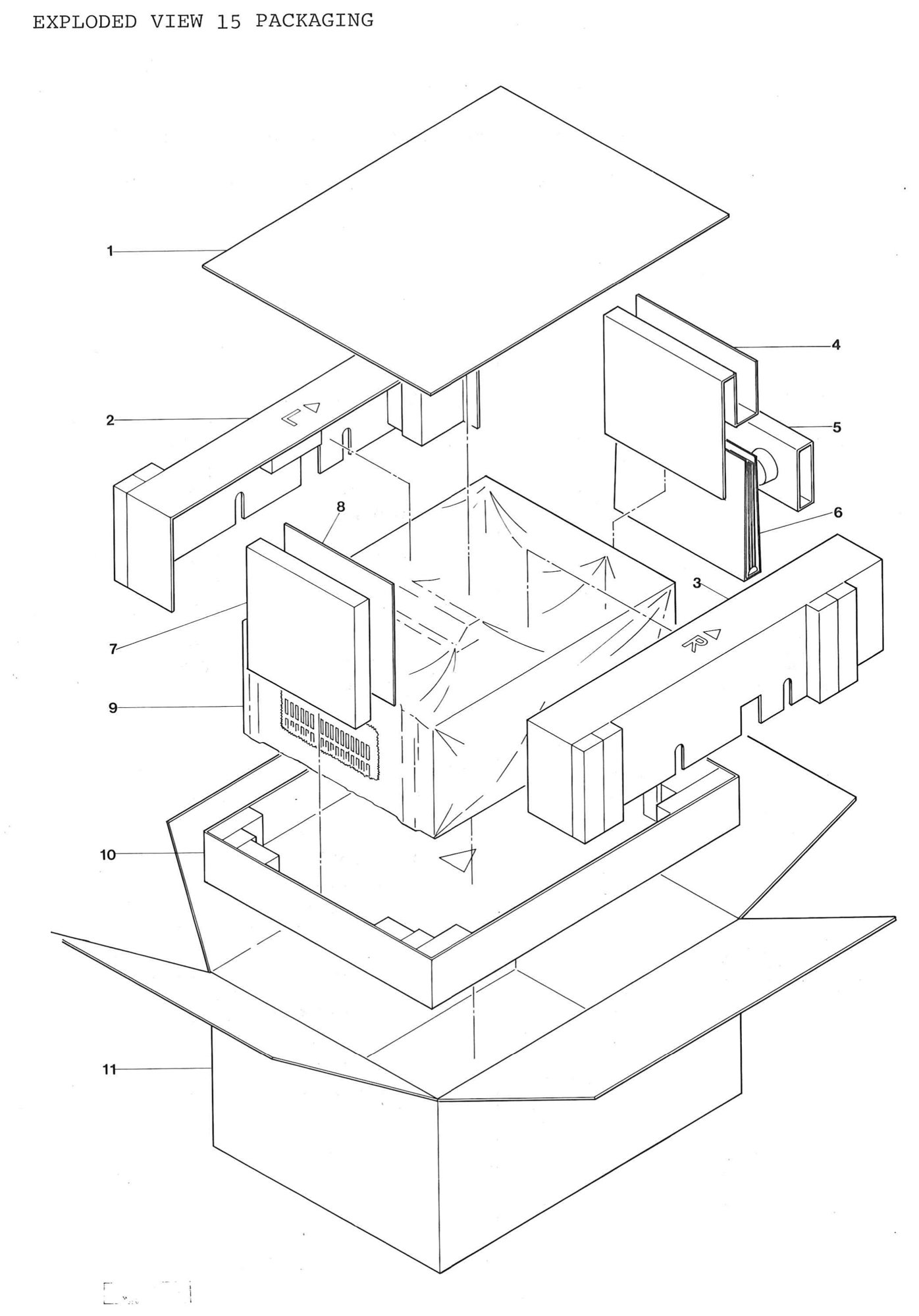 ⤢ zoomEXPLODED VIEW 15 PACKAGING: the recorder in its cover between the side and bottom packings, with the top plate, the manual hold plate, the operation manual, hold down knob and reel accessories, inside the packing case
PIN IDENTIFICATION↑ TOP
Following table shows the pin identification of all diodes, transistors, and integrated circuits (ICs), used in the circuits of this equipment.
DIODES↑ TOP
| D-1 | PNS2VB20 | (S2VB20) |
| D-2 | PN-0038 | (RD12EB3) |
| D-3 | PNSM1-02 | (SM1-02) |
| D-4 | PN1S953 | (1S953) |
| D-5 | PN-0003 PN-0002 | (SEL103S) (SEL303E) |
TRANSISTORS↑ TOP
| Tr-1 | QC945LK QA733P QC1222EA QC2003K | (2SC945LK) (2SA733P) (2SC1222(2)EA) (2sc2003K) |
| Tr-2 | Q2SK68AN | (2SK68AN) |
| Tr-3 | QD571L | (2SD571L) |
| Tr-4 | QC1583G QA798G | (2SC1583G) (2SA798G) |
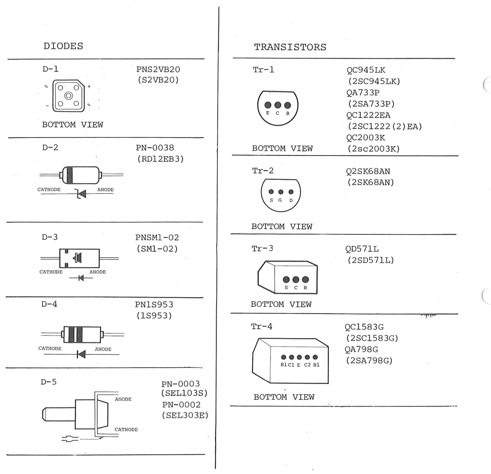 ⤢ zoomPIN IDENTIFICATION: the outline and pin order of each diode and transistor type: D-1 and Tr-1 to Tr-4 from below, D-2 to D-5 from the side with cathode and anode marked
ICs↑ TOP
| IC-1 | IM54410P | (M54410P) |
| IC-2 | IA00N IA03N | (SN7400N) (SN7403N) |
| IC-3 | I9602PC | (9602PC) |
| IC-4 | IHC571C | (µPC571C) |
| IC-5 | IHC14305 IHC14324 IHC14315 | (µA7805UC or µPC14305H) (µA7825UC or µPC14324H) (µA7815UC or µPC14315H) |
| IC-6 | [IC704] II15UC | (µA7915UC) |
| IC-7 | I-0004 | (NE5534AN) |
| IC-8 | I-0001 | (NJM4559DE) |
| IC-9 | IA14N | (SN7414N) |
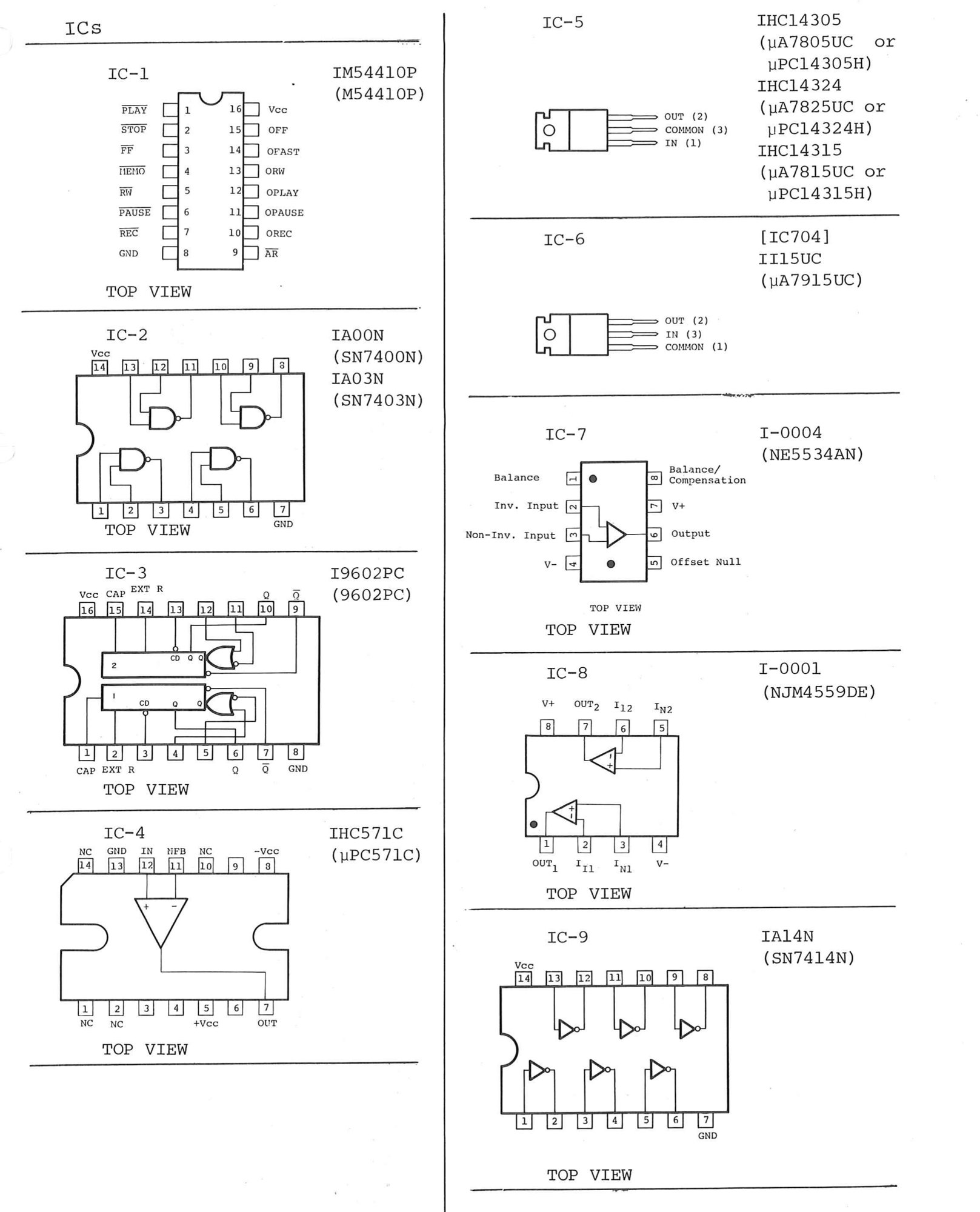 ⤢ zoomICs: the pin-outs of IC-1 to IC-9: the transport control logic, gates, one-shots, inverters and op-amps from the top, and the regulators as package outlines with their pins named
BLOCK DIAGRAM ( for 2 track type )↑ TOP
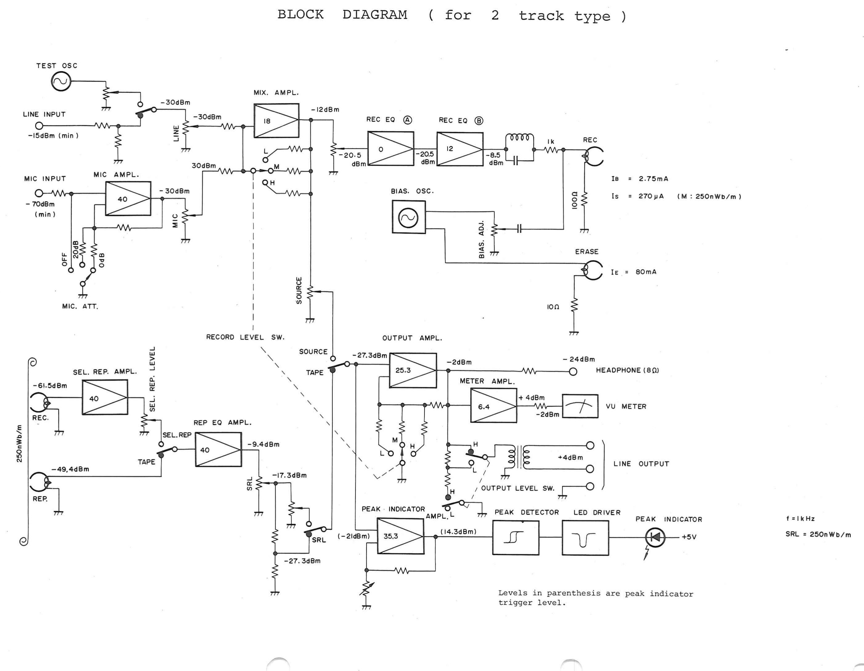
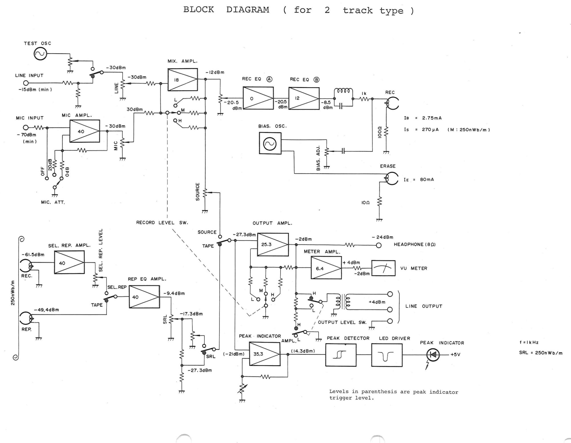 ⤢ zoomBLOCK DIAGRAM ( for 2 track type ): the signal path from line, mic and test oscillator inputs through the mix, record EQ and bias stages to the record and erase heads, and back from the reproduce heads through the reproduce, output, meter and peak indicator amplifiers, with levels marked at each stage
Full-resolution scan of this sheet — 2807 × 2178 px, 0.3 MB.
BLOCK DIAGRAM ( for 4 track type )↑ TOP
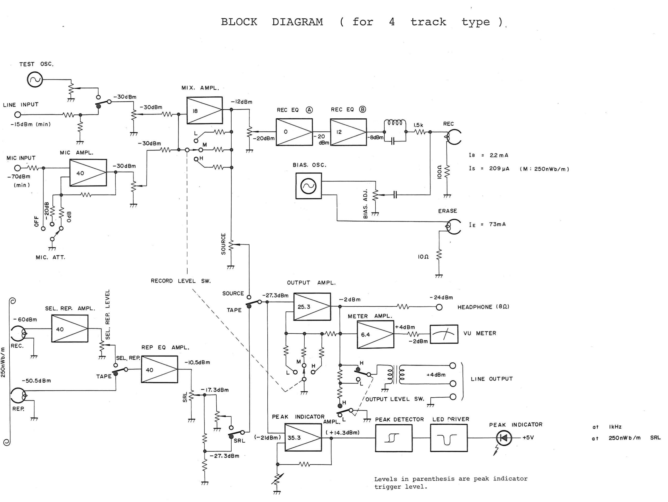
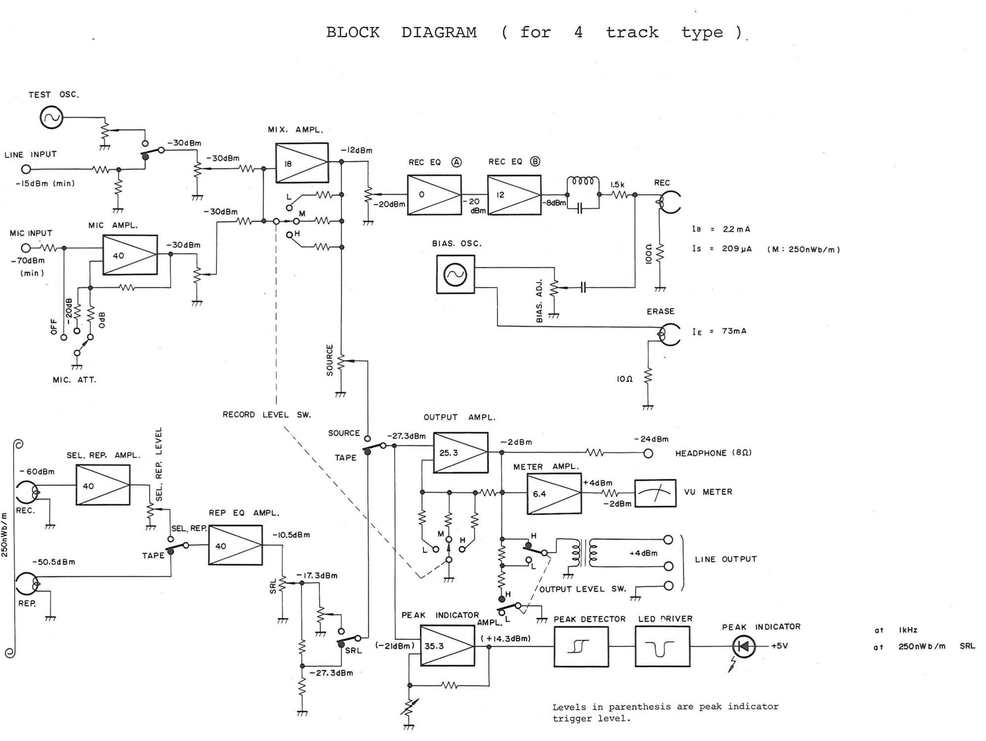 ⤢ zoomBLOCK DIAGRAM ( for 4 track type ): the same signal path drawn for the four-track heads, with its own head currents and levels
Full-resolution scan of this sheet — 2763 × 2078 px, 0.3 MB.
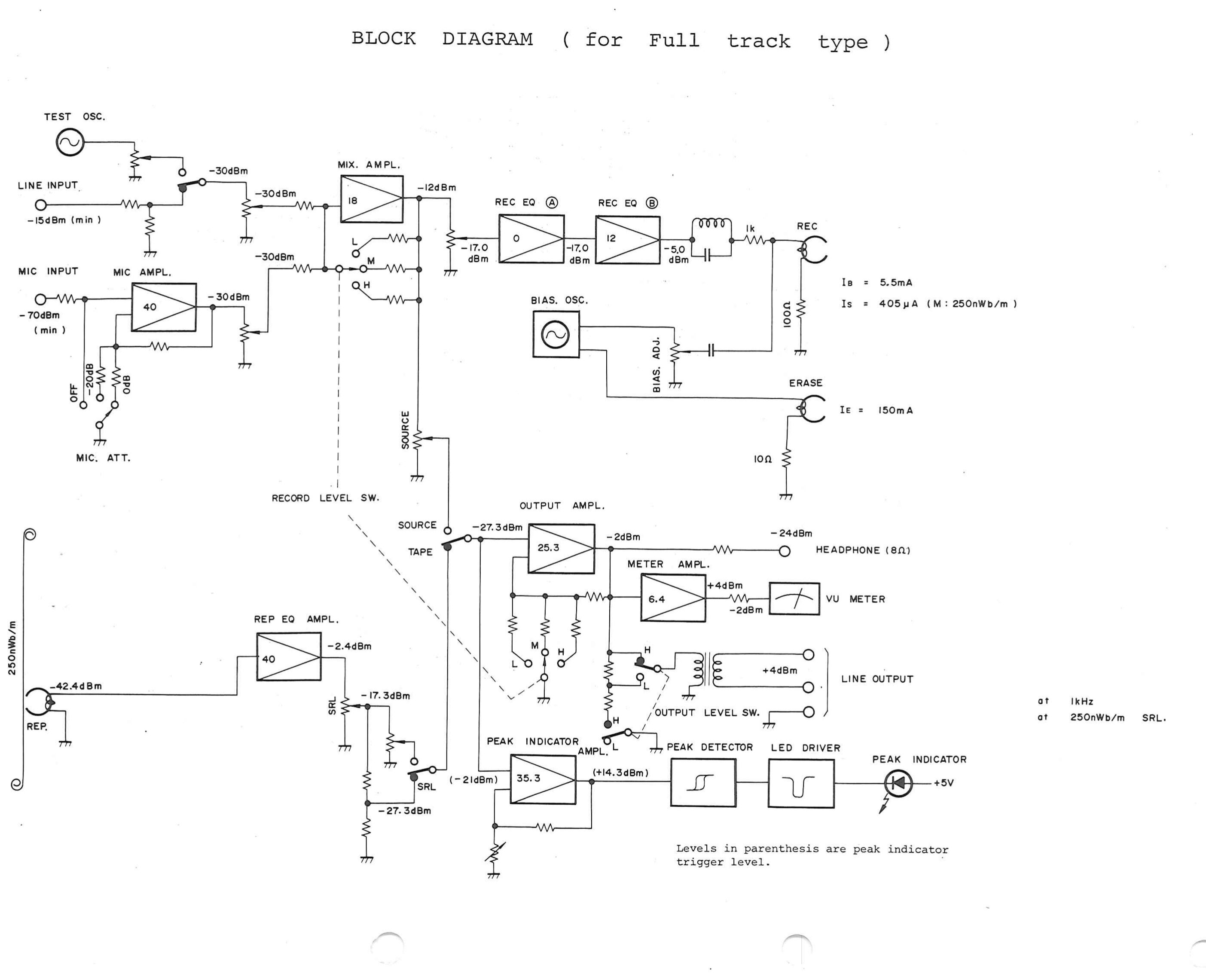
BLOCK DIAGRAM ( for Full track type )↑ TOP
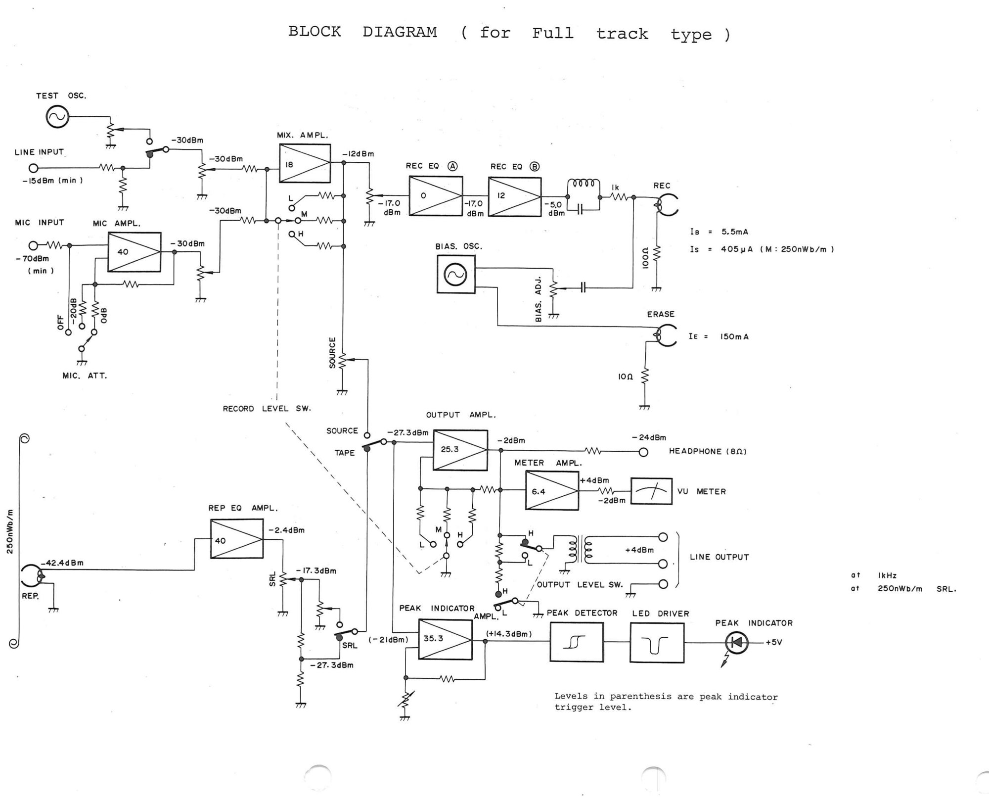 ⤢ zoomBLOCK DIAGRAM ( for Full track type ): the same signal path drawn for the full-track heads, without the selective reproduce amplifier
Full-resolution scan of this sheet — 2807 × 2281 px, 0.3 MB.
HEAD ASSEMBLY↑ TOP
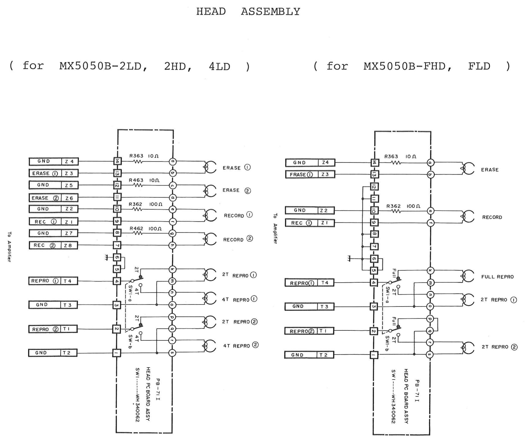 ⤢ zoomHEAD ASSEMBLY: the head p.c. board wiring, for the MX5050B-2LD, 2HD and 4LD at left and for the MX5050B-FHD and FLD at right, from the connector pins through the head selector switches to the erase, record and reproduce heads
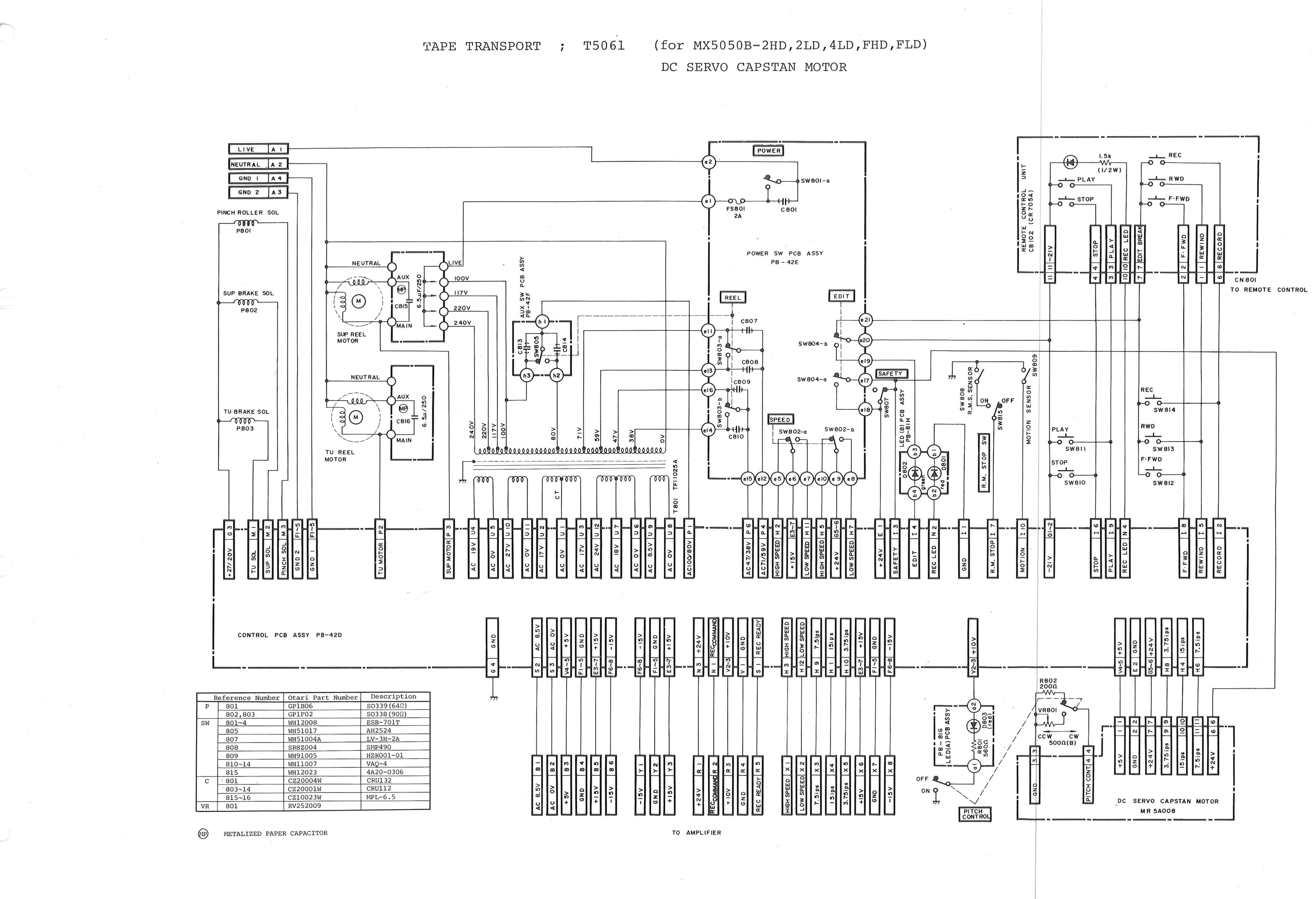
TAPE TRANSPORT ; T5061 (for MX5050B-2HD,2LD,4LD,FHD,FLD) DC SERVO CAPSTAN MOTOR↑ TOP
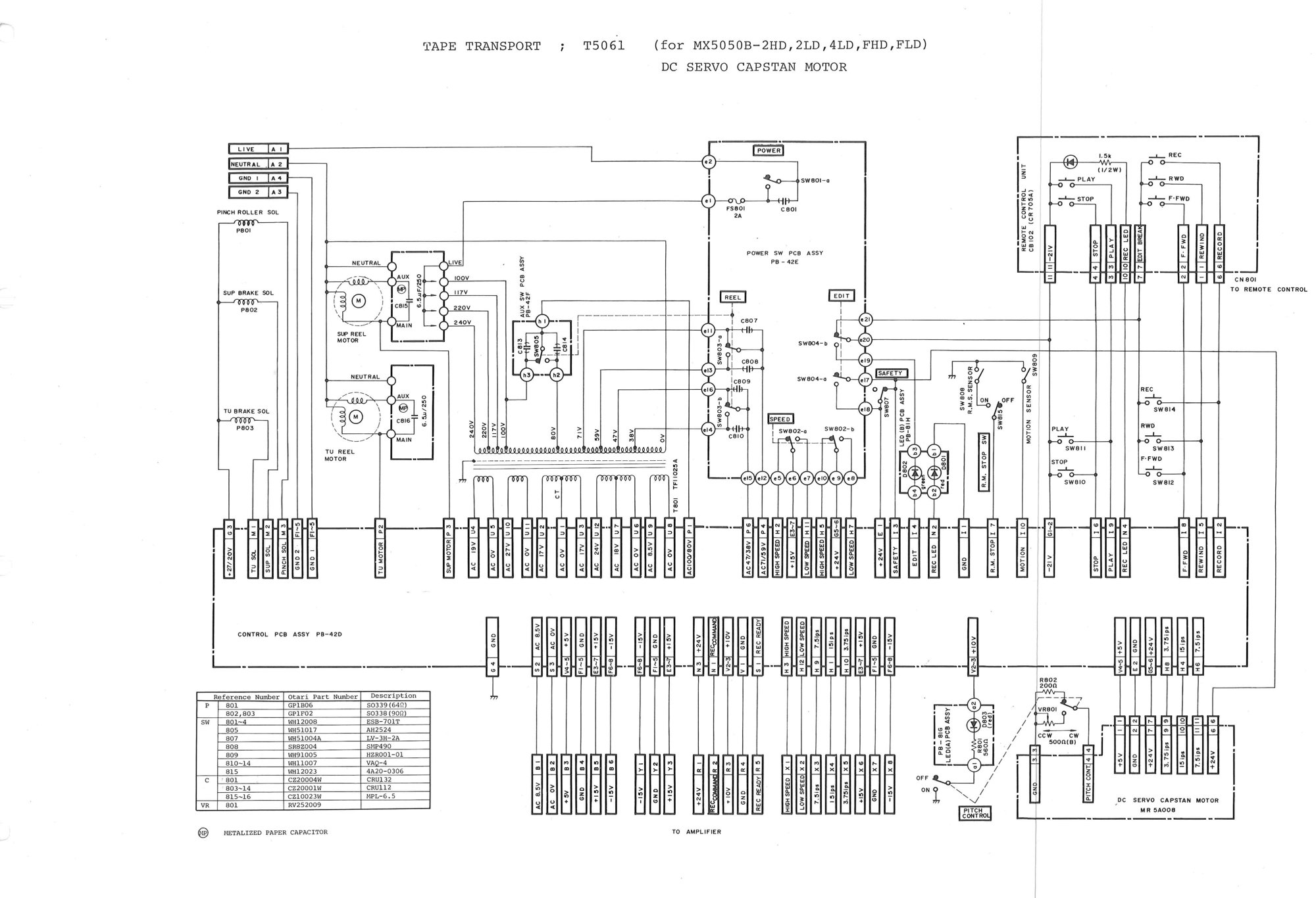 ⤢ zoomTAPE TRANSPORT ; T5061 (for MX5050B-2HD,2LD,4LD,FHD,FLD) DC SERVO CAPSTAN MOTOR: the transport wiring schematic for the dc servo models, from the control p.c.b. to the motors, solenoids, switches and connectors
Full-resolution scan of this sheet — 4664 × 3186 px, 0.9 MB.
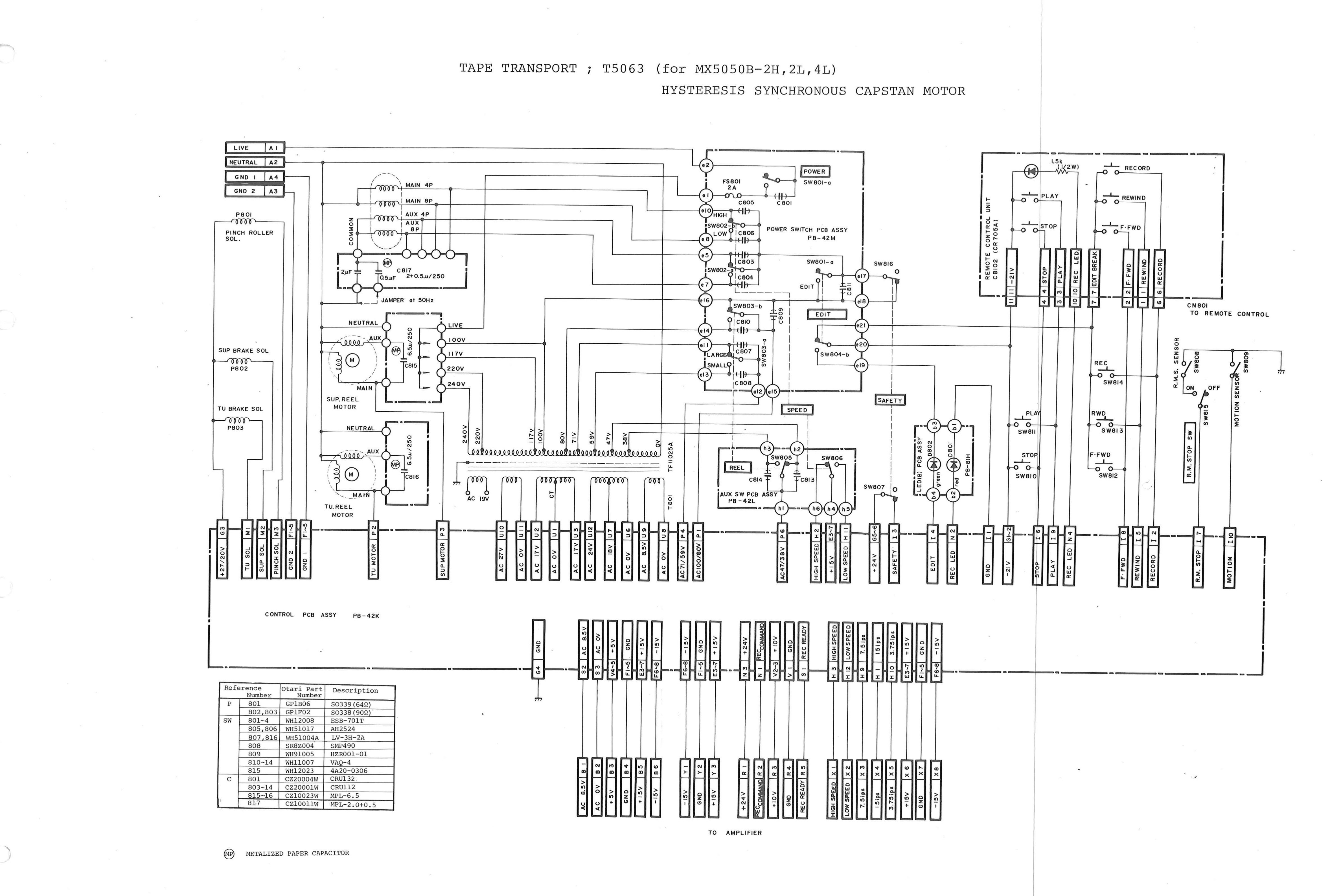
TAPE TRANSPORT ; T5063 (for MX5050B-2H,2L,4L) HYSTERESIS SYNCHRONOUS CAPSTAN MOTOR↑ TOP
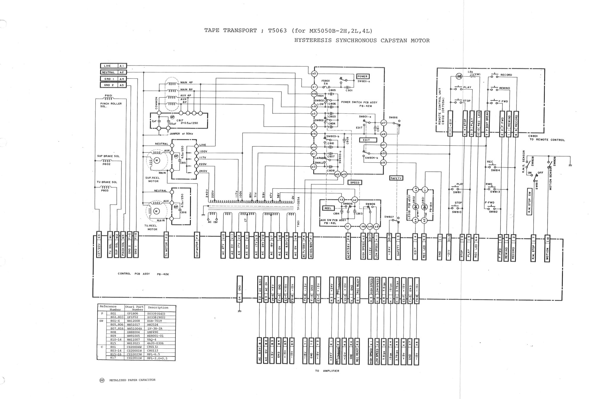 ⤢ zoomTAPE TRANSPORT ; T5063 (for MX5050B-2H,2L,4L) HYSTERESIS SYNCHRONOUS CAPSTAN MOTOR: the transport wiring schematic for the hysteresis synchronous models
Full-resolution scan of this sheet — 4713 × 3176 px, 0.9 MB.
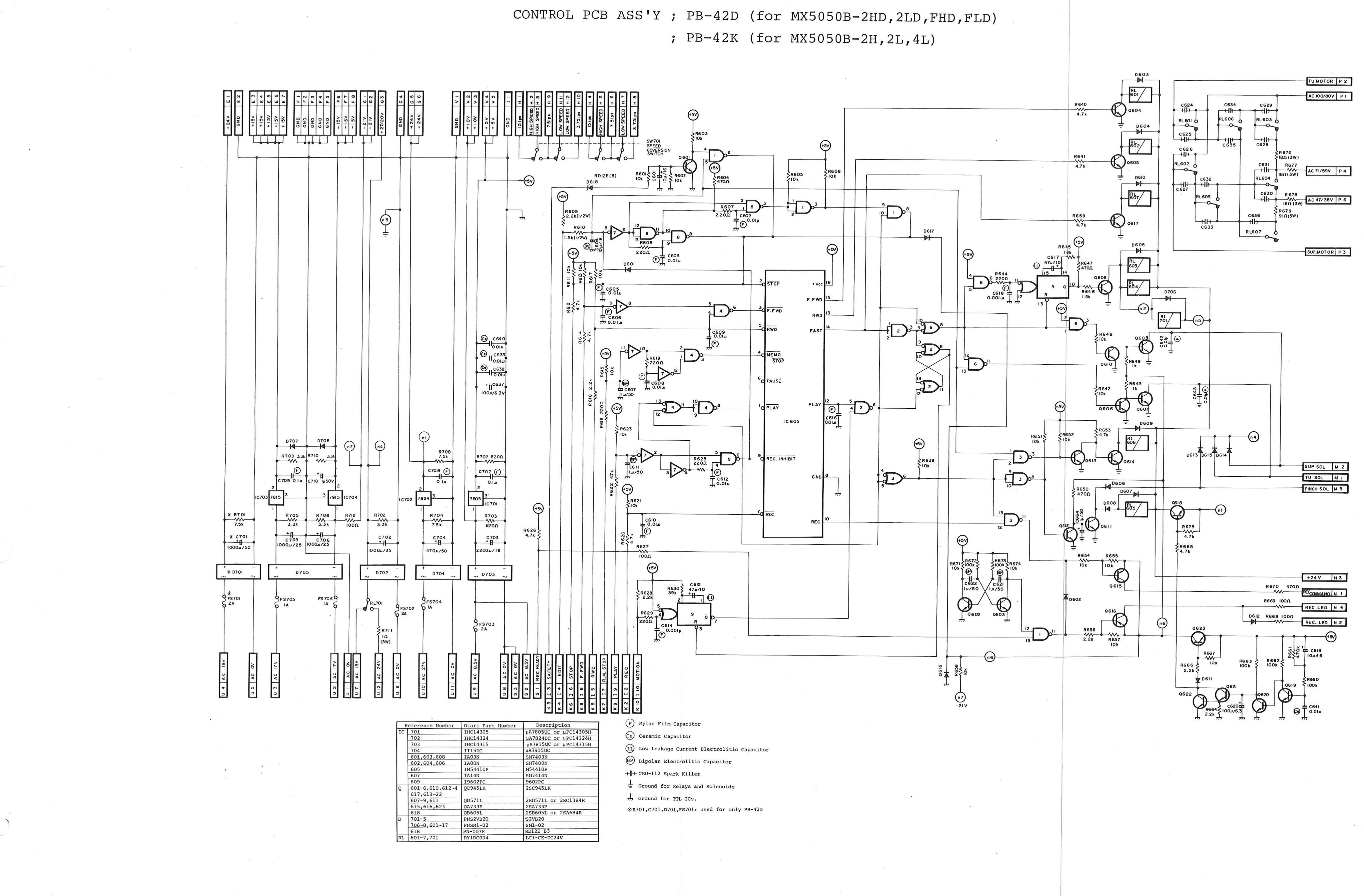
CONTROL PCB ASS'Y ; PB-42D (for MX5050B-2HD,2LD,FHD,FLD) ; PB-42K (for MX5050B-2H,2L,4L)↑ TOP
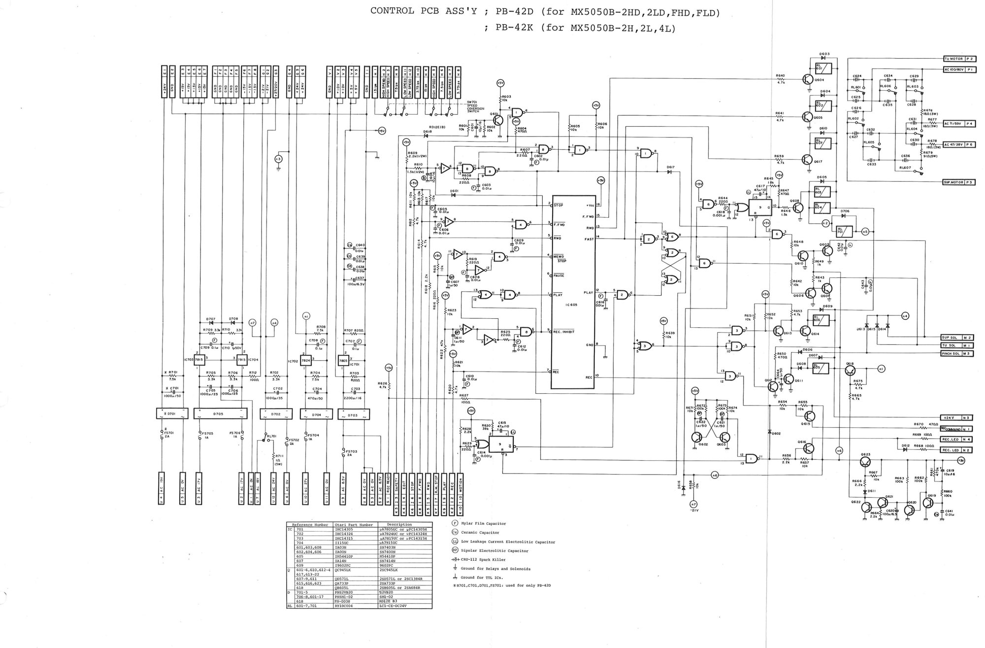 ⤢ zoomCONTROL PCB ASS'Y ; PB-42D (for MX5050B-2HD,2LD,FHD,FLD) ; PB-42K (for MX5050B-2H,2L,4L): the transport control board schematic: the logic IC, relays, solenoid drivers and power supply regulators, with its parts table
Full-resolution scan of this sheet — 4698 × 3088 px, 0.9 MB.
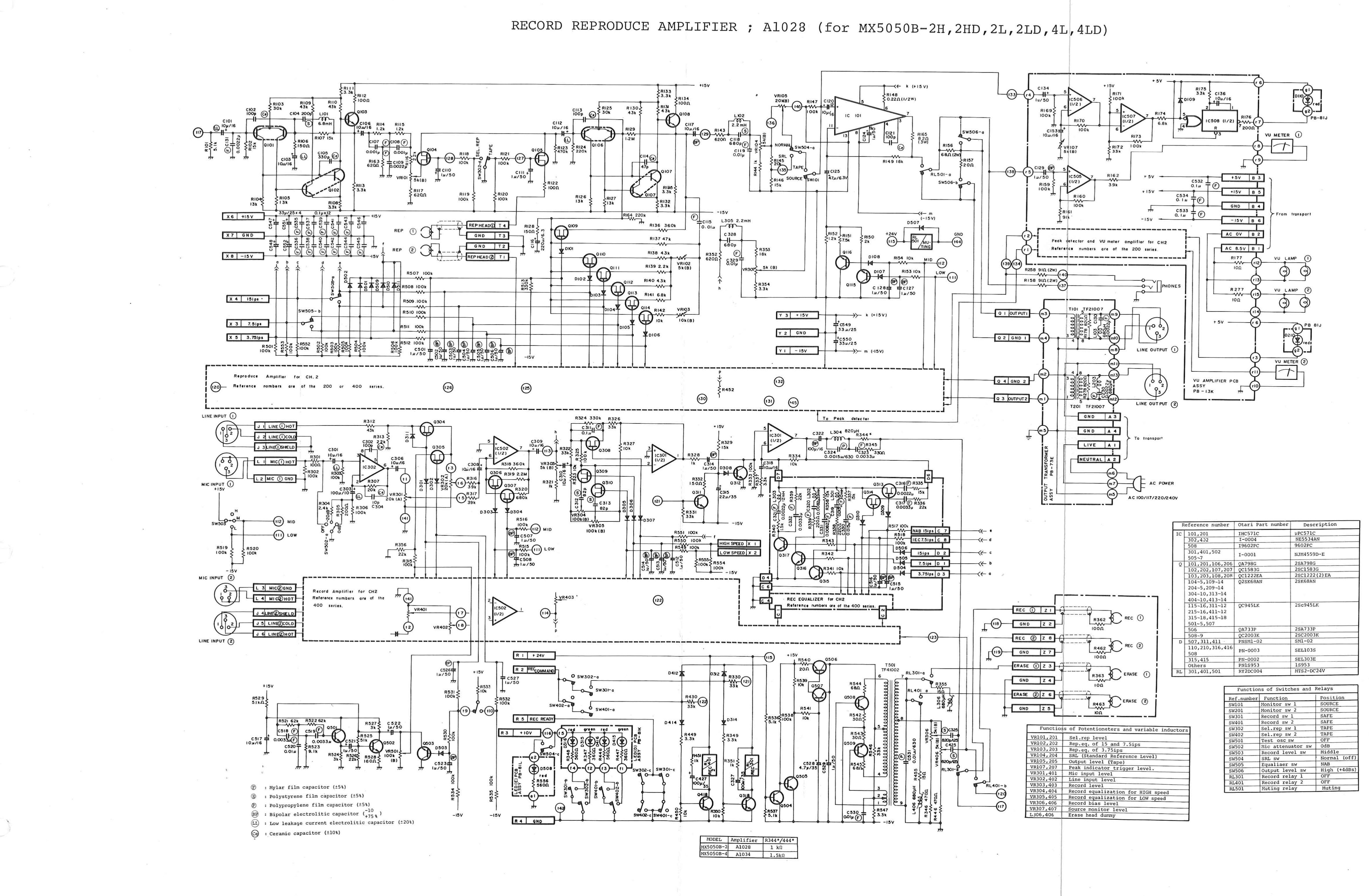
RECORD REPRODUCE AMPLIFIER ; A1028 (for MX5050B-2H,2HD,2L,2LD,4L,4LD)↑ TOP
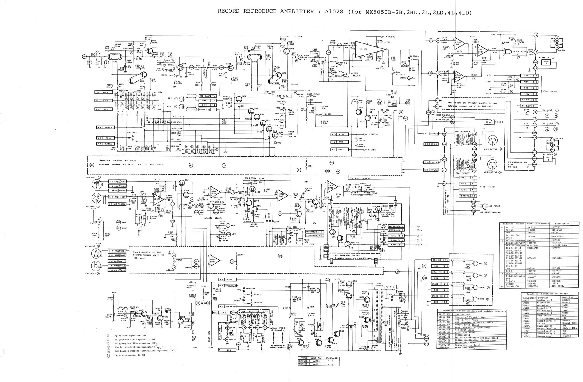 ⤢ zoomRECORD REPRODUCE AMPLIFIER ; A1028 (for MX5050B-2H,2HD,2L,2LD,4L,4LD): the record and reproduce amplifier schematic, with its tables of semiconductors, potentiometers, and switches and relays
Full-resolution scan of this sheet — 4710 × 3083 px, 1.4 MB.
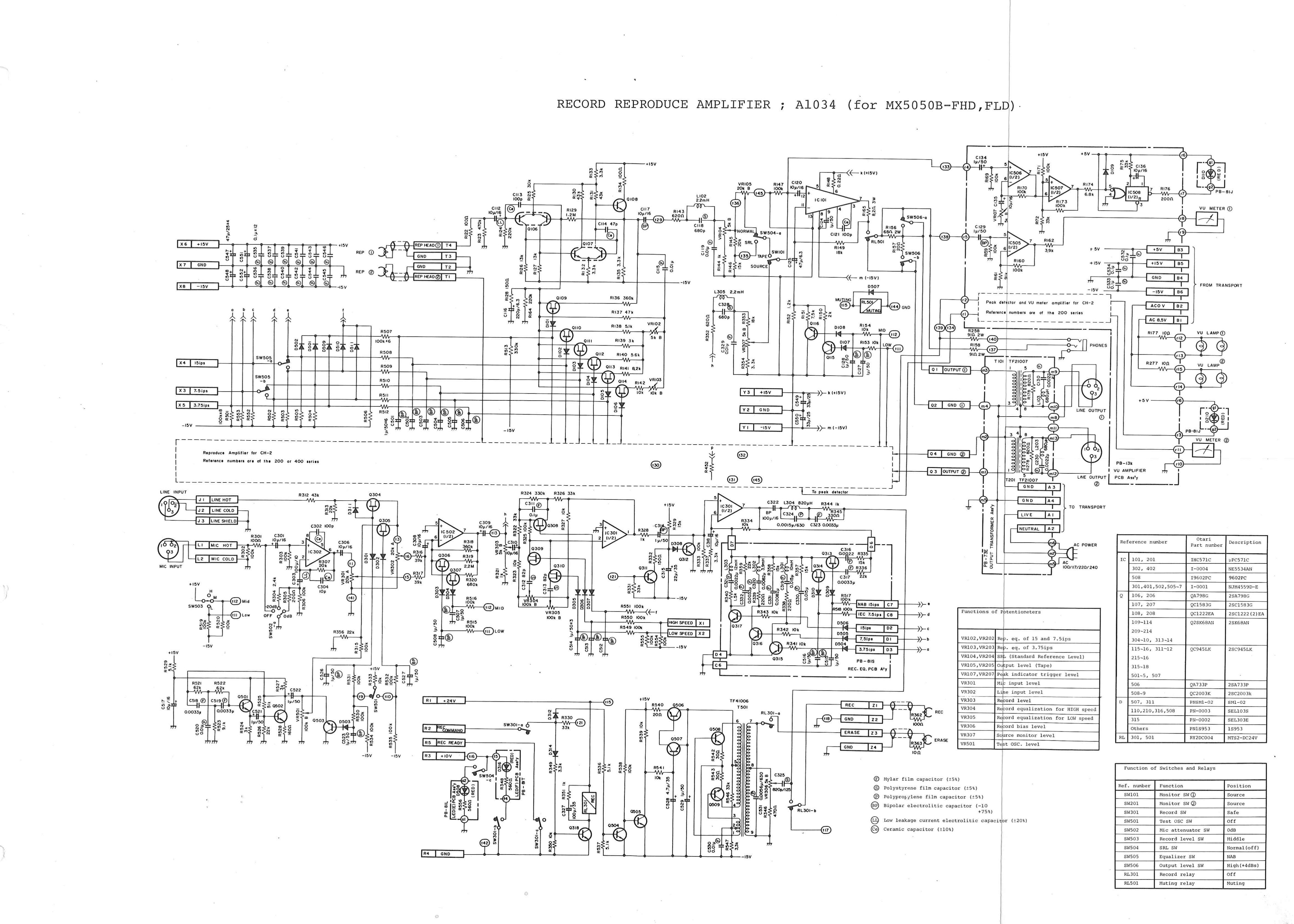
RECORD REPRODUCE AMPLIFIER ; A1034 (for MX5050B-FHD,FLD)↑ TOP
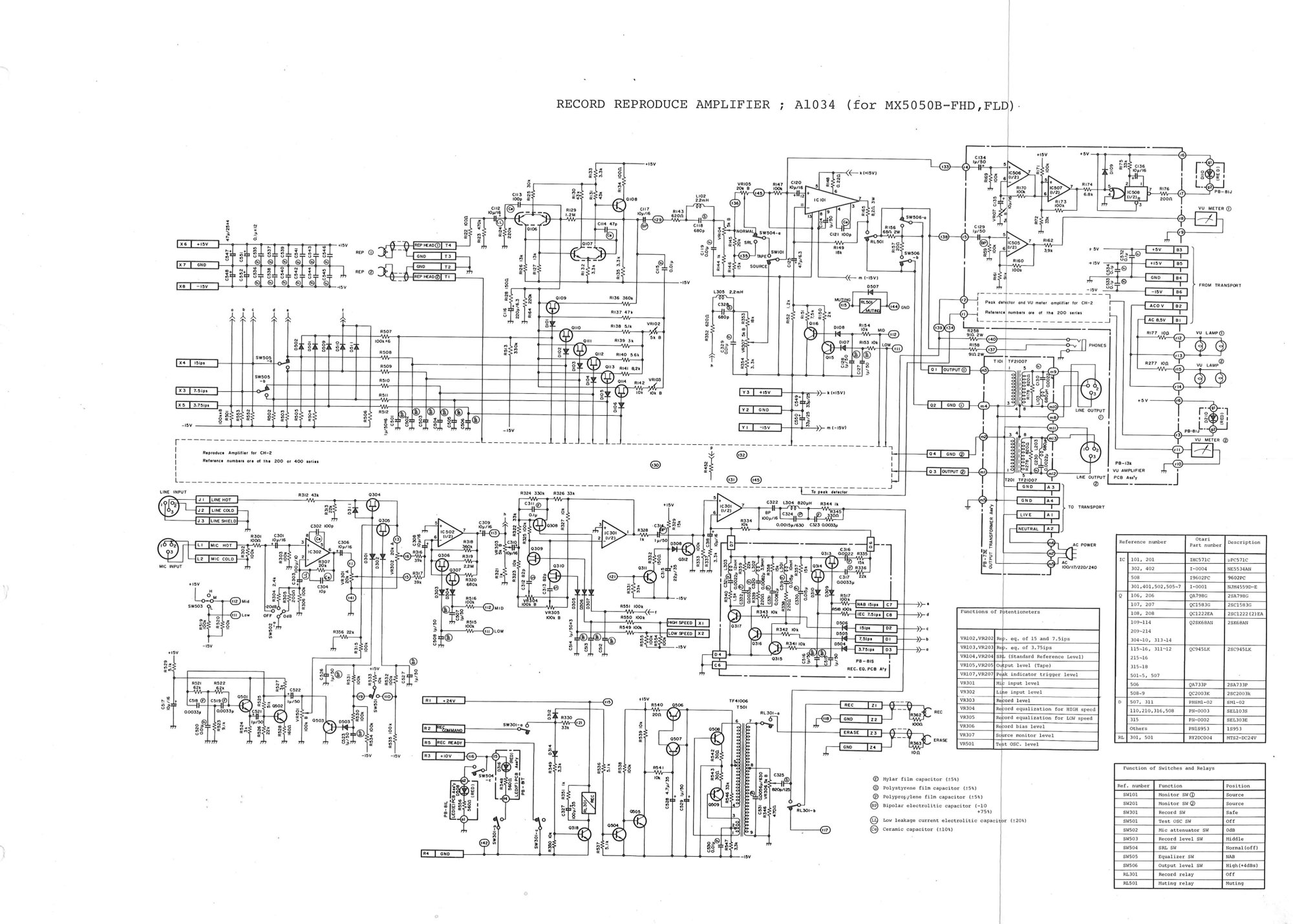 ⤢ zoomRECORD REPRODUCE AMPLIFIER ; A1034 (for MX5050B-FHD,FLD): the full-track record and reproduce amplifier schematic, with its tables of semiconductors, potentiometers, and switches and relays
Full-resolution scan of this sheet — 4714 × 3367 px, 1.3 MB.