QXD Maintenance Manual — Digital Edition · Part 6 · scan pages 51-117
View source PDF ↗Parts Lists and Schematics
Trace the listed factory numbers across MX-5050 models with the service-parts finder →
PARTS LIST 1↑ TOP
| Ref. No. | Description | Parts No. | Notes |
|---|---|---|---|
| 1-1 | Screw | EZ-09-M3x25 | |
| 1-2 | Display Washer | TY-800-021 | |
| 1-3 | Sheet | TY-800-017 | |
| 1-4 | Wood Screw | EZ-09-M3.5x20 | |
| 1-5 | Protector | CS-264-005 | |
| 1-6 | Case Top Board | CS-274-008 | |
| 1-7 | Case Side Board | CS-274-002 | |
| 1-8 | Latch | CA-39-C-15 | |
| 1-9 | Wood Screw | EZ-09-M3.1x16 | |
| 1-10 | Cap Screw | EZ-09-M4x25 | |
| 1-11 | Display Washer | TY-800-014 | |
| 1-12 | Under Cover | CS-274-005 | |
| 1-13 | Screw | EZ-09-M3x8 | |
| 1-14 | Case Bottom Board | CS-274-010 |
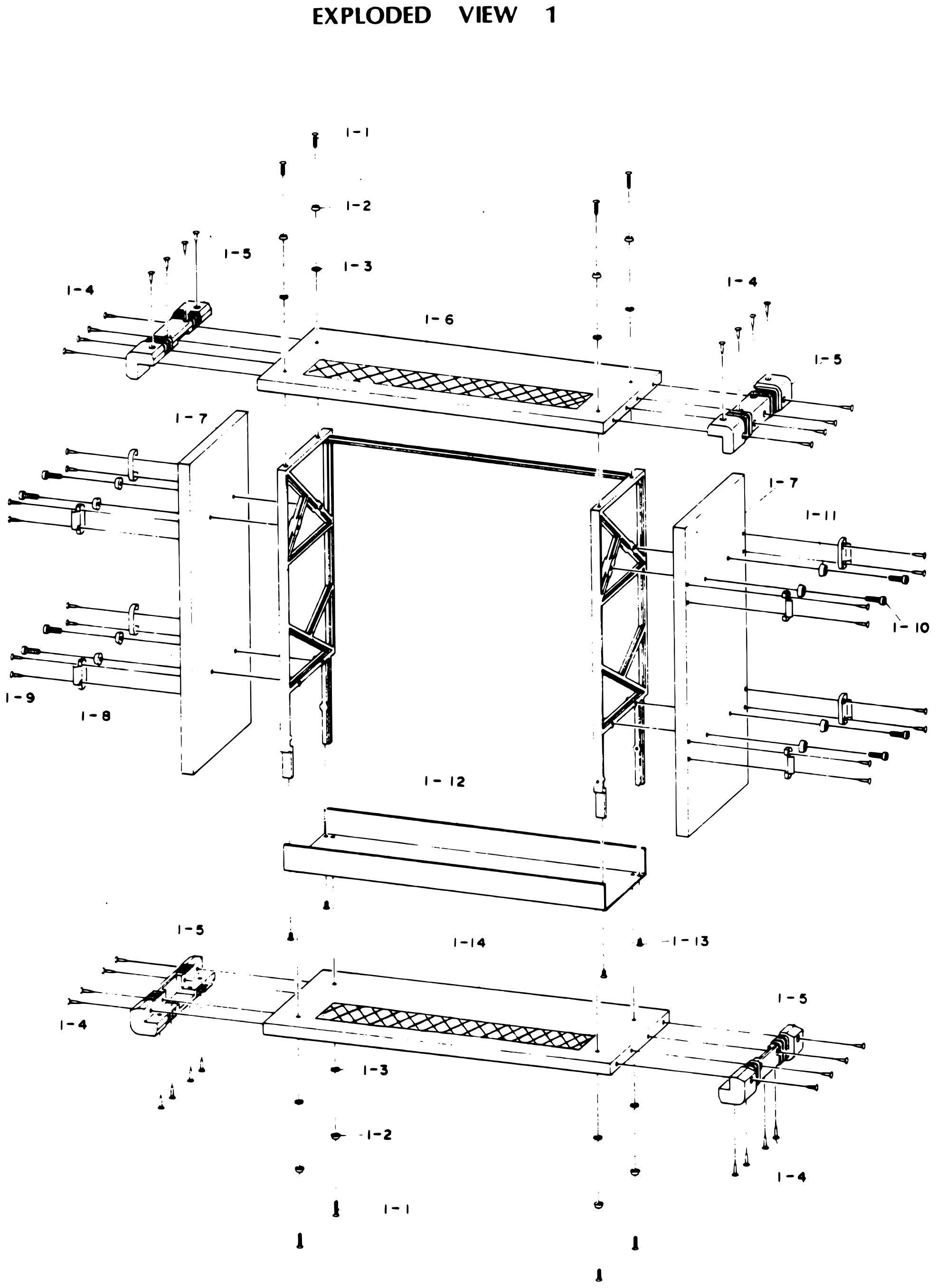 ⤢ zoomEXPLODED VIEW 1: the wooden case pulled apart around the machine frame: the top and bottom boards with their mesh panels, the two side boards with their latches and cap screws, the under cover, and the corner protectors with their wood screws, display washers and sheets · Redrawn as vector — zooms cleanly ·
PARTS LIST 2↑ TOP
| Ref. No. | Description | Parts No. | Notes |
|---|---|---|---|
| 2-1 | Screw | EZ-09-M3x20 | |
| 2-2 | Display Washer | TY-800-021 | |
| 2-3 | Sheet | TY-800-017 | |
| 2-4 | Display Panel | TD-5250D-005 | |
| 2-5 | Screw | EZ-09-M3x14 | |
| 2-6 | Display Panel | TD-5250D-003 | |
| 2-7 | Screw | EZ-09-M4x12 | |
| 2-8 | Screw | EZ-09-M4x14 | |
| 2-9 | Mounting Base | TD-5250D-001 | |
| 2-10 | W-W Resistor | RS-99-KNH40V1S-600ohm | |
| 2-11 | W-W Resistor | RS-99-KNH30V2S-200ohm | |
| 2-12 | Power Transfomer | ET-11-199(8SD,½QXD) ET-11-209(QXD,2SD₂) | |
| 2-13 | Frame | TD-5251D-001 | |
| 2-14 | Screw | EZ-09-M4x10 | |
| 2-15 | Frame Stud | TD-5010-008 | |
| 2-16 | Plain Washer | EZ-09-M4 | |
| 2-17 | Spring Washer | EZ-09-M4 | |
| 2-18 | Nut | EZ-09-M4 | |
| 2-19 | Panel Supporter | TD-5250-006 | |
| 2-20 | Screw | EZ-09-M3x8 | |
| 2-21 | Plain Washer | EZ-09-M3 | |
| 2-22 | Screw | EZ-09-3x10⁵ | |
| 2-23 | Screw | EZ-09-M3x90 | |
| 2-24 | Nut | EZ-09-M3 | |
| 2-25 | Spring Washer | EZ-09-M3 | |
| 2-26 | Cover | TD-5250D-008 | |
| 2-27 | Connector Panel | TD-5250D-007 | |
| 2-28 | Cap Screw | EZ-09-M4x6 | |
| 2-29 | Screw | EZ-09-M3x8 |
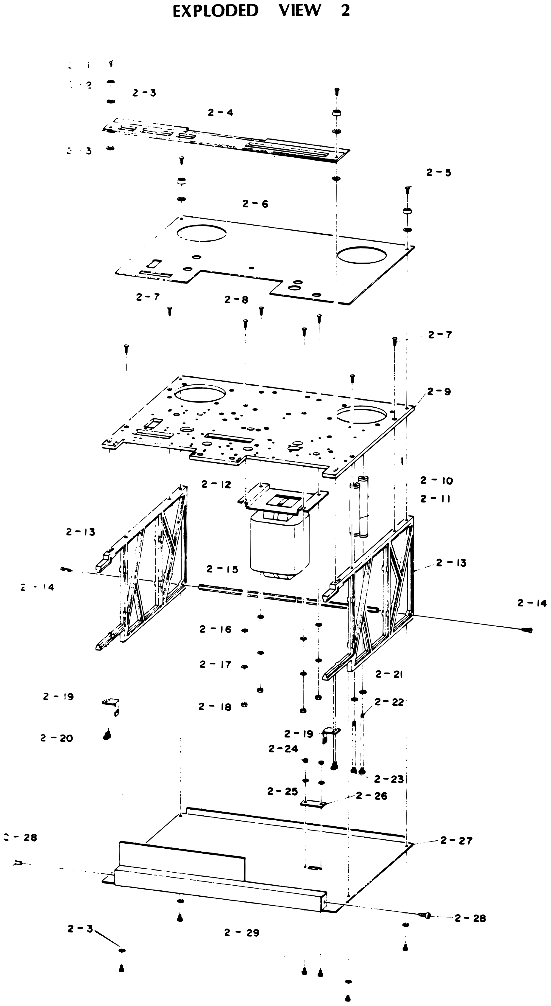 ⤢ zoomEXPLODED VIEW 2: the deck structure from the top display panels down through the mounting base, the power transformer and wire-wound resistors, the two side frames with their stud, and the connector panel and cover underneath · Redrawn as vector — zooms cleanly ·
PARTS LIST 3↑ TOP
| Ref. No. | Description | Parts No. | Notes |
|---|---|---|---|
| 3-1 | Reel Clamper | [unclear] | |
| 3-2 | Screw | EZ-09-M4x8 | |
| 3-3 | Reel Table | TW-424-001 | |
| 3-4 | Reel Shaft Holder | TW-424-002 | |
| 3-5 | Cap Screw | EZ-09-M4x10 | |
| 3-6 | Reel Protector | TW-424-009 | |
| 3-7 | Display Panel | TD-5250D-003 | |
| 3-8 | Screw | EZ-09-M4x14 | |
| 3-9 | Mounting Base | TD-5250D-001 | |
| 3-10 | Switch Supporter | PA-282-003 | |
| 3-11 | Screw | EZ-09-M3x6 | |
| 3-12 | Rotary Switch | SW-99-HZR0036-01-010 | |
| 3-13 | Screw | EZ-09-M2x6 | |
| 3-14 | Belt | TB-5070-16 | |
| 3-15 | Screw | EZ-09-M4x10 | |
| 3-16 | Reel Motor Supporter | TW-421-018 | |
| 3-17 | Spring Washer | EZ-09-M4 | |
| 3-18 | Nut | EZ-09-M4 | |
| 3-19 | Reel Motor | EM-506-019 | |
| 3-20 | Capacitor Holder L | TW-421-017L | |
| 3-21 | Capacitor Holder R | TW-421-017R | |
| 3-22 | Brake Base L | TW-421-009 | |
| 3-23 | Brake Base R | TW-421-007 | |
| 3-24 | Cap Screw | EZ-09-M3x8 | |
| 3-25 | Brake Guide | TW-421-004 | |
| 3-26 | Spring | For 8SD or ½QXD:SG-100-068 For QXD or 2SD₂:SG-100-052 | |
| 3-27 | Brake Arm | TW-424-008 | |
| 3-28 | Retaining Ring | EZ-09-ETWJ-2 | |
| 3-29 | Brake Band Assembly | TW-424-00C | |
| 3-30 | Rolled Pin | EZ-09-3dx16 | |
| 3-31 | Brake Dram | TW-424-007 | |
| 3-32 | Retaining Ring | EZ-09-ETWJ-2 | |
| 3-33 | Solenoid Pin | TY-400-015 | |
| 3-34 | Cord Clamper | EZ-09 | |
| 3-35 | Solenoid | SO-334 DC24V | |
| 3-36 | MP Capacitor | CD-99-MPL-5.5microF | |
| 3-37 | Plain Washer | EZ-09-M3 |
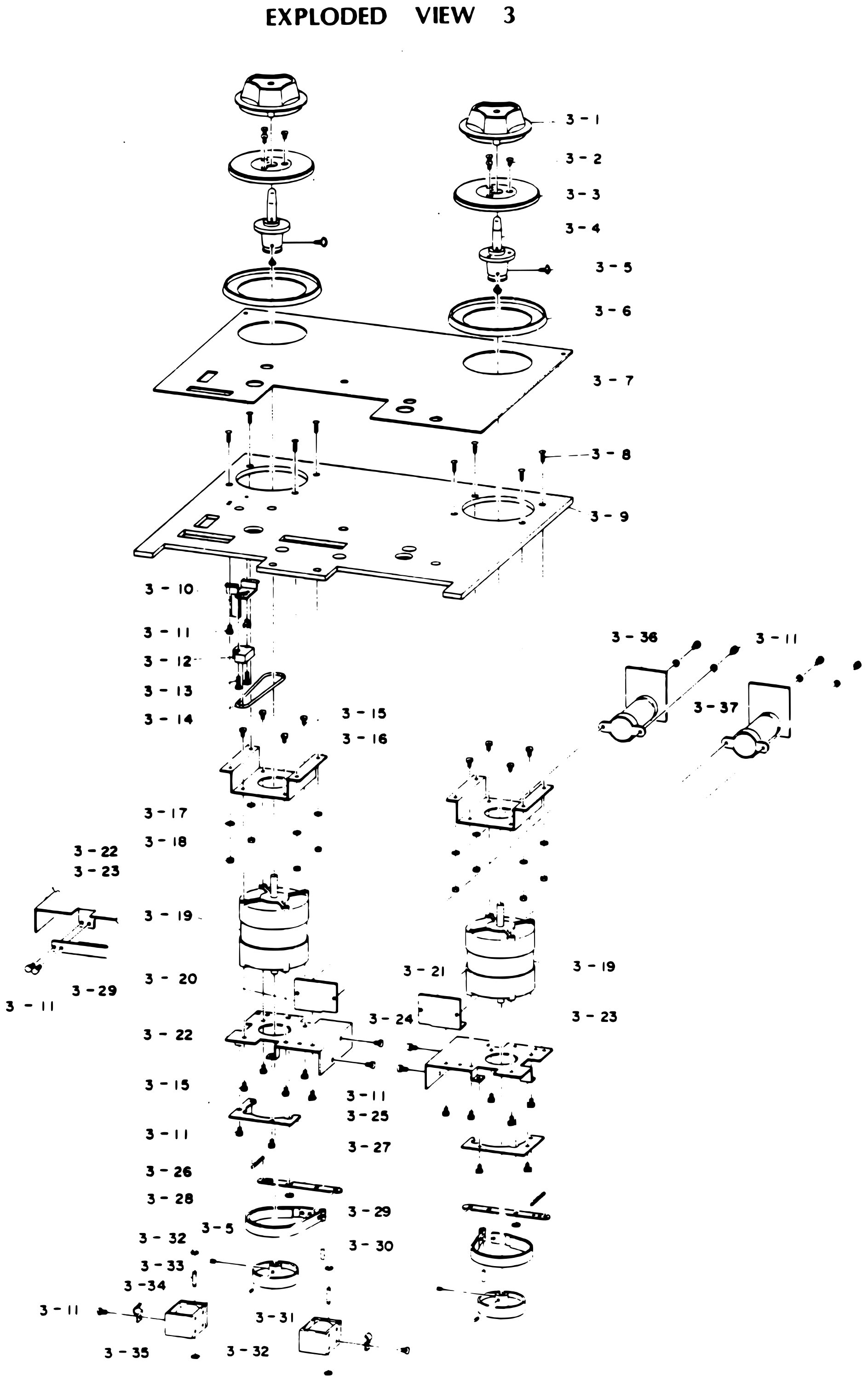 ⤢ zoomEXPLODED VIEW 3: the reel drive for both reels: reel clampers, tables and shaft holders over the display panel and mounting base, the reel motors on their supporters with the MP capacitors, and below them the brake bases, band brakes, drums and solenoids, with the rotary switch and its belt on the left · Redrawn as vector — zooms cleanly ·
PARTS LIST 4↑ TOP
| Ref. No. | Description | Parts No. | Notes |
|---|---|---|---|
| 4-1 | Knob | NB-31-037 | |
| 4-2 | Set Screw | EZ-09-M3x3 | |
| 4-3 | Dust Cap | TC-423-007 | |
| 4-4 | Display panel | TD-5250D-003 | |
| 4-5 | Screw | EZ-09-M4x10 | |
| 4-6 | Screw | EZ-09-M3x8 | |
| 4-7 | Mounting Base | TD-5250D-001 | |
| 4-8 | Stud | ST-086 | |
| 4-9 | Variable Resistor | VR-29-EVH-Y03R25B52 | |
| 4-10 | Variable Resistor Supporter | TC-427-003 | |
| 4-11 | Screw | EZ-09-M4x10 | |
| 4-12 | Motor Supporter | TC-212-001 | |
| 4-13 | Capstan Drive Motor | EM-710-007A | |
| 4-14 | Nut | EZ-09-M3 | |
| 4-15 | Spring Washer | EZ-09-M3 | |
| 4-16 | Radiator | TC-212-002 | |
| 4-17 | Screw | EZ-09-M3x8 | |
| 4-18 | Screw | EZ-09-M3x6 | |
| 4-19 | Power Supply PCB Assembly | PA-377 | |
| 4-20 | PCB Supporter | TC-427-004 | |
| 4-21 | Fuse Holder | FS-89-F-3294 | |
| 4-22 | Fuse | FS-19-2A | |
| 4-23 | Screw | EZ-09-M3x10 |
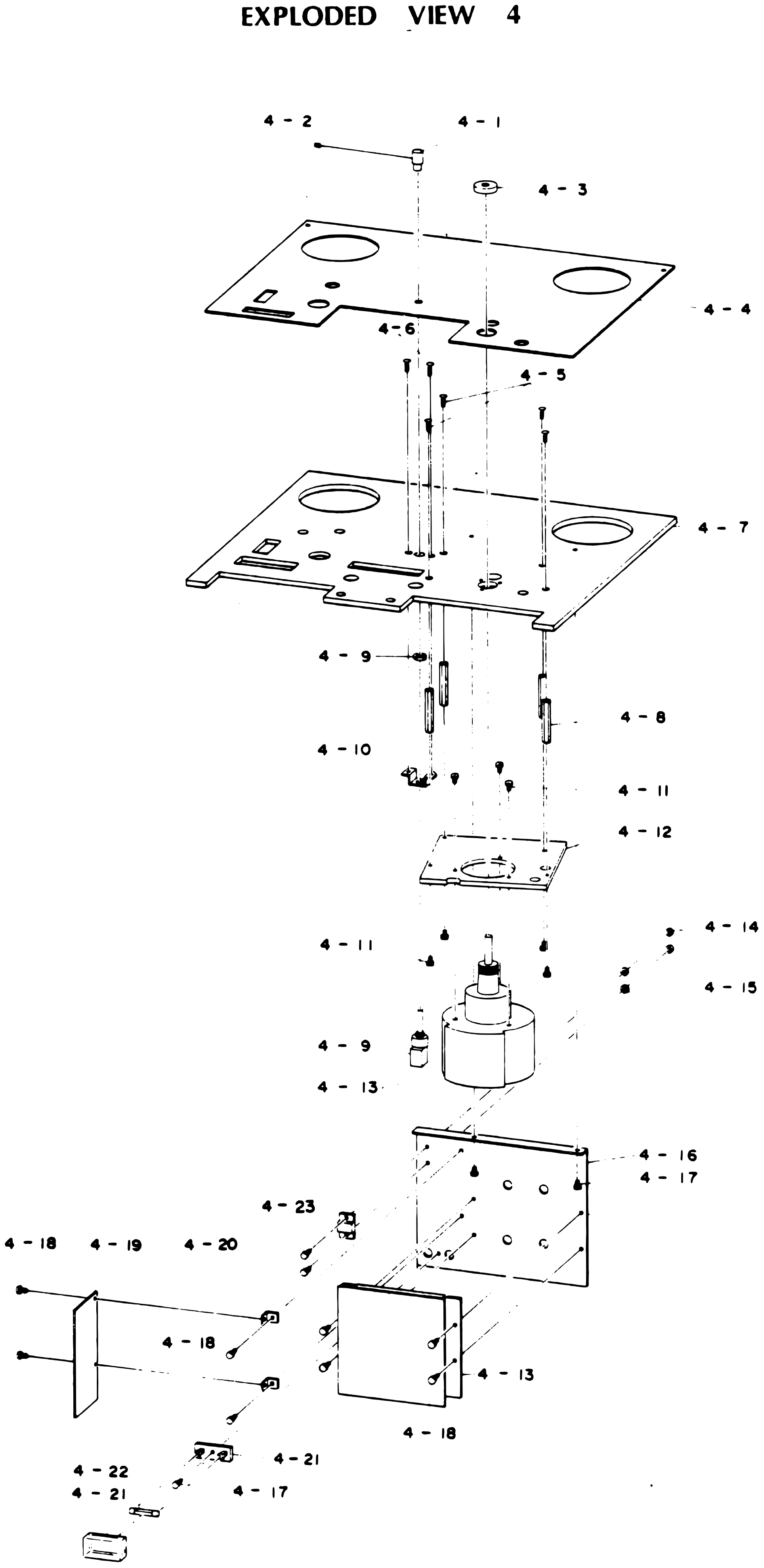 ⤢ zoomEXPLODED VIEW 4: the capstan drive: the knob and dust cap on the display panel, the mounting base, the variable resistor on its supporter, the capstan drive motor on its supporter with the radiator, and the power supply board with its fuse holder and fuse · Redrawn as vector — zooms cleanly ·
PARTS LIST 5 For Model 8SD or ½QXD and Difference of Model 2SD₂ or QXD↑ TOP
| Ref. No. | Description | Parts No. | Notes |
|---|---|---|---|
| 5-1 | Screw | EZ-09-M3x8 | |
| 5-2 | Pinch Roller Cap | TP-419-002A | |
| 5-3 | Retaining Ring | EZ-09-RTW-19 | |
| 5-4 | Bearing | BG-19-626ZZ | |
| 5-5 | Coller | TP-408-02 | |
| 5-6 | Pinch Roller | TP-210-001 | |
| 5-7 | Pinch Roller Shaft | TP-210-002 | |
| 5-8 | Display Panel | TD-5250D-003 | |
| 5-9 | Screw | EZ-09-M3x10 | |
| 5-10 | Screw | EZ-09-M4x12 | |
| 5-11 | Mounting Base | TD-5250D-001 | |
| 5-12 | Spring Supportor | TY-900-019 | |
| 5-13 | Screw | EZ-09-M3x6 | |
| 5-14 | Spring | SG-100-048 | |
| 5-15 | Pinch Roller Arm | TP-420-002 | |
| 5-16 | Cap Screw | EZ-09-M4x10 | |
| 5-17 | Arm Shaft | TP-420-001 | |
| 5-18 | Retaining Ring | EZ-09-ETWJ-4 | |
| 5-19 | Double Nut | EZ-09-M4 | |
| 5-20 | Spring | SG-500-031 | |
| 5-21 | Spherical Washer | TP-401-007 | |
| 5-22 | Fiber Washer | EZ-09-M4 | |
| 5-23 | Retaining Ring | EZ-09-ETWJ-3 | |
| 5-24 | Adjusting Screw | TP-416-009 | |
| 5-25 | Retaining Ring | EZ-09-ETWJ-2 | |
| 5-26 | Solenoid Pin | TY-400-015 | |
| 5-27 | Solenoid | SO-317 DC24V | |
| 5-28 | Stopper | TY-200-013 | |
| 5-29 | Plain Washer | EZ-09-M3 | |
| 5-30 | Screw | EZ-09-M3x6 |
For Model QXD or 2SD₂ (Difference)↑ TOP
| Ref. No. | Description | Parts No. | Notes |
|---|---|---|---|
| 5-31 | Pinch Roller Cap | TP-416-001 | |
| 5-32 | Set Screw | EZ-09-M3x8 | |
| 5-33 | Thrust Washer | EZ-09-Ø6x0.25t | |
| 5-34 | Pinch Roller | TP-416-010 | |
| 5-35 | Retaining Ring | EZ-09-ETWJ-4 | |
| 5-36 | Pinch Roller Shaft | TP-416-002 |
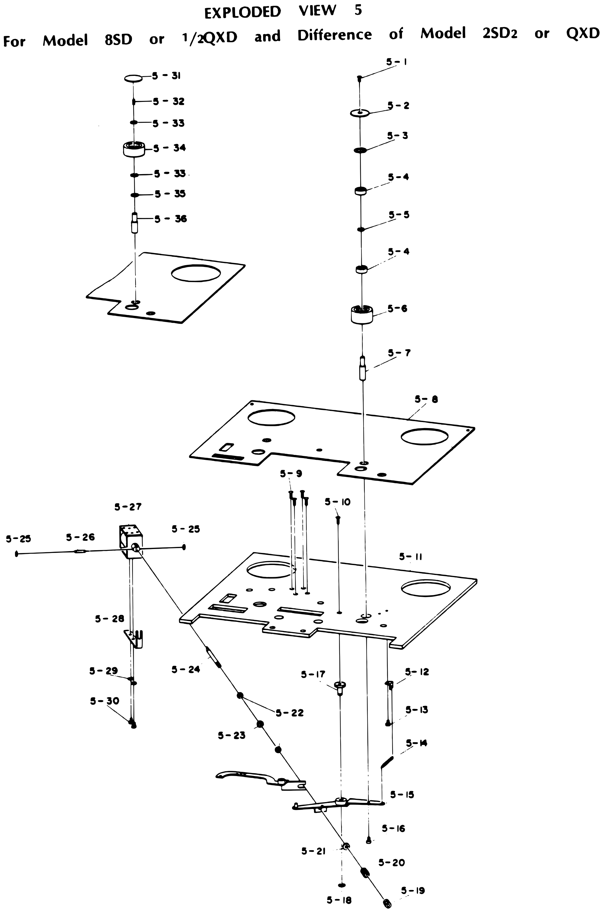 ⤢ zoomEXPLODED VIEW 5 For Model 8SD or ½QXD and Difference of Model 2SD₂ or QXD: the pinch roller assembly stacked on its shaft above the display panel and mounting base, the pinch roller arm with its spring, adjusting screw and solenoid linkage below, and, at upper left, the differing pinch roller stack for the QXD and 2SD₂ · Redrawn as vector — zooms cleanly ·
PARTS LIST 6-1 For Model 8SD↑ TOP
| Ref. No. | Discription | Parts No. | Notes |
|---|---|---|---|
| 6-1 | Head Housing Assembly | TH-446-00B | |
| 6-2 | Screw | EZ-09-M3x8 | |
| 6-3 | Screw | EZ-09-M2.6x6 | |
| 6-4 | Connector | CN-09-MR-34M | |
| 6-5 | Connector | CN-09-MR-16M | |
| 6-6 | Screw | EZ-09-M3x8 | |
| 6-7 | Connector Supporter | TH-212-006 | |
| 6-8 | Screw | EZ-09-M4x6 | |
| 6-9 | Screw | EZ-09-M3x6 | |
| 6-10 | Connector | CN-09-MR-16F | |
| 6-11 | Connector | CN-09-MR-34F | |
| 6-12 | Erase Head Assembly | TH-212-00D | |
| 6-13 | Record Head Assembly | TH-212-00E | |
| 6-14 | Playback Head Assembly | TH-212-00F | |
| 6-15 | Tape Guide | TH-212-005 | |
| 6-16 | Screw | EZ-09-M3x15 | |
| 6-17 | Head Base | TH-212-002 | |
| 6-18 | Screw | EZ-09-M3x8 | |
| 6-19 | Display Panel | TD-5250D-003 | |
| 6-20 | Mounting Base | TD-5250D-001 | |
| 6-21 | Cord Clamper | EZ-01-001 | |
| 6-22 | Screw | EZ-09-M3x6 | |
| 6-23 | Cord Clamper | TY-200-006 | |
| 6-24 | Spring Washer | EZ-09-M3 | |
| 6-25 | Nut | EZ-09-M3 | |
| 6-26 | Erase Head | SH-5308-21-001 | |
| 6-27 | Head Supporter B | TH-212-004 | |
| 6-28 | Screw | EZ-09-M2x5 | |
| 6-29 | Shield Can | TH-212-001 | |
| 6-30-1 | Record Head | SH-6308-21-001 | |
| 6-30-2 | Reproduce Head | SH-7308-21-001 | |
| 6-31 | Head Supporter A | TH-212-003 |
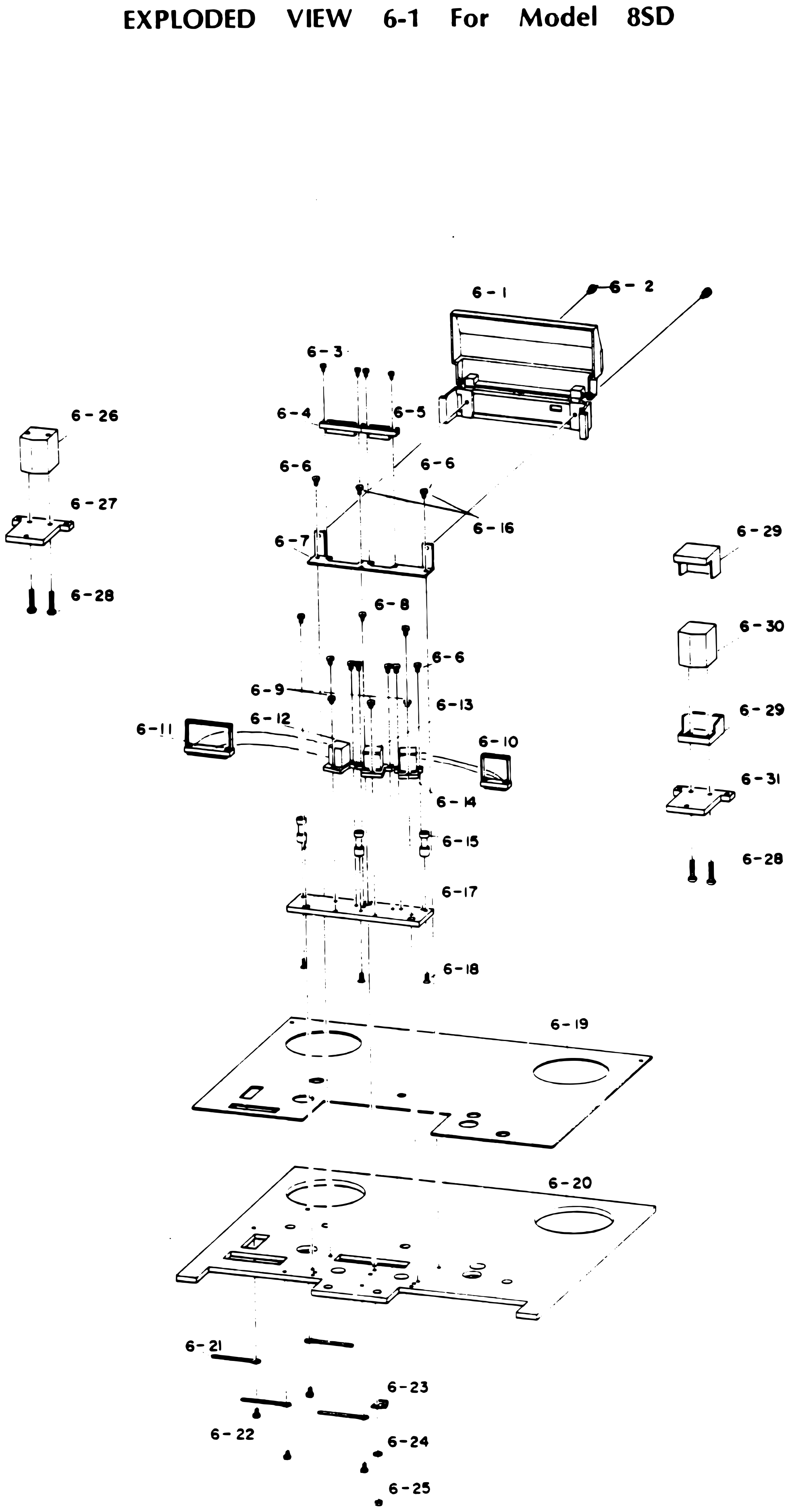 ⤢ zoomEXPLODED VIEW 6-1 For Model 8SD: the head assembly: the head housing cover and its screws, the connectors on the connector supporter, the erase, record and playback head assemblies with their tape guides on the head base, the display panel and mounting base below with the cord clampers underneath, and, at the sides, the erase head on head supporter B and the record or reproduce head in its shield can on head supporter A · Redrawn as vector — zooms cleanly ·
PARTS LIST 6-2 For Model ½QXD↑ TOP
| Ref. No. | Description | Parts No. | Notes |
|---|---|---|---|
| 6-1 | Head Housing Assy | TH-446-00B | |
| 6-2 | Screw | EZ-09-M3x8 | |
| 6-3 | Screw | EZ-09-M3x10 | |
| 6-4 | Connector | CN-09-1150-028-009 | |
| 6-5 | Screw | EZ-09-M3x6 | |
| 6-6 | Connector Supporter | TH-213-008 | |
| 6-7 | Screw | EZ-09-M4x6 | |
| 6-8 | Screw | EZ-09-M3x8 | |
| 6-9 | Screw | EZ-09-M3x6 | |
| 6-10 | Erase Head Assy | TH-213-005 | |
| 6-11 | Record Head Assy | TH-213-006 | |
| 6-12 | Reproduce Head Assy | TH-213-007 | |
| 6-13 | Tape Guide | TH-212-005 | |
| 6-14 | Head Base | TH-213-001 | |
| 6-15 | Screw | EZ-09-M3x8 | |
| 6-16 | Display Panel | TD-5250D-003 | |
| 6-17 | Mounting Base | TD-5250D-001 | |
| 6-18 | Head P.C.B. Assy | PA-386 | |
| 6-19 | Erase Head | SH-1304-21-001 | |
| 6-20 | Head Supporter B | TH-213-003 | |
| 6-21 | Screw | EZ-09-M2x5 | |
| 6-22 | Shield Can | TH-213-004 | |
| 6-23 | Record Head | SH-2304-21-001 | |
| 6-24 | Reproduce Head | SH-3304-21-001 | |
| 6-25 | Head supporter A | TH-213-002 |
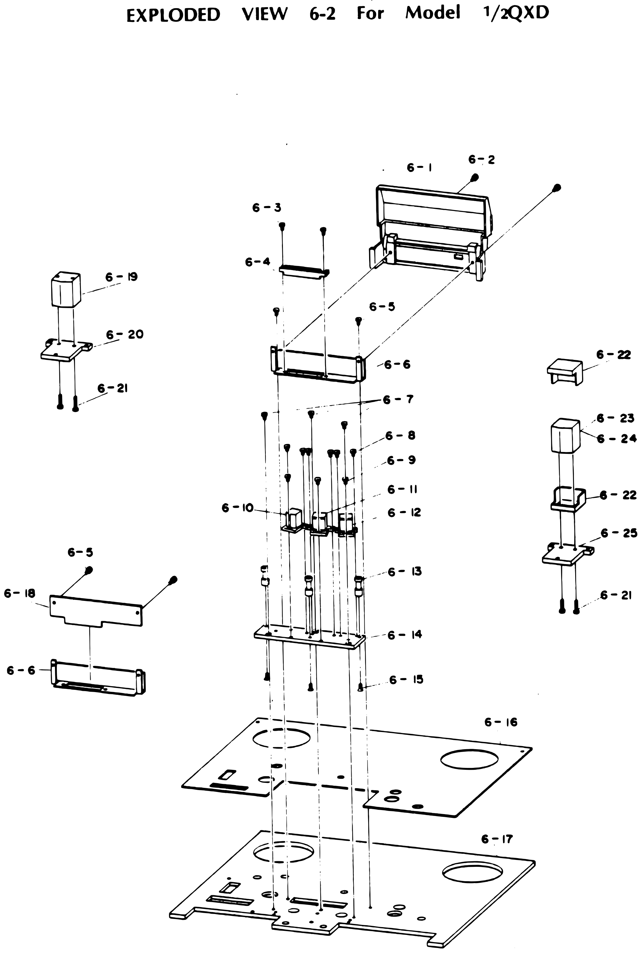 ⤢ zoomEXPLODED VIEW 6-2 For Model ½QXD: the head assembly: the head housing cover, the connector on its supporter, the erase, record and reproduce head assemblies with their tape guides on the head base above the display panel and mounting base, and, at the sides, the head P.C.B. on the connector supporter, the erase head on head supporter B, and the record and reproduce heads in their shield can on head supporter A · Redrawn as vector — zooms cleanly ·
PARTS LIST 6-3 For Model QXD↑ TOP
| Ref. No. | Description | Parts No. | Notes |
|---|---|---|---|
| 6-1 | Screw | EZ-09-M3x6 | |
| 6-2 | Screw | EZ-09-M3x8 | |
| 6-3 | Plain Washer | EZ-09-M3 | |
| 6-4 | Head P.C.B. Assy | PA-386 | |
| 6-5 | Screw | EZ-09-M3x4 | |
| 6-6 | Plain Washer | EZ-09-M3 | |
| 6-7 | Protector Sheet | TH-438-009 | |
| 6-8 | Head Base | TH-446-001 | |
| 6-9 | Head Housing Assy | TH-446-00B | |
| 6-10 | Tape Guide | TH-438-004 | |
| 6-11 | Screw | EZ-09-M3x6 | |
| 6-12 | Screw | EZ-09-M3x10 | |
| 6-13 | Connector | CN-09-1150-028-009 | |
| 6-14 | Housing Base | TH-455-001 | |
| 6-15 | Display Panel | TD-5250D-003 | |
| 6-16 | Mounting Base | TD-5250D-001 | |
| 6-17 | Screw | EZ-09-M3x15 | |
| 6-18 | Cord Clamper | EZ-01-001 | |
| 6-19 | Screw | EZ-09-M3x10 | |
| 6-20 | Screw | EZ-09-M3x12 | |
| 6-21 | Head Adjusting Spring | SG-500-040 | |
| 6-22 | Head Adjusting Spring | SG-500-063 | |
| 6-23 | Screw | EZ-09-M2x5 | |
| 6-24 | Spring Washer | EZ-09-M2 | |
| 6-25 | Screw | EZ-09-M2x4 | |
| 6-26 | Plain Washer | EZ-09-M2 | |
| 6-27 | Head Supporter C | TH-450-001 | |
| 6-28 | Head Supporter B | TH-442-002 | |
| 6-29 | Head Supporter D | TH-450-003 | |
| 6-30 | Spacer | TH-450-005 | |
| 6-31 | Shield Can | TH-450-004 | |
| 6-32 | Reproduce Head | SH-7204-11-004 | |
| 6-33 | Record Head | SH-6204-11-004 | |
| 6-34 | Erase Head | SH-5204-11-001 |
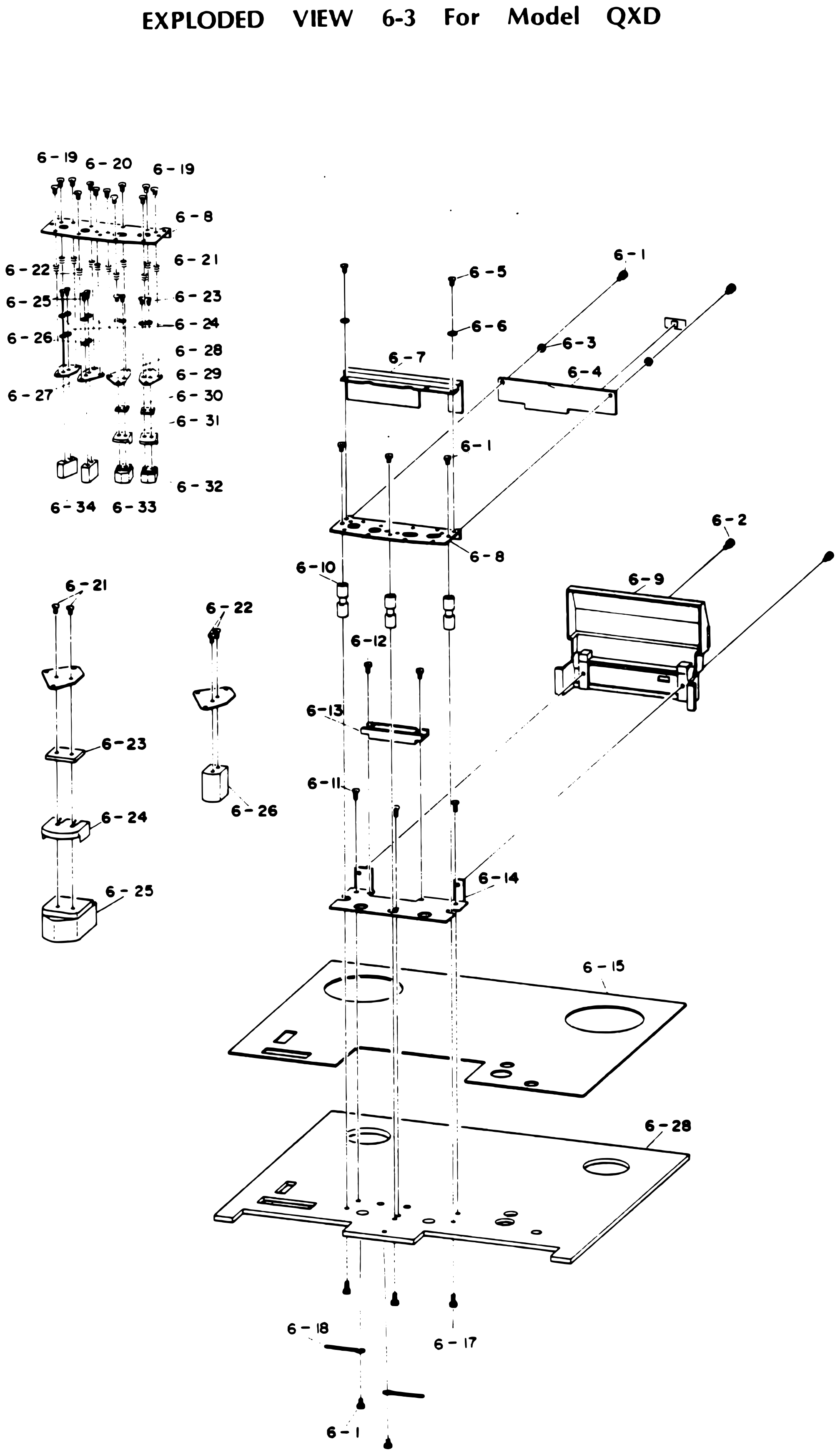 ⤢ zoomEXPLODED VIEW 6-3 For Model QXD: the head assembly: the protector sheet and head P.C.B. over the head base, the tape guides, the connector, the head housing cover, and the housing base above the display panel and mounting base; at upper left the head stack of adjusting springs, head supporters, spacers and shield cans over the reproduce, record and erase heads, with enlarged details of two head mountings below it · Redrawn as vector — zooms cleanly ·
PARTS LIST 6-4 For Model 2SD₂↑ TOP
| Ref. No. | Description | Parts No. | Notes |
|---|---|---|---|
| 6-1 | Screw | EZ-09-M3x6 | |
| 6-2 | Blind | TY-900-029 | |
| 6-3 | Plain Washer | EZ-09-M3 | |
| 6-4 | Head P.C.B. Assy | PA-387 | |
| 6-5 | Screw | EZ-09-M3x4 | |
| 6-6 | Screw | EZ-09-M3x8 | |
| 6-7 | Protector Sheet | TH-438-009 | |
| 6-8 | Head Base | TH-446-001 | |
| 6-9 | Head Housing Assy | TH-446-00B | |
| 6-10 | Tape Guide | TH-438-004 | |
| 6-11 | Screw | EZ-09-M3x6 | |
| 6-12 | Screw | EZ-09-M3x10 | |
| 6-13 | Connector | CN-09-1150-028-009 | |
| 6-14 | Housing Base | TH-455-001 | |
| 6-15 | Display Panel | TD-5250D-003 | |
| 6-16 | Mounting Base | TD-5250D-001 | |
| 6-17 | Cord Clamper | EZ-01-001 | |
| 6-18 | Screw | EZ-09-M3x15 | |
| 6-19 | Screw | EZ-09-M3x10 | |
| 6-20 | Screw | EZ-09-M3x12 | |
| 6-21 | Head Adjusting Spring | SG-500-040 | |
| 6-22 | Head Adjusting Spring | SG-500-063 | |
| 6-23 | Screw | EZ-09-M2x5 | |
| 6-24 | Screw | EZ-09-M2x4 | |
| 6-25 | Spring Washer | EZ-09-M2 | |
| 6-26 | Plain Washer | EZ-09-M2 | |
| 6-27 | Head Supporter D | TH-450-003 | |
| 6-28 | Head Supporter B | TH-422-002 | |
| 6-29 | Head Supporter A | TH-422-001 | |
| 6-30 | Spacer | TH-450-005 | |
| 6-31 | Shield Can | TH-450-004 | |
| 6-32 | Reproduce Head | SH-7202-11-001 | |
| 6-33 | Record Head | SH-6202-11-001 | |
| 6-34 | Reproduce Head | SH-7204-11-001 | |
| 6-35 | Erase Head | SH-5202-11-001 |
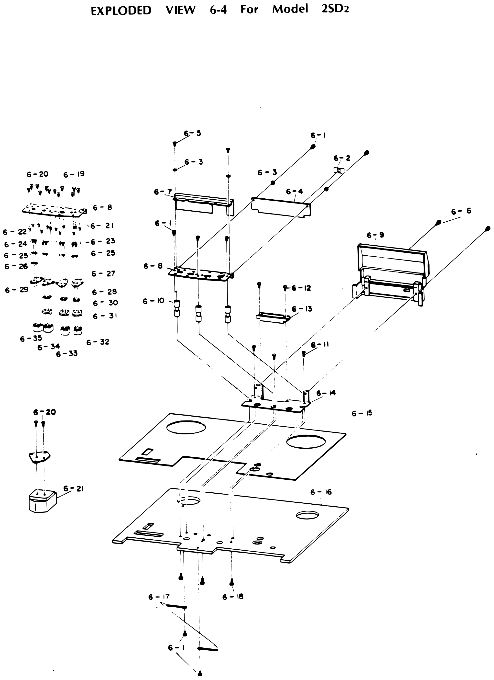 ⤢ zoomEXPLODED VIEW 6-4 For Model 2SD₂: the head assembly: the blind, protector sheet and head P.C.B. over the head base, the tape guides, the connector, the head housing cover, and the housing base above the display panel and mounting base; at upper left the head stack of adjusting springs, washers, head supporters, spacers and shield cans over the four heads, with an enlarged detail of one head mounting below it · Redrawn as vector — zooms cleanly ·
PARTS LIST 7↑ TOP
| Ref. No. | Discription | Parts No. | Notes |
|---|---|---|---|
| 7-1 | Cue Lever | TR-416-001 | |
| 7-2 | Display Panel | TD-5250D-003 | |
| 7-3 | Screw | EZ-09-M4x12 | |
| 7-4 | Screw | EZ-09-M3x10 | |
| 7-5 | Mounting Base | TD-5250D-001 | |
| 7-6 | Arm Shaft | TP-420-001 | |
| 7-7 | Arm Shaft | TR-413-002 | |
| 7-8 | Shifter Arm A | TR-413-003 | |
| 7-9 | Shifter Arm B | TR-413-007 | |
| 7-10 | Retaining Ring | EZ-09-ETWJ-3 | |
| 7-11 | Spring | SG-100-050 | |
| 7-12 | Arm Shaft | TR-414-003 | |
| 7-13 | Pinch Roller Arm | TP-420-002 | |
| 7-14 | Retaining Ring | EZ-09-ETW-4 | |
| 7-15 | Fook | TR-419-003 | |
| 7-16 | Screw | EZ-09-M3x6 | |
| 7-17 | Blind | TY-900-053 | |
| 7-18 | Cue Arm Stopper | TY-200-071 | |
| 7-19 | Cue Lock Arm | TR-419-004 | |
| 7-20 | Plain Washer | EZ-09-M3 | |
| 7-21 | Cap Screw | EZ-09-M3x8 | |
| 7-22 | Cue Arm | TR-419-001 |
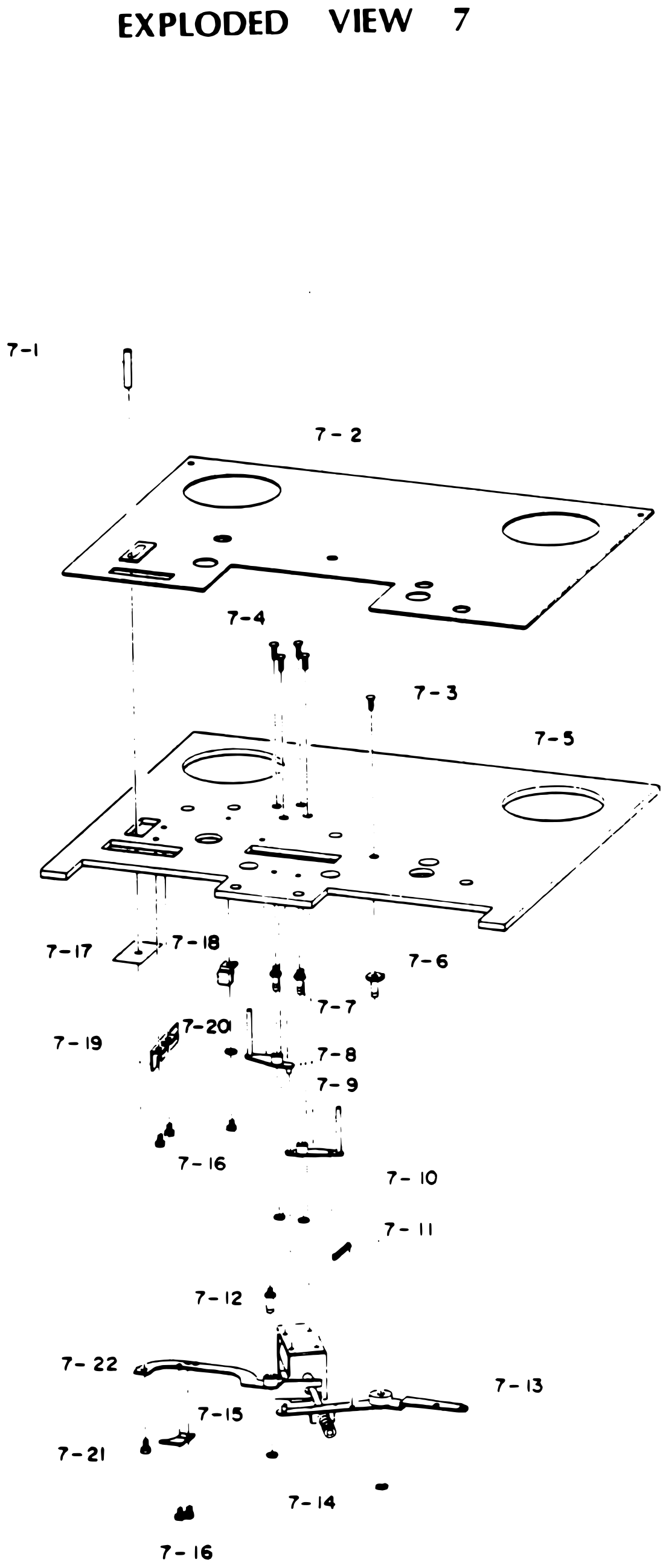 ⤢ zoomEXPLODED VIEW 7: the cue mechanism: the cue lever passing down through the display panel and mounting base, the arm shafts and shifter arms with their spring and retaining rings under the base, the cue arm stopper, cue lock arm and blind at left, and the cue arm and pinch roller arm at the bottom · Redrawn as vector — zooms cleanly ·
PARTS LIST 8 For Model 8SD or ½QXD and Difference of Model 2SD₂ or QXD↑ TOP
| Ref. No. | Description | Parts No. | Notes |
|---|---|---|---|
| 8-1 | Guide Roller | TG-213-001 | |
| 8-2 | Bearing | BG-19-606ZZ | |
| 8-3 | Roller Holder | TG-425-002 | |
| 8-4 | Screw | EZ-09-M3x35 | |
| 8-5 | Guide Pole | TD-5450-007 | |
| 8-6 | Display Panel | TD-5250D-003 | |
| 8-7 | Mounting Base | TD-5250D-001 | |
| 8-8 | Holder Nut | TG-425-004 | |
| 8-9 | Set Screw | EZ-09-M3x4 | |
| 8-10 | Roller Pulley | TG-425-003 | |
| 8-11 | Belt | TB-5045-12 | |
| 8-12 | Counter | CT-19-MP-499-01SPEC | |
| 8-13 | Counter Supporter | TZ-126-001 | |
| 8-14 | Screw | EZ-09-M3x6 |
For Model 2SD₂ or QXD (Difference)↑ TOP
| Ref. No. | Description | Parts No. | Notes |
|---|---|---|---|
| 8-15 | Roller Cap | TG-424-01 | |
| 8-16 | Thrust Washer | EZ-09-Ø8x0.25t | |
| 8-17 | Roller Shaft | TG-424-02 | |
| 8-18 | Sleeve | TG-424-03 | |
| 8-19 | Roller | TG-424-04 | |
| 8-20 | Roller Base | TG-424-05 |
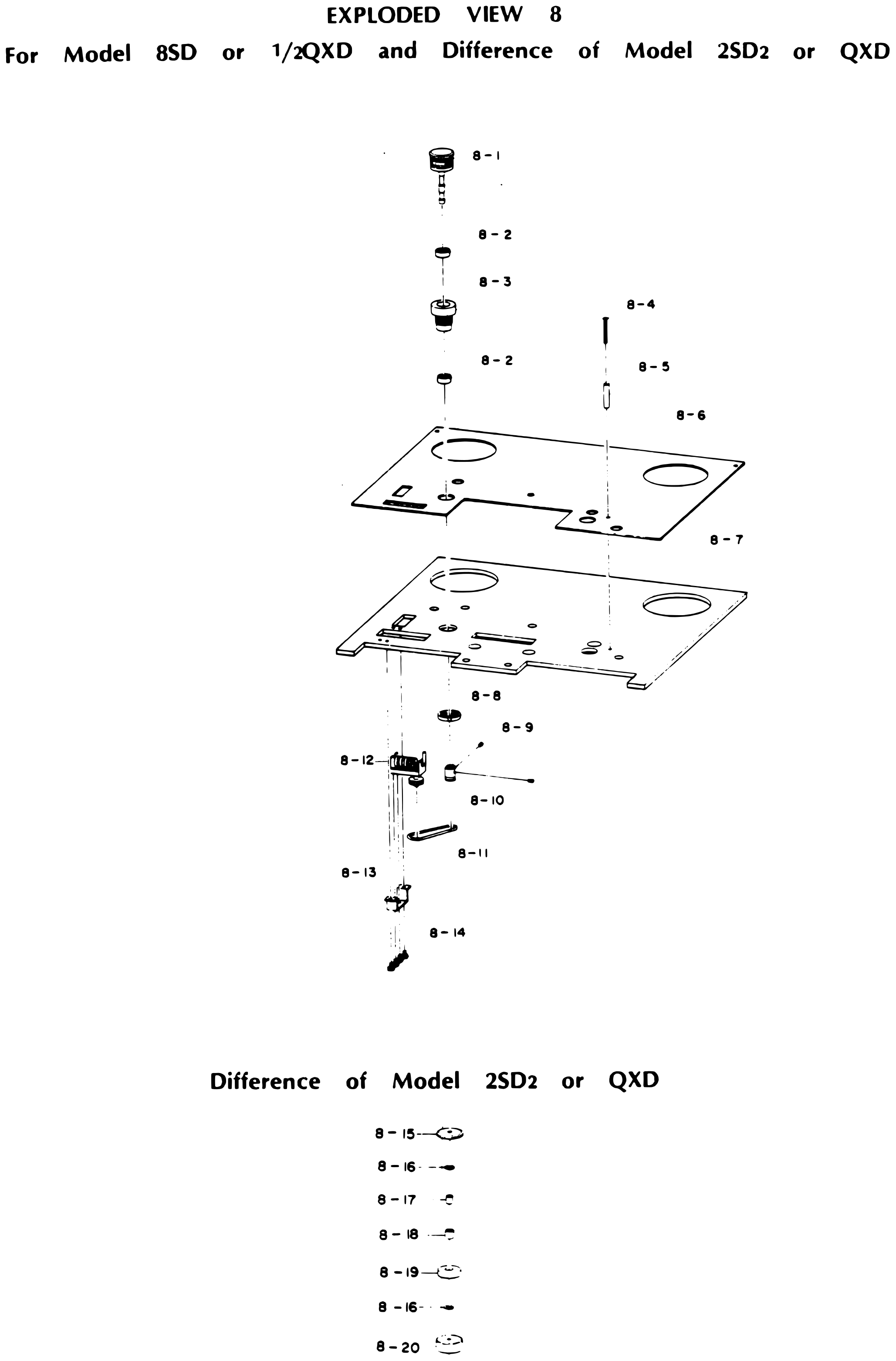 ⤢ zoomEXPLODED VIEW 8 For Model 8SD or ½QXD and Difference of Model 2SD₂ or QXD: the guide roller on its bearings and roller holder above the display panel and mounting base, the guide pole and its screw at right, the holder nut, roller pulley and belt below driving the counter on its supporter, and, at the bottom, the differing guide roller parts for the 2SD₂ and QXD stacked in order · Redrawn as vector — zooms cleanly ·
PARTS LIST 9↑ TOP
| Ref. No. | Description | Parts No. | Notes |
|---|---|---|---|
| 9-1 | Display Screw | TA-420-005 | |
| 9-2 | Screw | EZ-09-M2x4 | |
| 9-3 | Tape Guide | For 8SD or ½QXD:TA-211-001 For QXD or 2SD₂:TA-420-004 | |
| 9-4 | Tention Arm | TA-420-003 | |
| 9-5 | Screw | EZ-09-M3x5 | |
| 9-6 | Arm Shaft | TA-429-001 | |
| 9-7 | Slide Washer | EZ-09-5dx0.5t | |
| 9-8 | Arm Holder | TA-420-002 | |
| 9-9 | Display Panel | TD-5250D-003 | |
| 9-10 | Mounting Base | TD-5250D-001 | |
| 9-11 | Micro Switch | SW-59-LV-3H-1A | |
| 9-12 | Screw | EZ-09-M3x25 | |
| 9-13 | Magnetic Supporter | TY-900-023 | |
| 9-14 | Screw | EZ-09-M3x6 | |
| 9-15 | Stopper | TD-5451-006 | |
| 9-16 | Spring Supporter | TY-900-020 | |
| 9-17 | Nut | TA-420-007 | |
| 9-18 | Spring Holder | TA-427-001 | |
| 9-19 | Set Screw | EZ-09-M3x6 | |
| 9-20 | Plain Washer | EZ-09-M3 | |
| 9-21 | Spring | SG-100-047B | |
| 9-22 | Switch Actuator | TA-423-002 | |
| 9-23 | Screw | EZ-09-M3x4 | |
| 9-24 | Screw | EZ-09-M3x6 | |
| 9-25 | Spring Holder | TA-429-002 | |
| 9-26 | Spring | For 8SD or ½QXD:SG-100-069 For QXD or 2SD₂:SG-100-046 | |
| 9-27 | Stopper Arm | TA-420-010 |
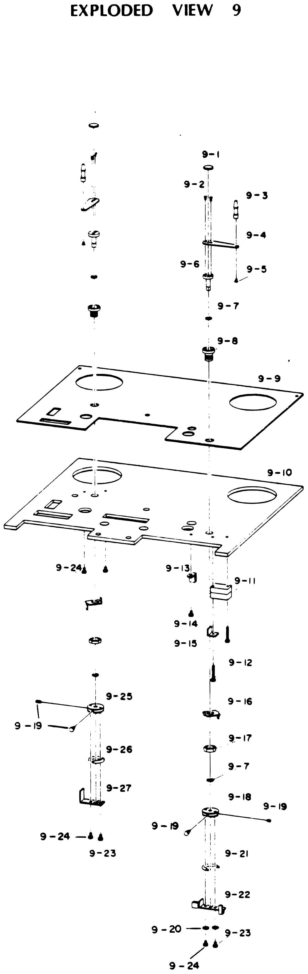 ⤢ zoomEXPLODED VIEW 9: the two tension arm assemblies, each drawn from its tape guide and tension arm on the arm shaft down through the display panel and mounting base, with the micro switch, magnetic supporter and stopper under the base on the right, and the spring holders, springs, switch actuator and stopper arm at the bottom · Redrawn as vector — zooms cleanly ·
PARTS LIST 10↑ TOP
| Ref. No. | Description | Parts No. | Notes |
|---|---|---|---|
| 10-1 | Push Button A | CR-824-001A | |
| 10-2 | Push Button C | CR-824-001C | |
| 10-3 | Push Button B | CR-824-001B | |
| 10-4 | Push Button E | CR-824-001E | |
| 10-5 | Push Button C | CR-823-001C | |
| 10-6 | Push Button B | CR-823-001B | |
| 10-7 | Push Button | CR-823-002D | |
| 10-8 | Push Button | CR-823-001A | |
| 10-9 | Push Button | CR-823-001A | |
| 10-10 | Display Panel | TD-5250D-005 | |
| 10-11 | Display Panel | TD-5250D-003 | |
| 10-12 | Mounting Base | TD-5250D-001 | |
| 10-13 | Lamp Supporter | TY-900-025 | |
| 10-14 | Screw | EZ-09-M3x6 | |
| 10-15 | Lamp Assembly | PL-19-005 | |
| 10-16 | Screw | EZ-09-M2.6x5 | |
| 10-17 | Guide | CR-823-010 | |
| 10-18 | Switch Base | CR-823-008 | |
| 10-19 | Screw | EZ-09-M3x10 | |
| 10-20 | Micro Switch | SW-59-V-1A | |
| 10-21 | Guide | CR-824-006 | |
| 10-22 | Screw | EZ-09-M3x6 | |
| 10-23 | Switch Base | CR-824-005 | |
| 10-24 | Power Switch PCB Assembly | PA-378 | |
| 10-25 | Switch Supporter L | CR-824-007L | |
| 10-26 | Switch Supporter R | CR-824-007R | |
| 10-27 | Micro Switch | SW-59-SS5GL | |
| 10-28 | Screw | EZ-09-M2x10 | |
| 10-29 | Switch Supporter | CR-824-008 | |
| 10-30 | Screw | EZ-09-M2.6x5 | |
| 10-31 | Screw | EZ-09-M2x12 |
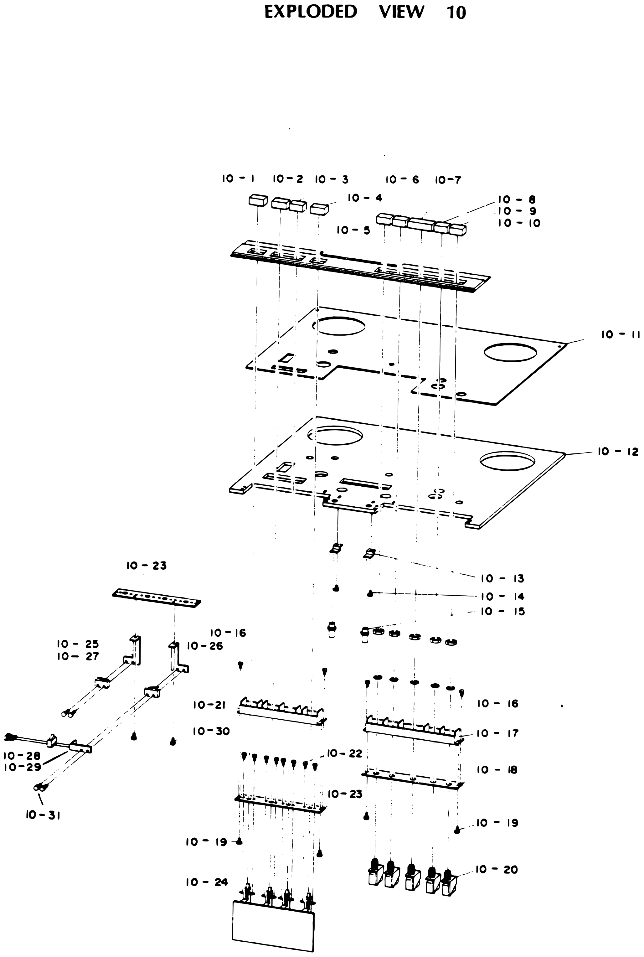 ⤢ zoomEXPLODED VIEW 10: the push buttons along the top over the narrow button panel, the display panel and the mounting base, the lamp supporters and lamp assemblies below, the two rows of micro switches on their guides and switch bases, the power switch P.C.B. assembly at the bottom, and, at left, the switch supporters with their micro switches · Redrawn as vector — zooms cleanly ·
PARTS LIST 11-1 For Model 8SD↑ TOP
| Ref. No. | Description | Parts No. | Notes |
|---|---|---|---|
| 11-1 | Screw | EZ-09-M2x6 | |
| 11-2 | Caution Label | NP-300-004 | |
| 11-3 | Screw | EZ-09-M3x8 | |
| 11-4 | Connector | CN-09-SRC02A16-10S | |
| 11-5 | Screw | EZ-09-M3x8 | |
| 11-6 | Connector | CN-09-16-R4M | |
| 11-7 | Screw | EZ-09-M3x6 | |
| 11-8 | Fuse Hollder | FS-89-S-N2052 | |
| 11-9 | Fuse | FS-19-2A | |
| 11-10 | Earth Terminal | LP-09-T-10 | |
| 11-11 | Transistor | SC-09-2SD-325E | |
| 11-12 | Power Supply IC | IC-09-7805UC | |
| 11-13 | Screw | EZ-09-M3x12 | |
| 11-14 | Spring Washer | EZ-09-M3 | |
| 11-15 | Sub-Power Supply PCB Assembly | PA-307 | |
| 11-16 | Nut | EZ-09-M3 | |
| 11-17 | Connector Panel | TD-5250D-007 | |
| 11-18 | IC | IC-09-SI-3250E | |
| 11-19 | Mother Board Assembly | PA-314 | |
| 11-20 | Master OSC Power Supply Assembly | PA-315 | |
| 11-21 | Control PCB Assembly | PA-316 | |
| 11-22 | Screw | EZ-09-M3x6 | |
| 11-23 | Control PCB Assembly | ||
| 11-24 | PCB Stopper | PA-314-001 | |
| 11-25 | Cord Stopper | RB-19-BU-3270 | |
| 11-26 | Power Cord | TY-556 | |
| 11-27 | Stopper Spacer | TD-5250-005 | |
| 11-28 | Plain Washer | EZ-09-M3 |
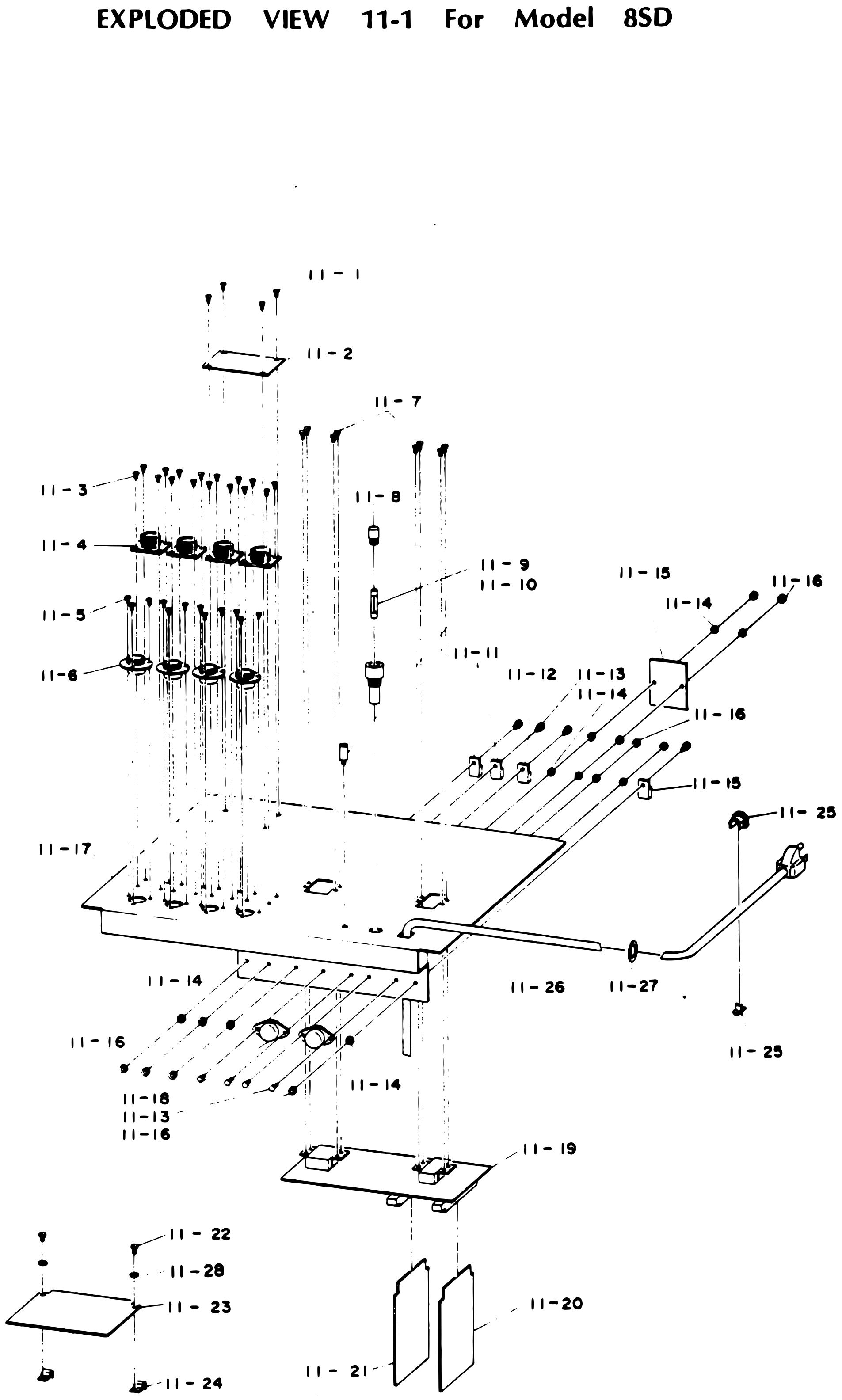 ⤢ zoomEXPLODED VIEW 11-1 For Model 8SD: the connector panel with two rows of four connectors screwed on from above, the fuse holder and fuse, the earth terminal, transistors and power supply IC on their screws and washers, the sub-power supply P.C.B. assembly at right, the power cord with its cord stoppers and spacer, the mother board below with the master oscillator power supply and control P.C.B.s plugged into it, and, at lower left, the control P.C.B. on its screws and stoppers · Redrawn as vector — zooms cleanly ·
PARTS LIST 11-2 For Model 2SD₂ and Difference of Model QXD or ½QXD↑ TOP
| Ref. No. | Description | Parts No. | Notes |
|---|---|---|---|
| 11-1 | Screw | EZ-09-M2x6 | |
| 11-2 | Caution Label | NP-300-004 | |
| 11-3 | Screw | EZ-09-M3x8 | |
| 11-4 | Connector | CN-09-SRC02A16-10S | |
| 11-5 | Screw | EZ-09-M3x8 | |
| 11-6 | Connector | CN-09-16-R4M | |
| 11-7 | Screw | EZ-09-M3x6 | |
| 11-8 | Fuse Holder | FS-89-S-N2052 | |
| 11-9 | Fuse | FS-19-2A | |
| 11-10 | Earth Terminal | LP-09-T-10 | |
| 11-11 | Transistor | SC-09-2SD325E | |
| 11-12 | Power Supply IC | IC-09-7805UC | |
| 11-13 | Screw | EZ-09-M3x12 | |
| 11-14 | Spring Washer | EZ-09-M3 | |
| 11-16 | Nut | EZ-09-M3 | |
| 11-17 | Connector Panel | MX-5050-2SD2-001 | |
| 11-18 | IC | IC-09-SI-3250E | |
| 11-19 | Mother Board Assy | PA-314 | |
| 11-20 | M.OSC Power Assy | PA-315 | |
| 11-21 | Control PCB Assy | PA-316 | |
| 11-22 | Screw | EZ-09-M3x6 | |
| 11-23 | Control PCB Assy | ||
| 11-24 | PCB Stopper | PA-314-001 | |
| 11-25 | Cord Stopper | RB-19-BU-3270 | |
| 11-26 | Power Cord | TY-556 | |
| 11-27 | Stopper Spacer | TD-5250-005 | |
| 11-28 | Plain Washer | EZ-09-M3 |
For Model QXD or ½QXD (Difference)↑ TOP
| Ref. No. | Description | Parts No. | Notes |
|---|---|---|---|
| 11-3 | Screw | EZ-09-M3x8 | |
| 11-4 | Connector | CN-09-M3x8 | |
| 11-5 | Screw | EZ-09-M3x8 | |
| 11-6 | Connector | CN-09-16-R4M | |
| 11-29 | Connector Panel | TD-5054D-001 |
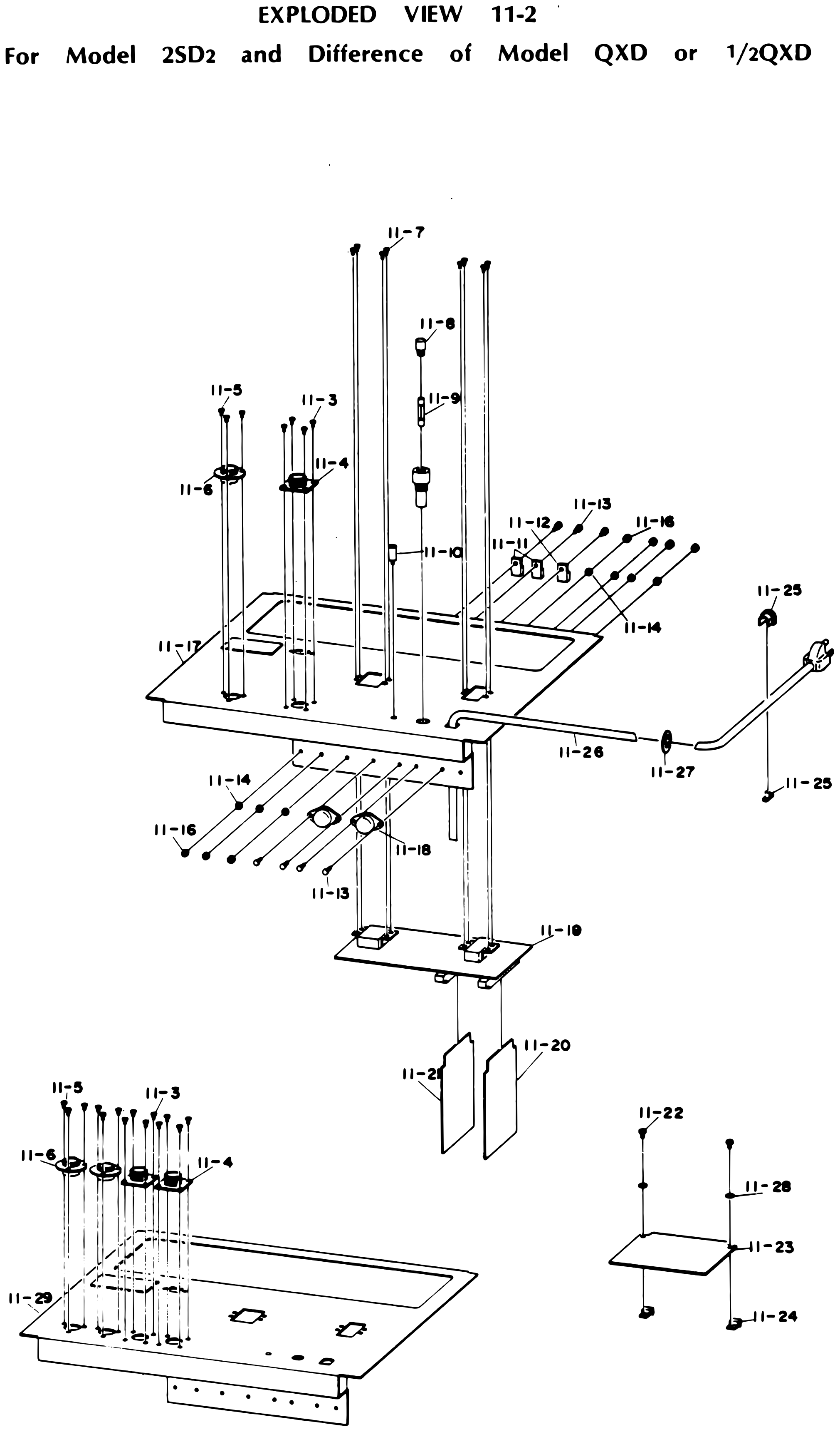 ⤢ zoomEXPLODED VIEW 11-2 For Model 2SD₂ and Difference of Model QXD or ½QXD: the connector panel with one pair of connectors, the fuse holder and fuse, the earth terminal, transistors and power supply IC, the power cord with its cord stoppers and spacer, the mother board below with its two plug-in P.C.B.s, the control P.C.B. at lower right, and, at lower left, the differing connector panel with two pairs of connectors · Redrawn as vector — zooms cleanly ·
PARTS LIST 12-1 For Model 8SD↑ TOP
| Ref. No. | Description | Parts No. | Notes |
|---|---|---|---|
| 12-1 | Knob | NB-31-035 | |
| 12-2 | Set Screw | EZ-09-M3x5 | |
| 12-3 | Spacer | TY-100-031 | |
| 12-4 | Knob | NB-31-036 | |
| 12-5 | Spacer | TY-100-042 | |
| 12-6 | Screw | EZ-09-M3x8 | |
| 12-7 | Display Washer | TY-800-021 | |
| 12-8 | Sheet | TY-800-017 | |
| 12-9 | AMPL Display Panel | AF-237-002 |
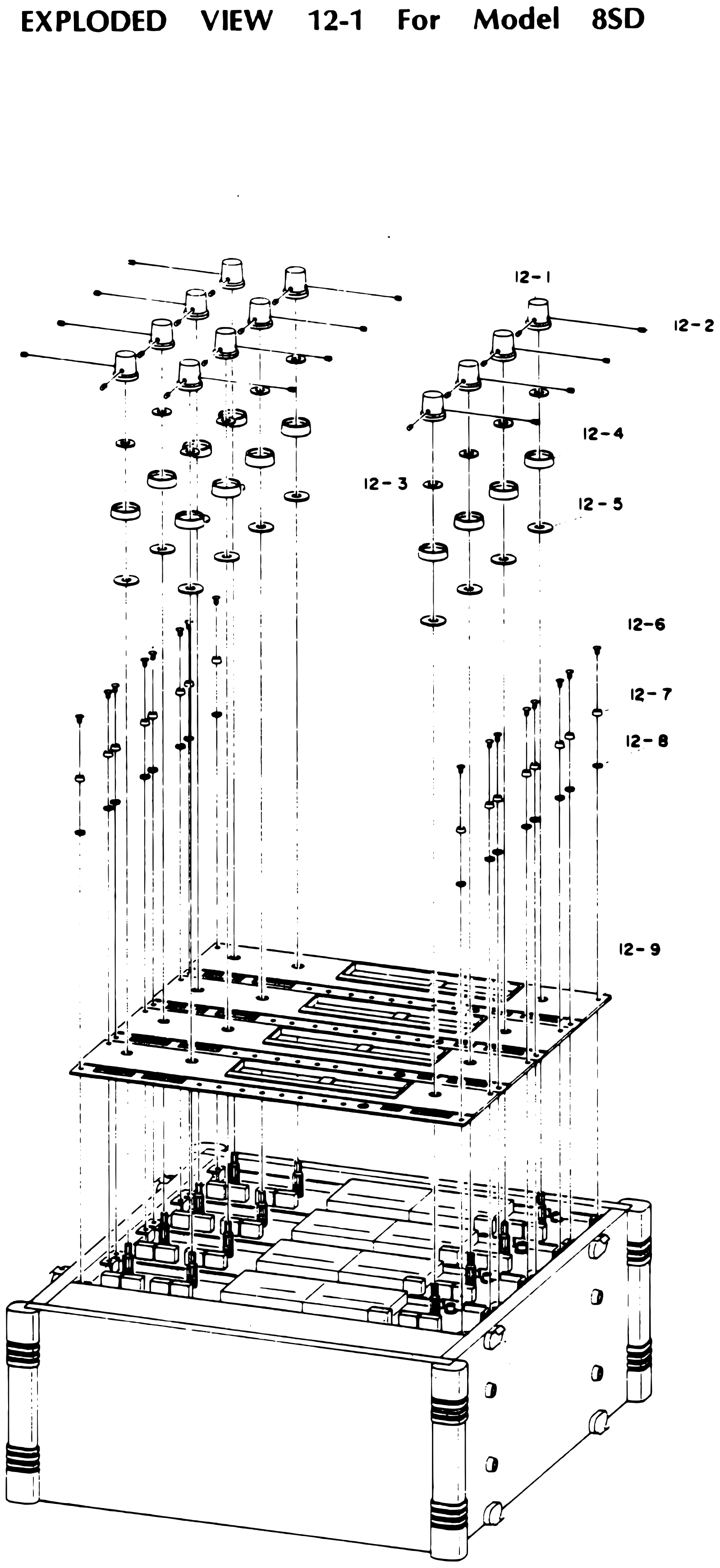 ⤢ zoomEXPLODED VIEW 12-1 For Model 8SD: twelve stacked knobs with their set screws and spacers above the amplifier display panel, the screws, display washers and sheets that hold it, and the amplifier in its case below · Redrawn as vector — zooms cleanly ·
PARTS LIST 12-2 For Model QXD or ½QXD↑ TOP
| Ref. No. | Description | Parts No. | Notes |
|---|---|---|---|
| 12-1 | Knob | NB-31-035 | |
| 12-2 | Set Screw | EZ-09-M3x5 | |
| 12-3 | Spacer | TY-100-031 | |
| 12-4 | Knob | NB-31-036 | |
| 12-5 | Spacer | TY-100-042 | |
| 12-6 | Screw | EZ-09-M3x8 | |
| 12-7 | Display Washer | TY-800-021 | |
| 12-8 | Sheet | TY-800-017 | |
| 12-9 | ANPL Display Panel | AF-237-002 |
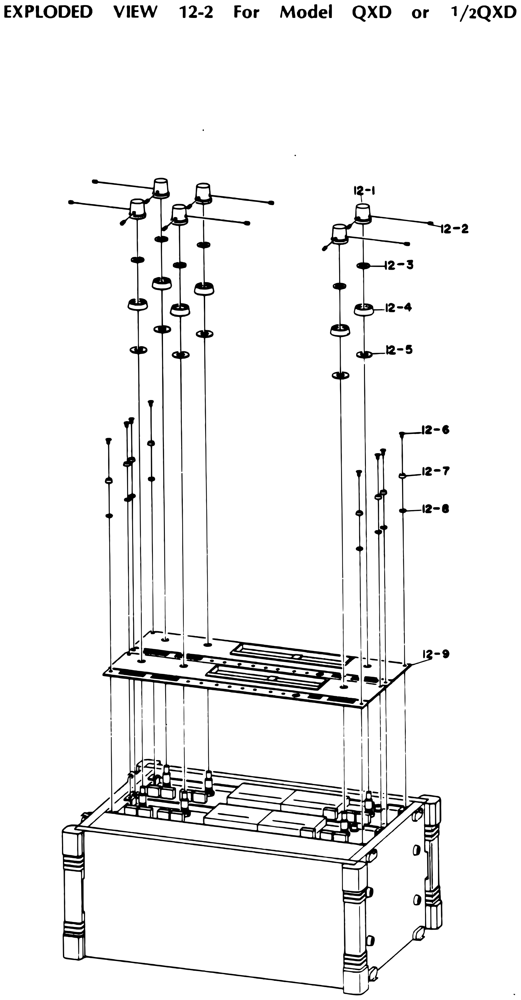 ⤢ zoomEXPLODED VIEW 12-2 For Model QXD or ½QXD: six stacked knobs with their set screws and spacers above the amplifier display panel, the screws, display washers and sheets that hold it, and the amplifier in its case below · Redrawn as vector — zooms cleanly ·
PARTS LIST 12-3 For Model 2SD₂↑ TOP
| Ref. No. | Description | Parts No. | Notes |
|---|---|---|---|
| 12-1 | Knob | NB-31-035 | |
| 12-2 | Set Screw | EZ-09-M3x5 | |
| 12-3 | Spacer | TY-100-031 | |
| 12-4 | Knob | NB-31-036 | |
| 12-5 | Spacer | TY-100-042 | |
| 12-6 | Screw | EZ-09-M3x8 | |
| 12-7 | Display Washer | TY-800-021 | |
| 12-8 | Sheet | TY-800-017 | |
| 12-9 | AMPL Display Panel | AF-237-002 |
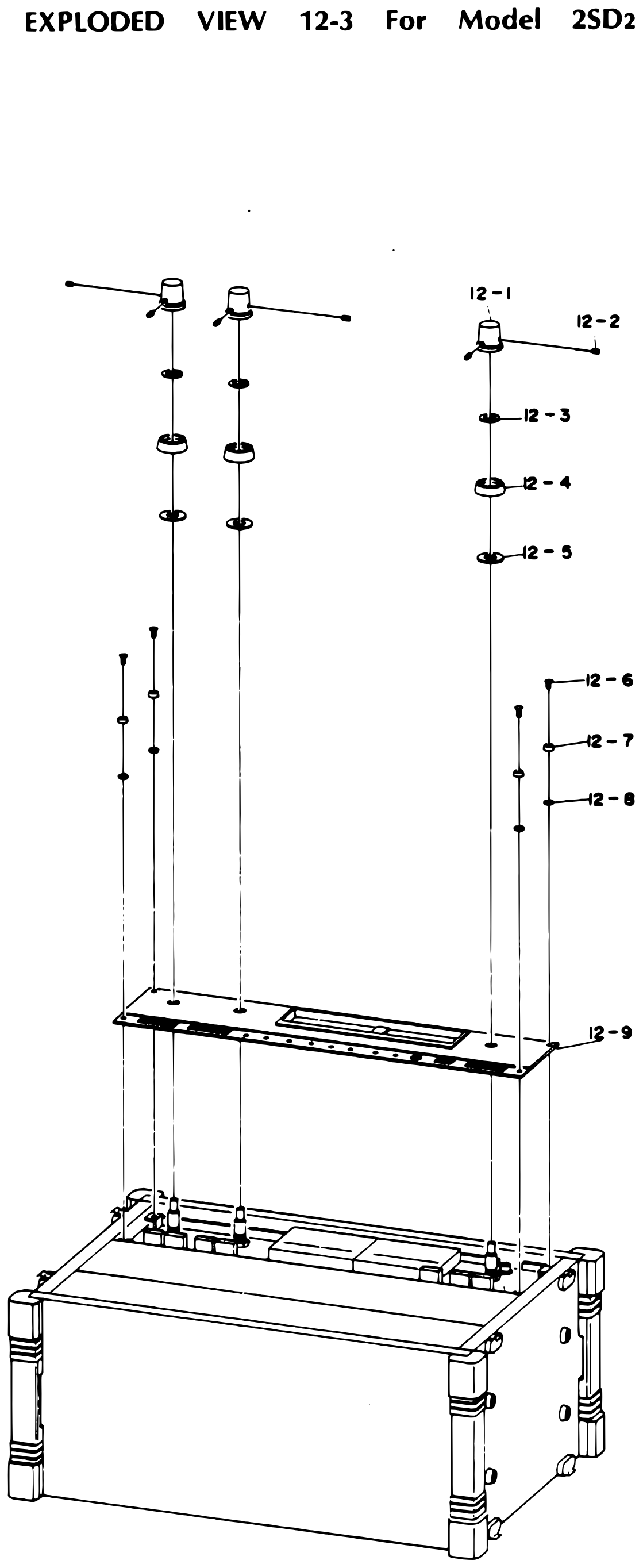 ⤢ zoomEXPLODED VIEW 12-3 For Model 2SD₂: three stacked knobs with their set screws and spacers above the amplifier display panel, the screws, display washers and sheets that hold it, and the amplifier in its case below · Redrawn as vector — zooms cleanly ·
PARTS LIST 13-1 For Model 8SD↑ TOP
| Ref. No. | Description | Parts No. | Notes |
|---|---|---|---|
| 13-1 | Wood Screw | EZ-09-M3.5x20 | |
| 13-2 | Protector | CS-264-005 | |
| 13-3 | Screw | EZ-09-M3x25 | |
| 13-4 | Display Washer | TY-800-021 | |
| 13-5 | Sheet | TY-800-017 | |
| 13-6 | Case Top Board | CS-261-004 | |
| 13-7 | Case Side Board | CS-264-004 | |
| 13-8 | Display Washer | TY-800-014 | |
| 13-9 | Latch | CA-39-C-15 | |
| 13-10 | Wood Screw | EZ-09-M3.1x16 | |
| 13-11 | Cap Screw | EZ-09-M4x25 |
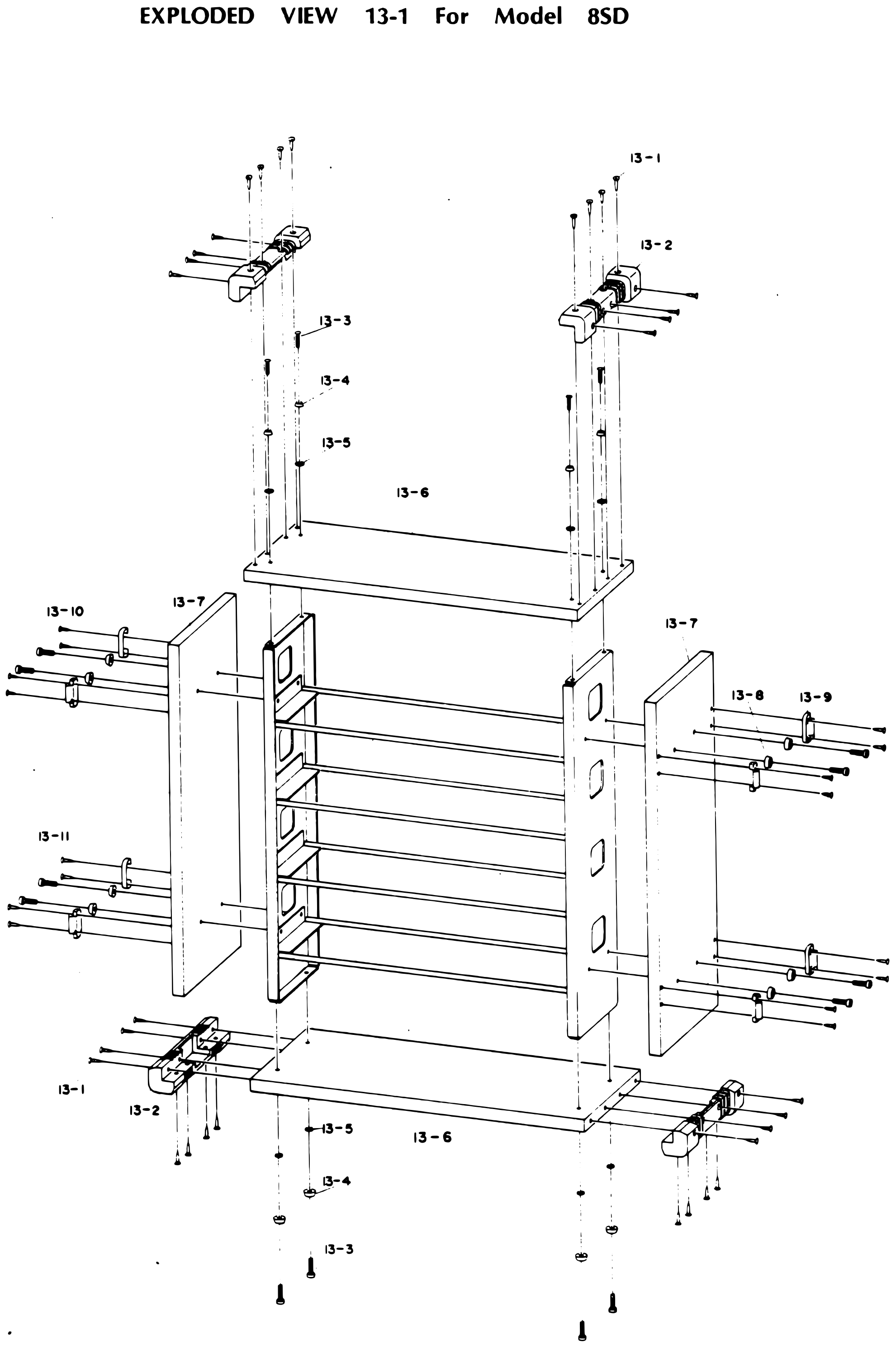 ⤢ zoomEXPLODED VIEW 13-1 For Model 8SD: the amplifier case pulled apart: the top and bottom boards with their screws, display washers and sheets, the corner protectors and their wood screws, and the two side boards with their latches, display washers, wood screws and cap screws, around the amplifier frame · Redrawn as vector — zooms cleanly ·
PARTS LIST 13-2 For Model 2SD₂, QXD or ½QXD↑ TOP
| Ref. No. | Description | Parts No. | Notes |
|---|---|---|---|
| 13-1 | Wood Screw | EZ-09-M3.5x20 | |
| 13-2 | Protector | CS-264-005 | |
| 13-3 | Screw | EZ-09-M3x25 | |
| 13-4 | Display Washer | TY-800-021 | |
| 13-5 | Sheet | TY-800-017 | |
| 13-6 | Case Top Board | CS-261-004 | |
| 13-7 | Case Side Board | CS-263-004 | |
| 13-8 | Display Washer | TY-800-014 | |
| 13-9 | Latch | CA-39-C-15 | |
| 13-10 | Wood Screw | EZ-09-M3.1x16 | |
| 13-11 | Cap Screw | EZ-09-M4x25 |
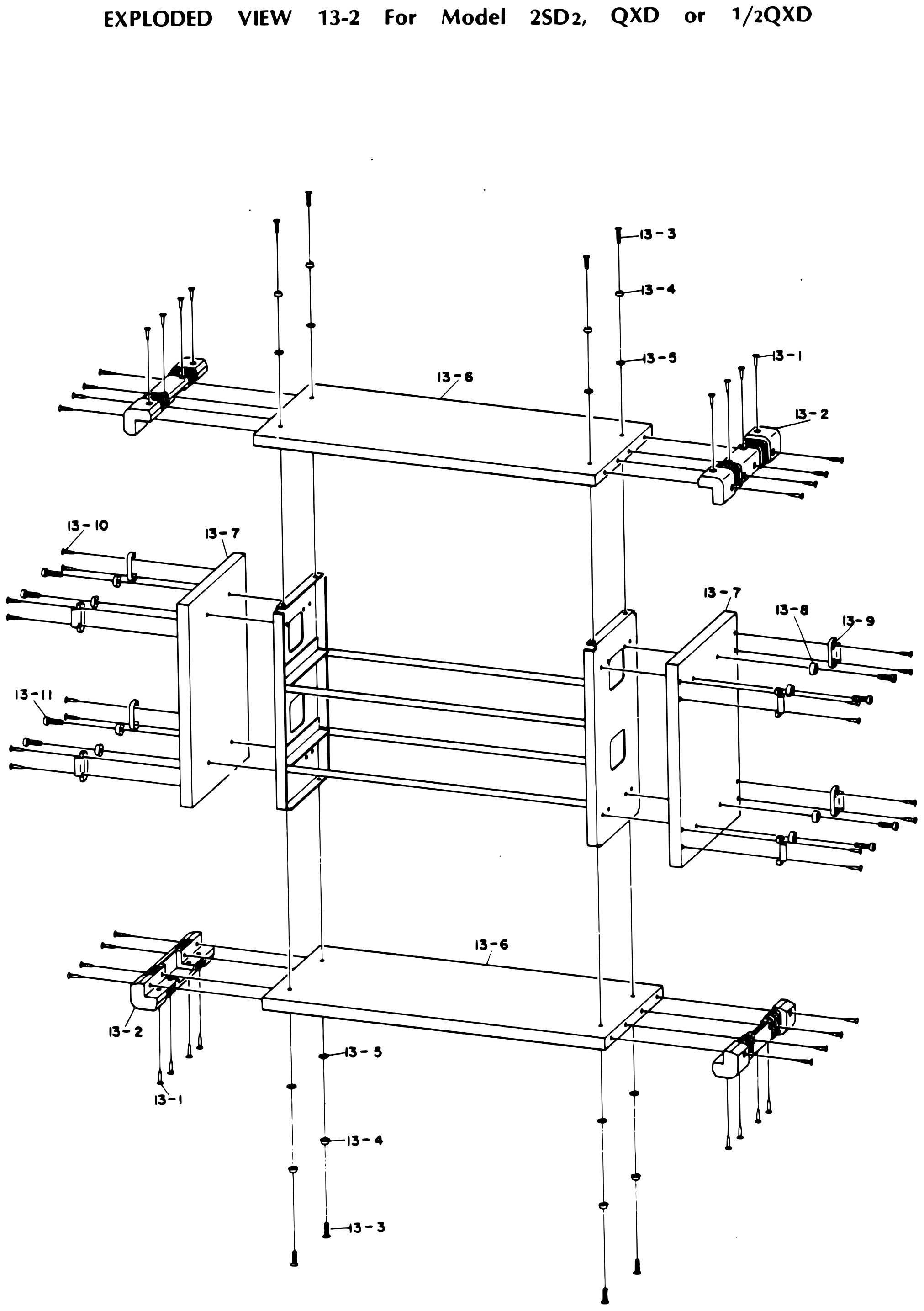 ⤢ zoomEXPLODED VIEW 13-2 For Model 2SD₂, QXD or ½QXD: the shorter amplifier case pulled apart: the top and bottom boards with their screws, display washers and sheets, the corner protectors and their wood screws, and the two side boards with their latches, display washers, wood screws and cap screws, around the amplifier frame · Redrawn as vector — zooms cleanly ·
PARTS LIST 14-1 For Model 8SD↑ TOP
| Ref. No. | Description | Parts No. | Notes |
|---|---|---|---|
| 14-1 | Screw | EZ-09-M3x6 | |
| 14-2 | Amplifier | AF-237 | |
| 14-3 | Screw | EZ-09-M3x8 | |
| 14-4 | Display Washer | TY-800-021 | |
| 14-5 | Sheet | TY-800-017 | |
| 14-6 | Blank Panel | CS-261-005 | |
| 14-7 | Stud | ST-090 | |
| 14-8 | Frame Stud | CS0251-007 | |
| 14-9 | Amplifier Frame | CS-261-001 | |
| 14-10 | Screw | EZ-09-M3x6 | |
| 14-11 | Cover | CS-261-006 | |
| 14-12 | Plain Washer | EZ-09-M3 | |
| 14-13 | Screw | EZ-09-M3x6 |
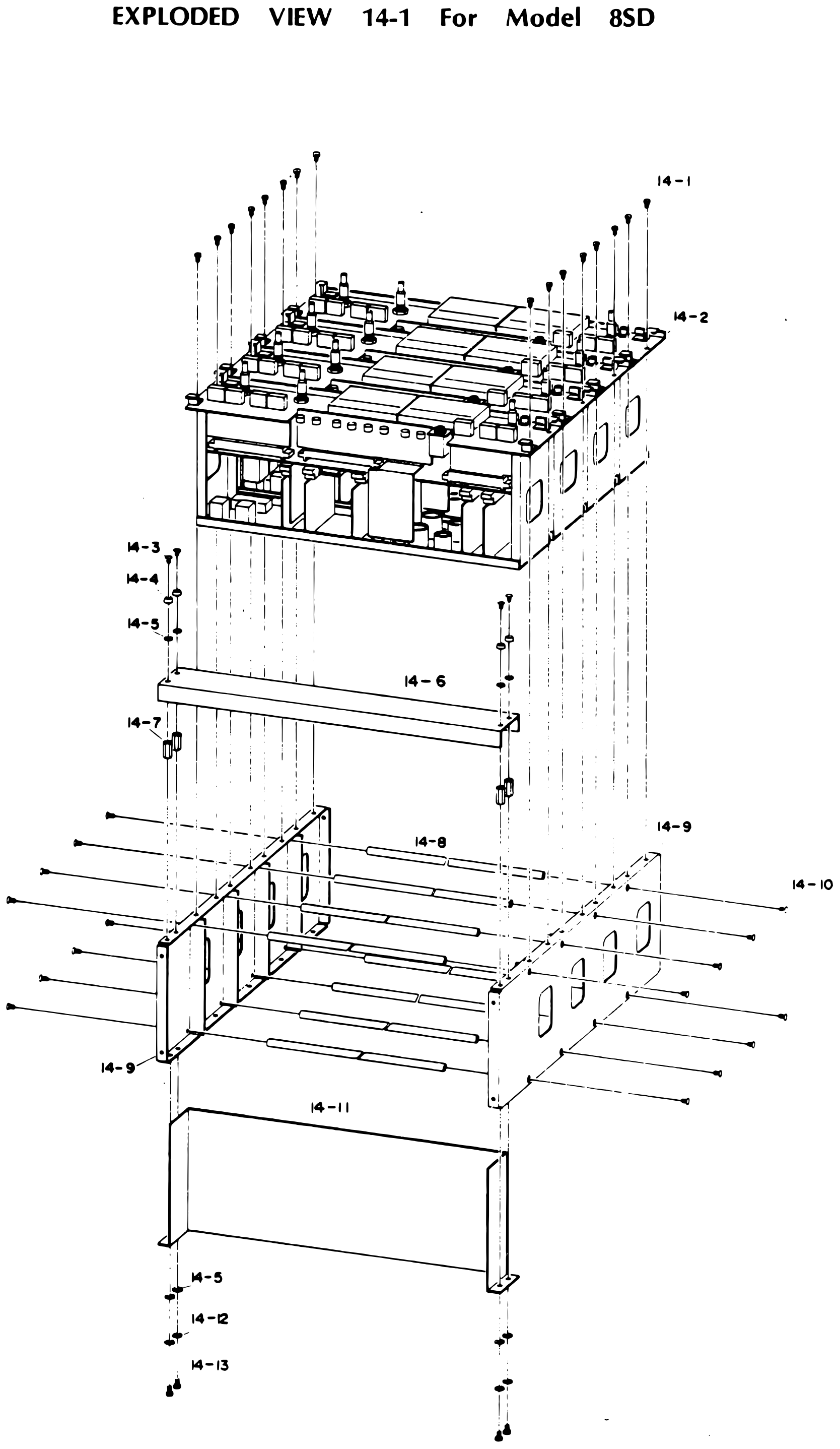 ⤢ zoomEXPLODED VIEW 14-1 For Model 8SD: the amplifier screwed down into the amplifier frame, the blank panel across the front on its screws, display washers, sheets and studs, the frame studs between the frame sides, and the cover underneath on plain washers and screws · Redrawn as vector — zooms cleanly ·
PARTS LIST 14-2 For Model QXD or ½QXD↑ TOP
| Ref. No. | Description | Parts No. | Notes |
|---|---|---|---|
| 14-1 | Screw | EZ-09-M3x6 | |
| 14-2 | Amplifier | AF-237 | |
| 14-3 | Screw | EZ-09-M3x8 | |
| 14-4 | Display Washer | TY-800-021 | |
| 14-5 | Sheet | TY-800-017 | |
| 14-6 | Blank Panel | CS-261-005 | |
| 14-7 | Stud | ST-090 | |
| 14-8 | Frame Stud | CS-0251-007 | |
| 14-9 | Amplifier Frame | CS-263-001 | |
| 14-10 | Screw | EZ-09-M3x6 | |
| 14-11 | Cover | CS-261-006 | |
| 14-12 | Plain Washer | EZ-09-M3 | |
| 14-13 | Screw | EZ-09-M3x6 |
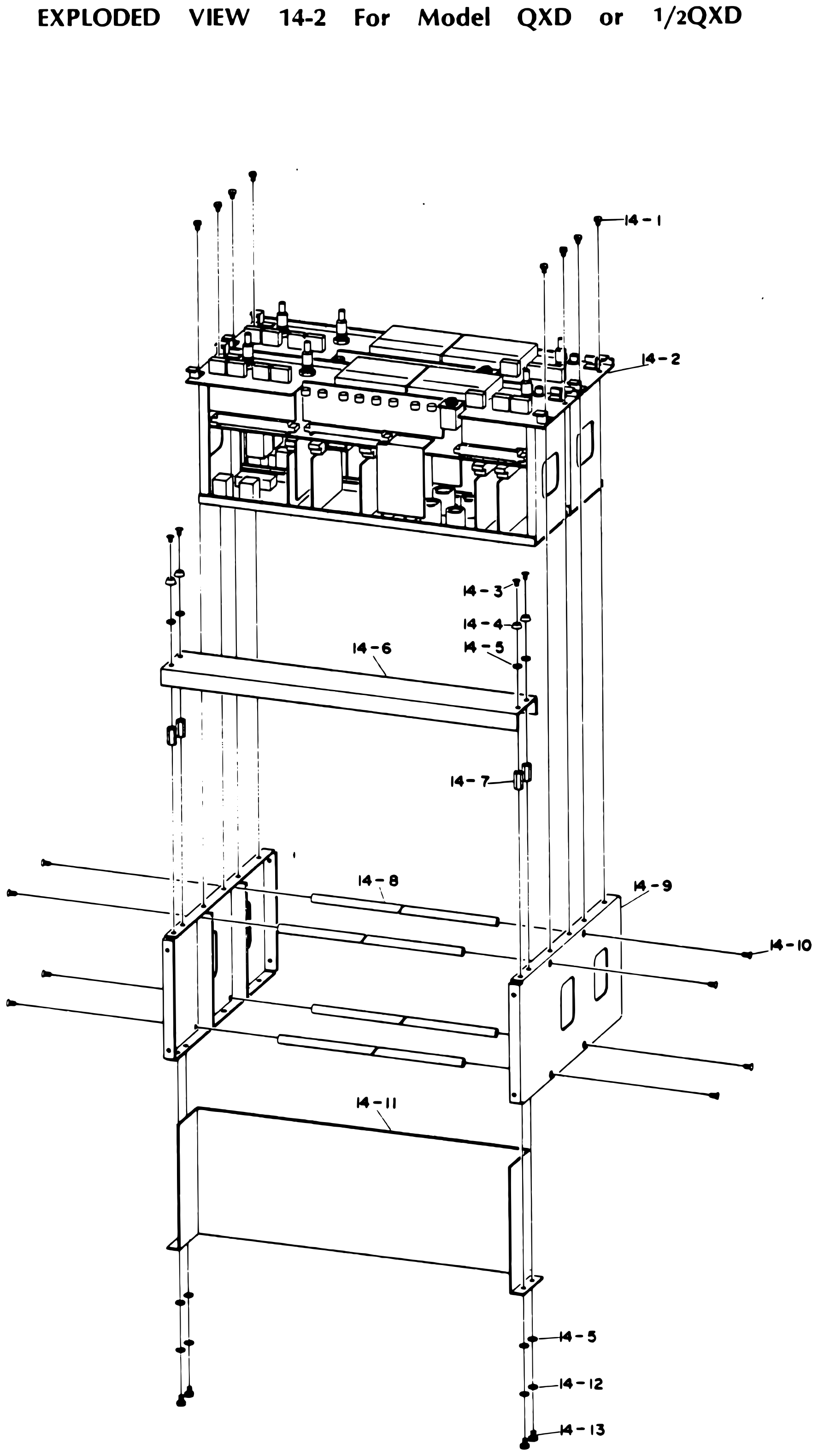 ⤢ zoomEXPLODED VIEW 14-2 For Model QXD or ½QXD: the narrower amplifier screwed down into the amplifier frame, the blank panel across the front on its screws, display washers, sheets and studs, the frame studs between the frame sides, and the cover underneath on plain washers and screws · Redrawn as vector — zooms cleanly ·
PARTS LIST 14-3 For Model 2SD₂↑ TOP
| Ref. No. | Description | Parts No. | Notes |
|---|---|---|---|
| 14-1 | Screw | EZ-09-M3x6 | |
| 14-2 | Amplifier | AF-237 | |
| 14-3 | Screw | EZ-09-M3x8 | |
| 14-4 | Display Washer | TY-800-021 | |
| 14-5 | Sheet | TY-800-017 | |
| 14-6 | Blank Panel | CS-261-005 | |
| 14-7 | Stud | ST-090 | |
| 14-8 | Frame Stud | CS-0251-007 | |
| 14-9 | Amplifier Frame | CS-263-001 | |
| 14-10 | Screw | EZ-09-M3x6 | |
| 14-11 | Cover | CS-261-006 | |
| 14-12 | Plain Washer | EZ-09-M3 | |
| 14-13 | Screw | EZ-09-M3x6 | |
| 14-14 | Blank Panel | CS-261-005 | |
| 14-15 | Blank Panel | CS-275-002 |
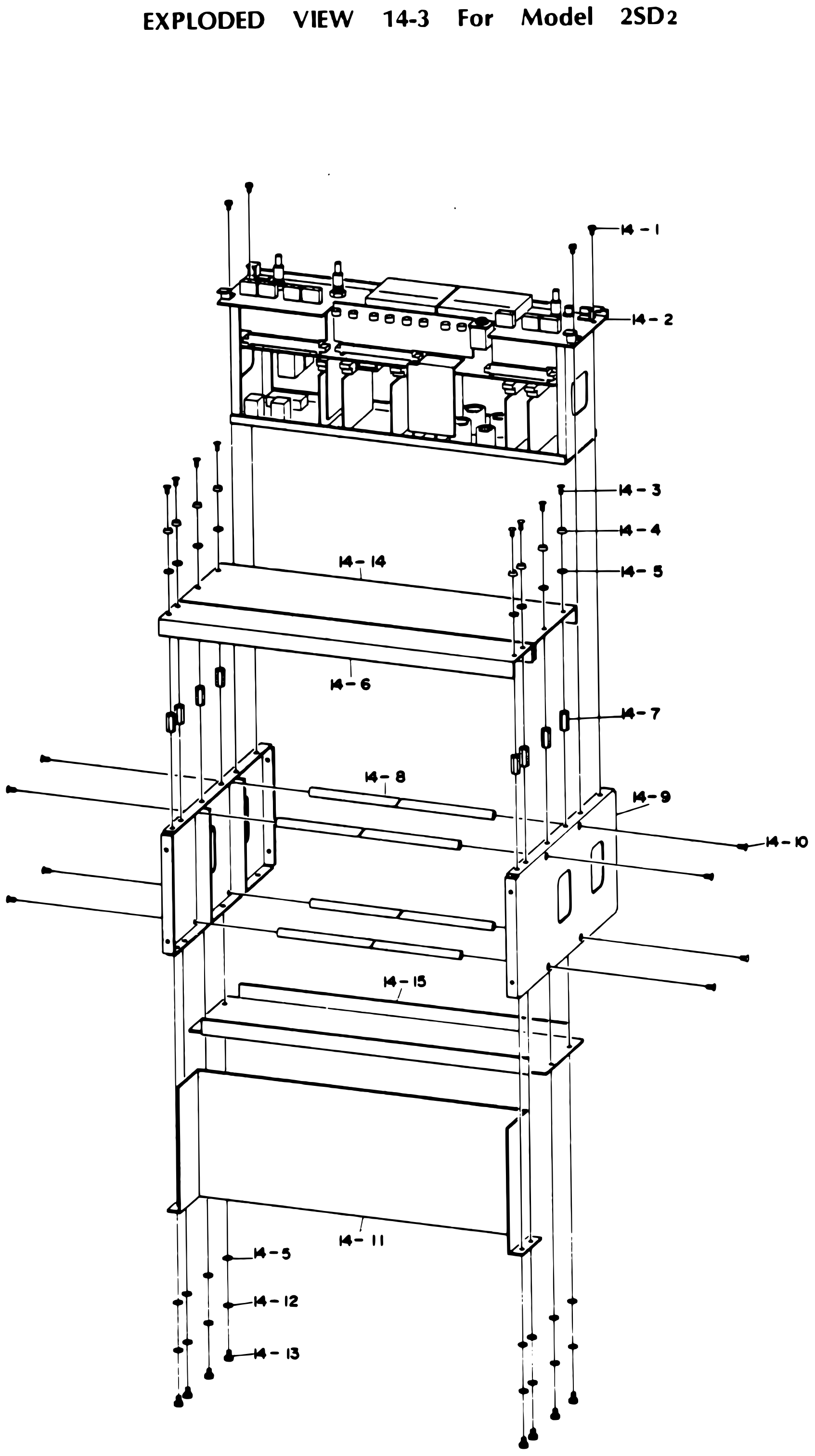 ⤢ zoomEXPLODED VIEW 14-3 For Model 2SD₂: the smaller amplifier screwed down into the amplifier frame, two blank panels stacked across the front on their screws, display washers, sheets and studs, the frame studs between the frame sides, a further blank panel below the frame, and the cover underneath on plain washers and screws · Redrawn as vector — zooms cleanly ·
PARTS LIST 15↑ TOP
| Ref. No. | Description | Parts No. | Notes |
|---|---|---|---|
| 15-1 | Knob | NB-31-035 | |
| 15-2 | Set Screw | EZ-09-M3x5 | |
| 15-3 | Spacer | TY-100-031 | |
| 15-4 | Knob | NB-31-036 | |
| 15-5 | Spacer | TY-100-042 | |
| 15-6 | Push Button | NB-19-4094(302) | |
| 15-7 | Push Button B | NB-19-4094B | |
| 15-8 | Variable Resistor Escutcheon | TY-100-010 | |
| 15-9 | Push Button A | NB-19-4094A | |
| 15-10 | Display Panele | AF-237-002 | |
| 15-11 | VU Meter | MT-11-023 | |
| 15-12 | Lamp Assembly | PL-19-005 | |
| 15-13 | VU PCB Assembly | PA-401 | |
| 15-14 | Spring Washer | EZ-09-M3 | |
| 15-15 | Screw | EZ-09-M3x6 | |
| 15-16 | Screw | EZ-09-M3x6 | |
| 15-17 | Blind | TY-900-031 | |
| 15-18 | Blind | TY-900-029 | |
| 15-19 | Screw | EZ-09-M2.6x4 | |
| 15-20 | Amplifier Mounting Base | AF-234-002 | |
| 15-21 | Switch PCB Assembly B | PA-305 | |
| 15-22 | Stereo Jack | CN-09-LJ-109 | |
| 15-23 | Switch PCB Assembly A | PA-304 | |
| 15-24 | Nut | EZ-09-M3 | |
| 15-25 | Slide Switch C | SW-39-SL242B4 | |
| 15-26 | Shielding Plate A | AF-198-002 | |
| 15-27 | Amplifier Chassis | AF-234-004 | |
| 15-28 | Cord Stopper | EZ-09-SN-6A | |
| 15-29 | Screw | EZ-09-M3x10 | |
| 15-30 | VR PCB Assembly | PA-373 | |
| 15-31 | Connector | CN-09-SRC06A16-10P | |
| 15-32 | Mother PCB Assembly | PA-345 | |
| 15-33 | Connector | CN-09-16-P4F | |
| 15-34 | Reproduce Amplifier PCB Assembly | PA-372 | |
| 15-35 | SEL REP Amplifier PCB Assembly | PA-375 | |
| 15-36 | Record Amplifier PCB Assembly | PA-371 | |
| 15-37 | Test OSC PCB Assembly | PA-379 | |
| 15-38 | BIAS Buffer Amprifier PCB Assembly | PA-376(8SD) PA-419(½QXD) PA391(QXD) PA-418(2SD₂) | |
| 15-39 | Connector | CN-09-QS-10M(I) | |
| 15-40 | Jack | CN-09-LJ-110-1-2 | |
| 15-41 | Shielding Plate B | AF-198-003 | |
| 15-42 | Rear Panel | AF-237-004 | |
| 15-43 | Shielding Plate C | AF-198-004 | |
| 15-44 | Screw | EZ-09--M3x10 | |
| 15-45 | Connector | CN-09-MR-8M | |
| 15-46 | Screw | EZ-09-2.6x8 | |
| 15-47 | Sheet | TY-800-017 | |
| 15-48 | Plain Washer | EZ-09-M3 | |
| 15-49 | Screw | EZ-09-M3x8 | |
| 15-50 | Socket | CN-09-XLR-3-31 | |
| 15-51 | Socket | CN-09-XLR-3-32 | |
| 15-52 | Screw | EZ-09-M3x6 |
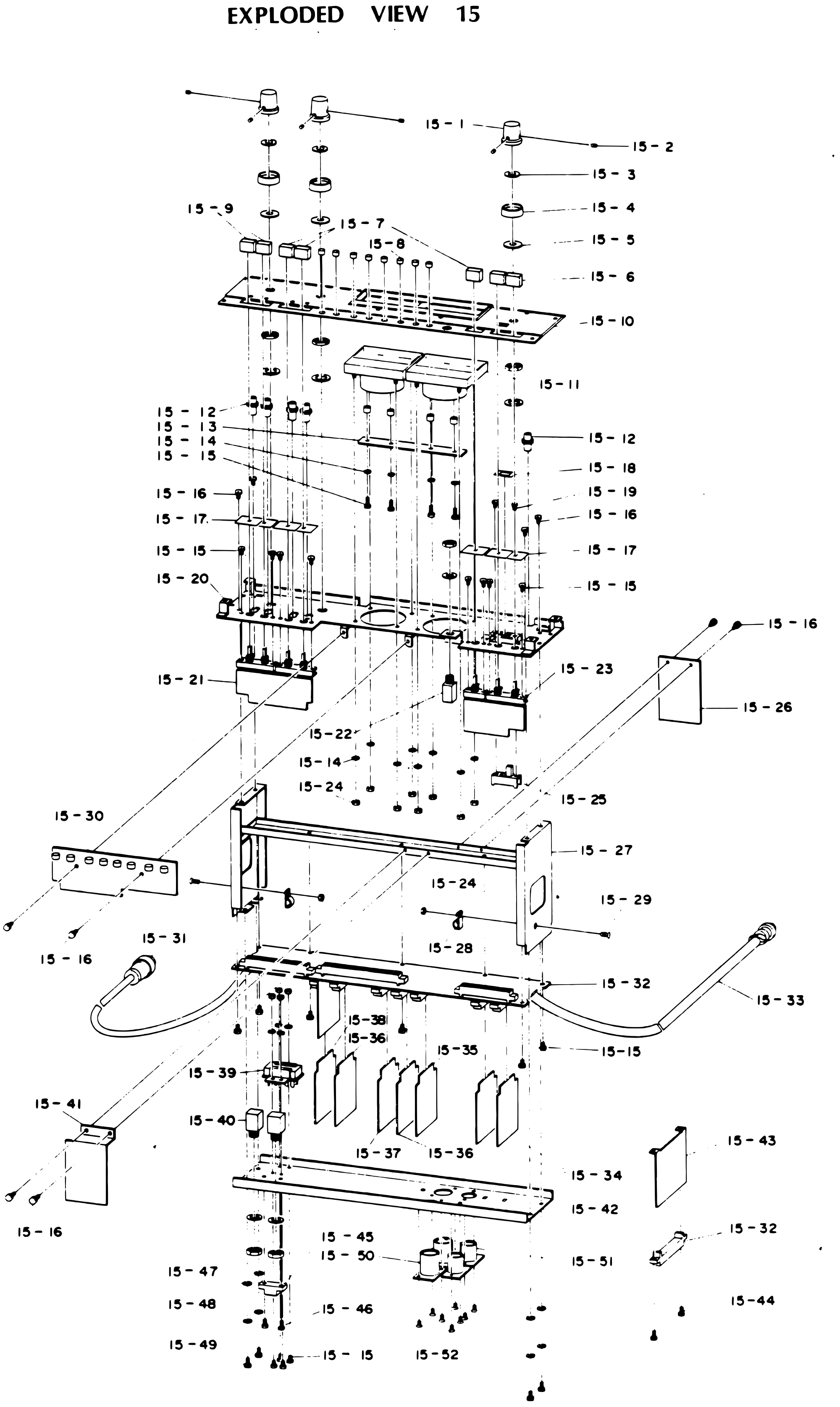 ⤢ zoomEXPLODED VIEW 15: the amplifier taken apart from top to bottom: the knobs, push buttons and variable resistor escutcheon above the display panel, the VU meters, lamp assemblies and VU P.C.B. below it, the blinds and the amplifier mounting base with switch P.C.B. assemblies A and B, the stereo jack and slide switch, the amplifier chassis with its shielding plates, the mother P.C.B. with the reproduce, record, SEL REP, test oscillator and bias buffer amplifier P.C.B.s plugged into it, the VR P.C.B. and the two connector cables, and the rear panel at the bottom with its connectors, jacks and XLR sockets · Redrawn as vector — zooms cleanly ·
SIMPLIFIED DIAGRAM FOR 8SD AND QXD (at 1KHZ)↑ TOP
A block diagram of one channel's record and reproduce signal path, marked with the signal level at each stage for a 1 kHz signal; values in parentheses are for the QXD. It runs from the microphone and line inputs through the line input and record output amplifiers to the record head, with the 133 kHz master oscillator and bias buffer amplifier feeding the erase and record heads, and from the reproduce head through the reproduce equalizer and line output amplifiers to the line output, headphone and VU meter, with the sel-rep amplifier and test oscillator alongside.
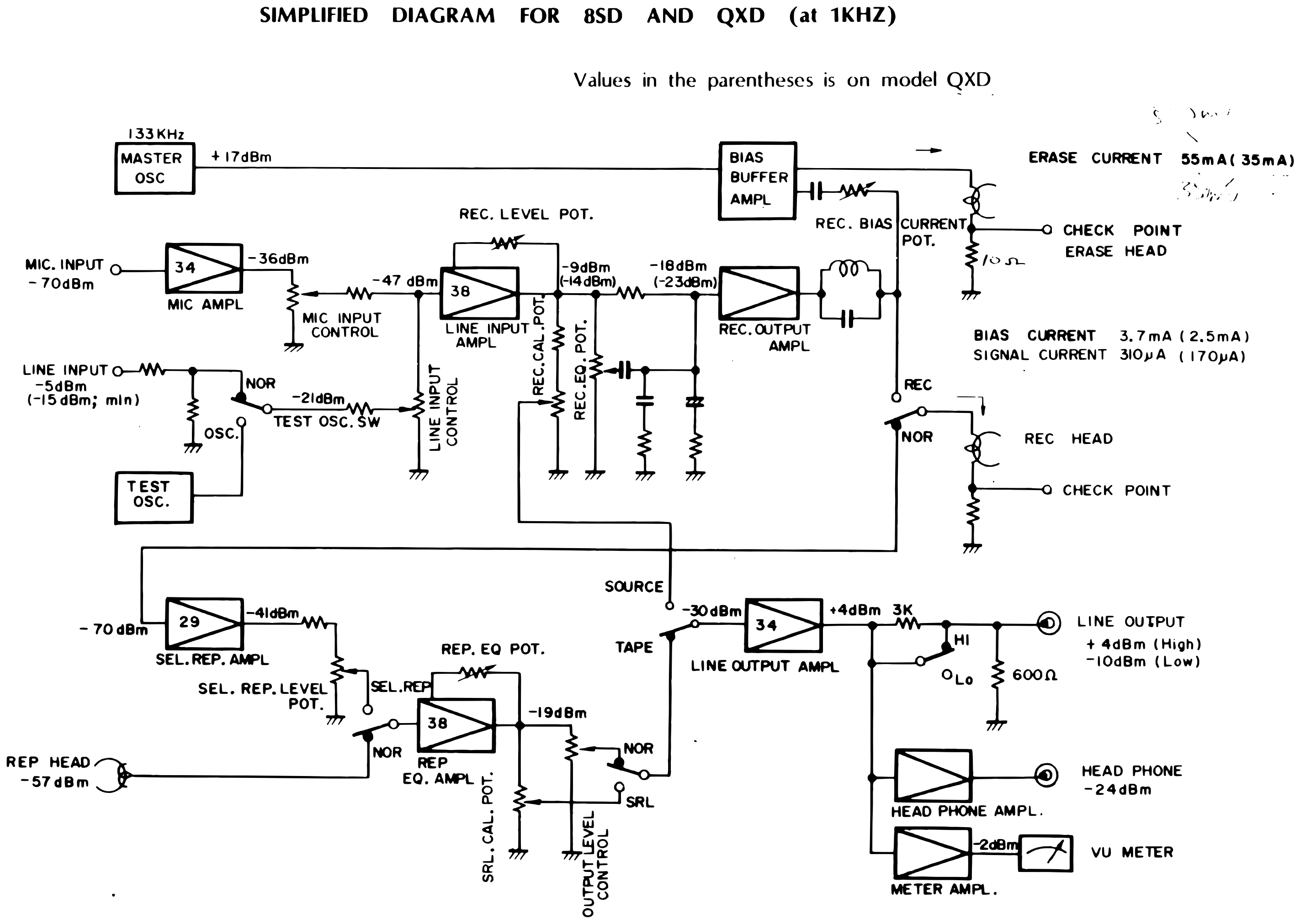 ⤢ zoomSIMPLIFIED DIAGRAM FOR 8SD AND QXD (at 1KHZ): block diagram of the record and reproduce signal path with the signal level marked at each stage, erase and bias current check points, and the line, headphone and meter outputs · Redrawn as vector — zooms cleanly ·
Download the traced vector PDF
RECORD AMPLIFIER UNIT (PA-371)↑ TOP
The record amplifier board (PA-371): a two-transistor microphone preamplifier, a TA7129P line amplifier, and a record output stage with switched equalizer capacitors and a muting FET. The notes list the transistor types and a table of equalizer connections for NAB and CCIR at each speed pair.
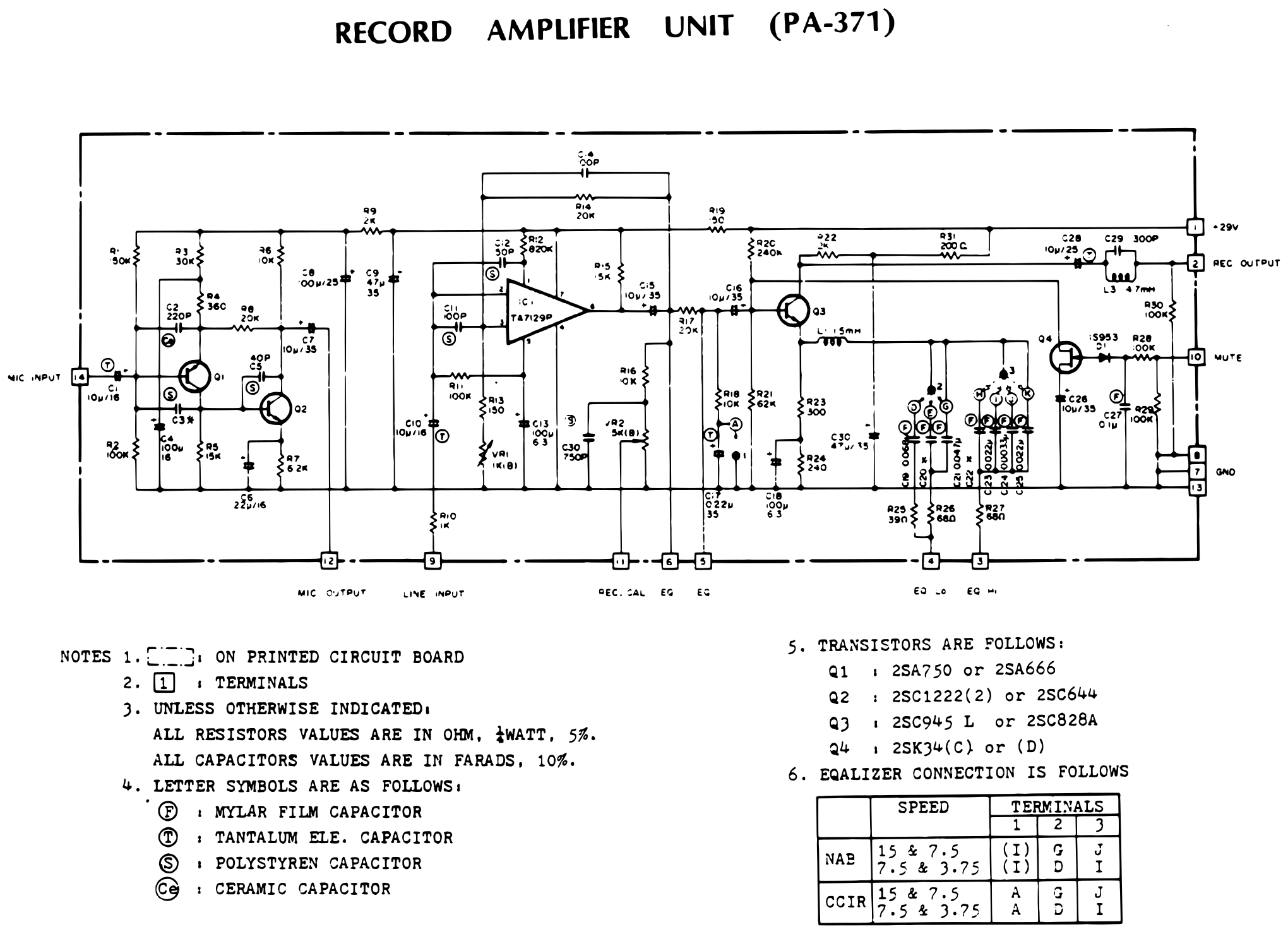 ⤢ zoomRECORD AMPLIFIER UNIT (PA-371): schematic of the microphone preamplifier, line amplifier and record output stage, with notes on transistor types and an NAB/CCIR equalizer connection table · Redrawn as vector — zooms cleanly ·
Download the traced vector PDF
RECORD AMPLIFIER P.C.B Ass'y PA-371 (PM-871A)↑ TOP
Component layout of the record amplifier board PA-371, printed board PM-871A, with the equalizer jumper points lettered A to K.
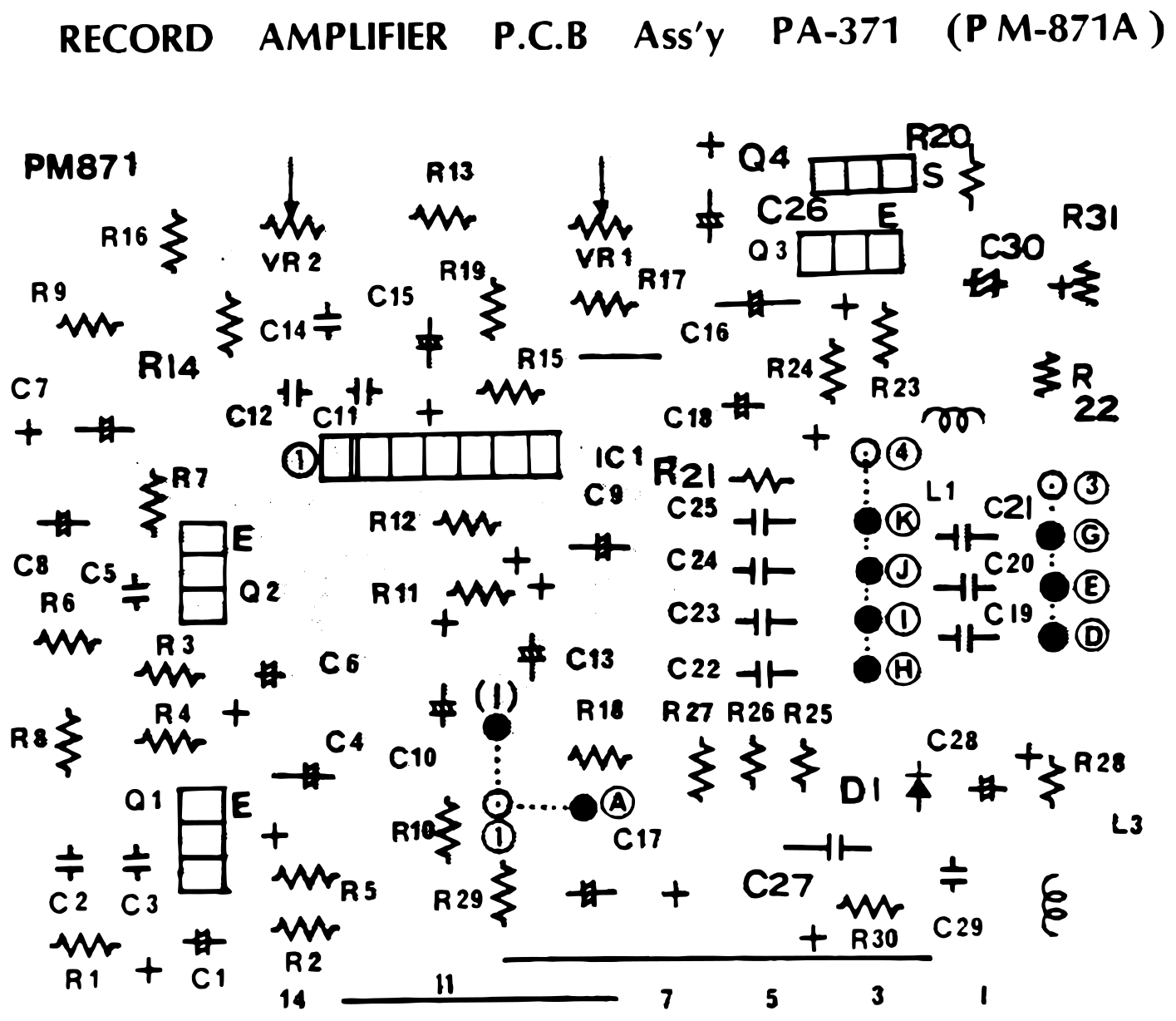 ⤢ zoomRECORD AMPLIFIER P.C.B Ass'y PA-371 (PM-871A): component layout of the record amplifier board · Redrawn as vector — zooms cleanly ·
Download the traced vector PDF
REPRODUCE AMPLIFIER UNIT (PA-372)↑ TOP
The reproduce amplifier board (PA-372): a discrete reproduce preamplifier with FET-switched equalization, a line output amplifier with a complementary output pair and the high/low output level switch, and a transformer-coupled headphone amplifier. The notes list the transistor types.
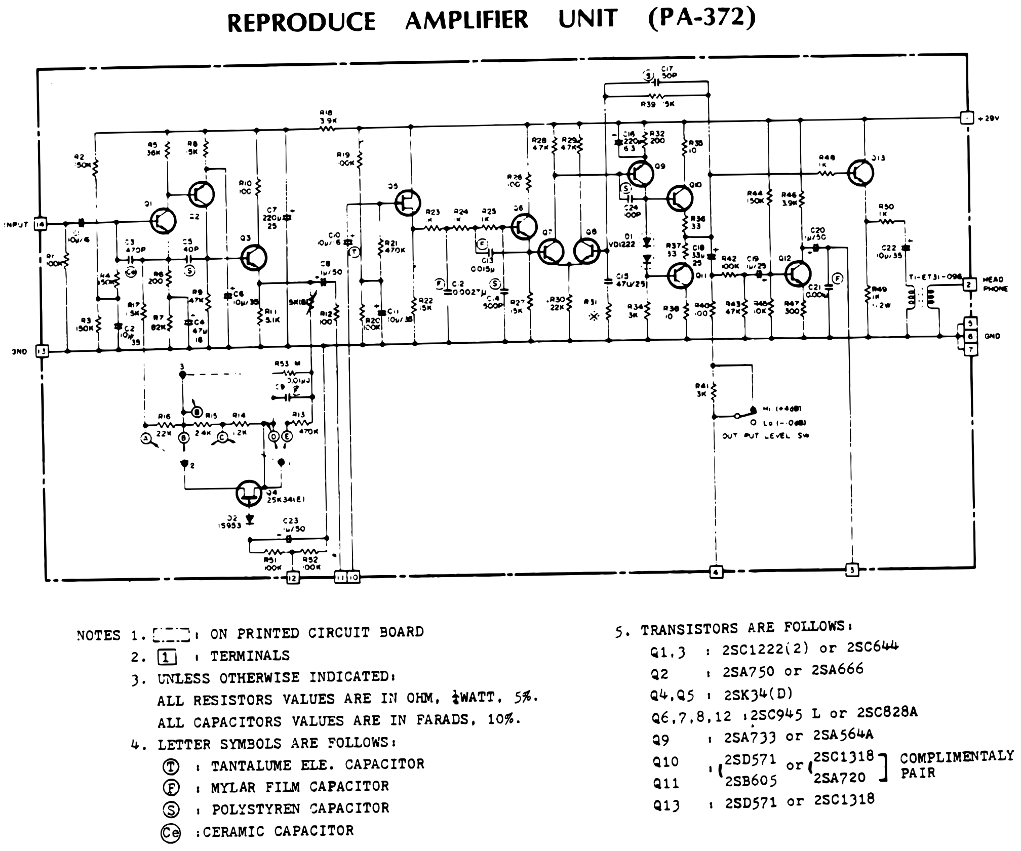 ⤢ zoomREPRODUCE AMPLIFIER UNIT (PA-372): schematic of the reproduce preamplifier and equalizer, line output amplifier with output level switch, and headphone amplifier · Redrawn as vector — zooms cleanly ·
Download the traced vector PDF
REPRODUCE AMPLIFIER P.C.B Ass'y PA-372 (PM-872A)↑ TOP
Component layout of the reproduce amplifier board PA-372, printed board PM-872A, with switch SW1 and headphone transformer T1.
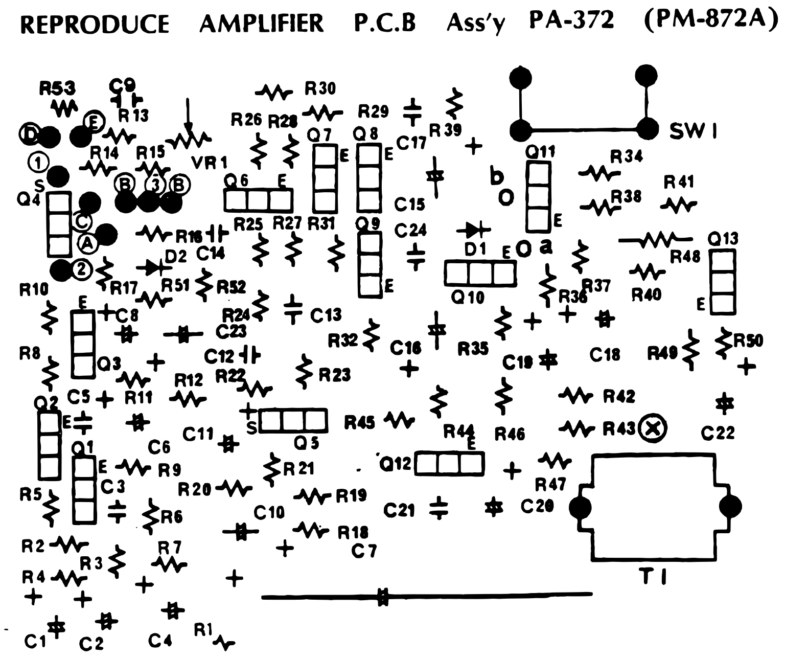 ⤢ zoomREPRODUCE AMPLIFIER P.C.B Ass'y PA-372 (PM-872A): component layout of the reproduce amplifier board · Redrawn as vector — zooms cleanly ·
Download the traced vector PDF
SEL. REP. AMPLIFIER (PA-375)↑ TOP
The sel-rep amplifier board (PA-375): two identical channels, L and R, each a transistor and FET amplifier between RC networks, with an output level pot. The notes list the transistor types.
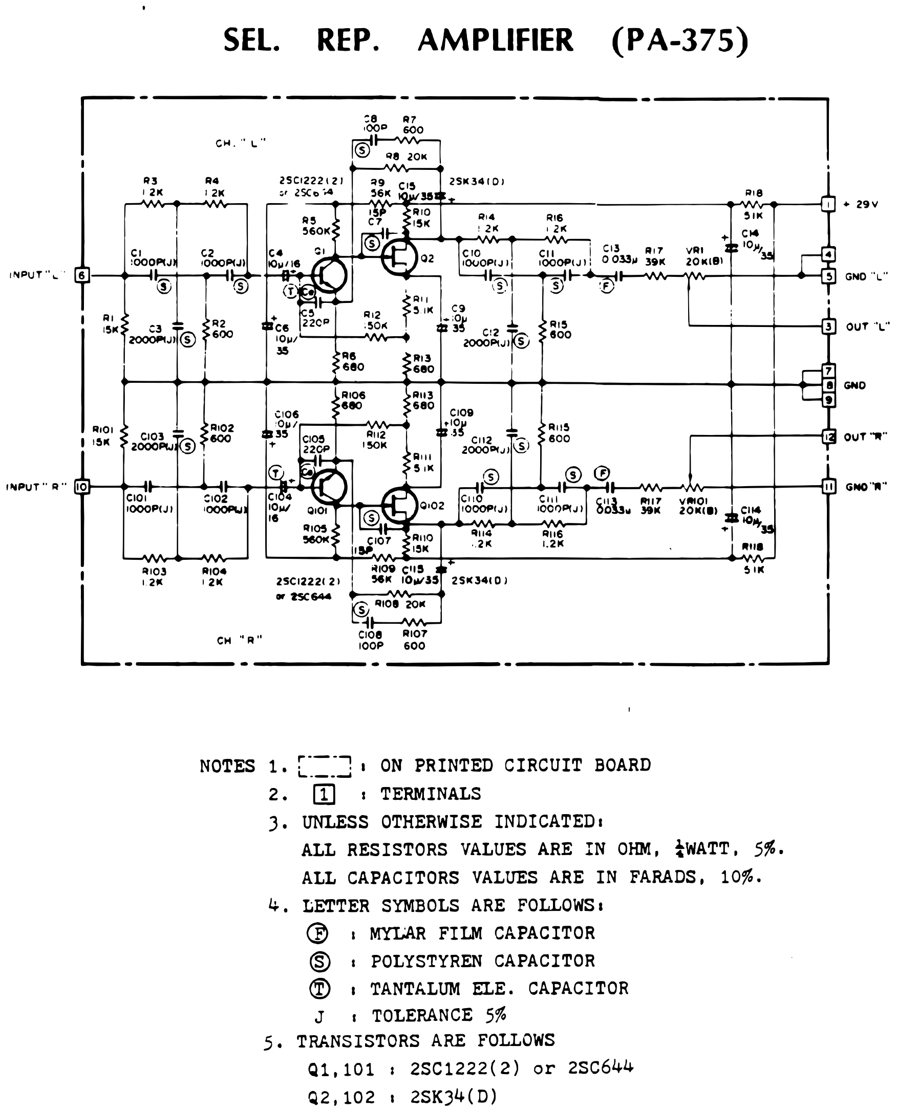 ⤢ zoomSEL. REP. AMPLIFIER (PA-375): schematic of the two-channel sel-rep amplifier · Redrawn as vector — zooms cleanly ·
Download the traced vector PDF
SEL. REP. AMPLIFIER P.C.B. Ass'y PA-375 (PM-874A)↑ TOP
Component layout of the sel-rep amplifier board PA-375, printed board PM-874A, with the R and L channels laid out as mirror images.
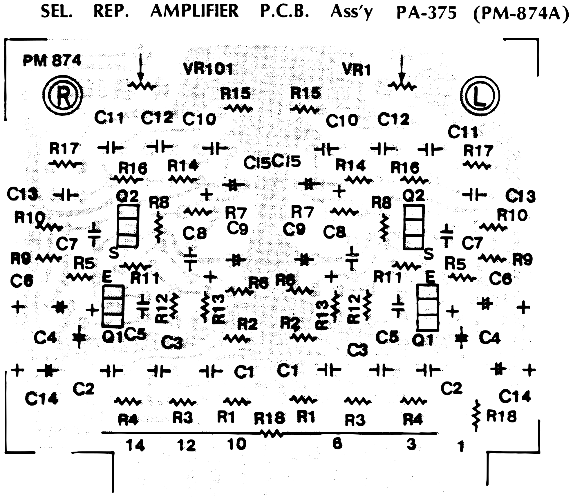 ⤢ zoomSEL. REP. AMPLIFIER P.C.B. Ass'y PA-375 (PM-874A): component layout of the two-channel sel-rep amplifier board · Redrawn as vector — zooms cleanly ·
Download the traced vector PDF
TEST OSCILLATOR UNIT (PA-379)↑ TOP
The test oscillator board (PA-379): a 741 op-amp oscillator with FET amplitude control, and four FET switches that put the oscillator onto the L and R outputs in place of the inputs. The notes list the transistor and diode types.
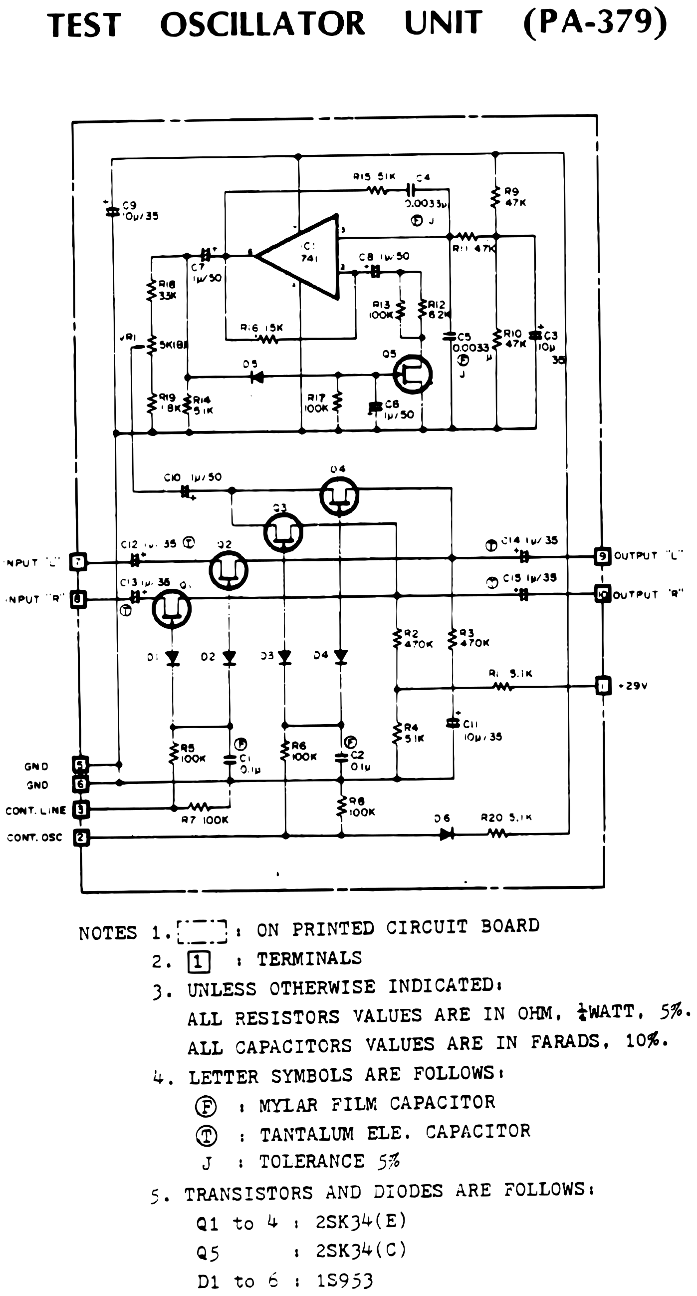 ⤢ zoomTEST OSCILLATOR UNIT (PA-379): schematic of the op-amp oscillator and the FET switches between the inputs and outputs · Redrawn as vector — zooms cleanly ·
Download the traced vector PDF
TEST OSCILLATOR P.C.B. Ass'y PA-379 (PM-878)↑ TOP
Component layout of the test oscillator board PA-379, printed board PM-878.
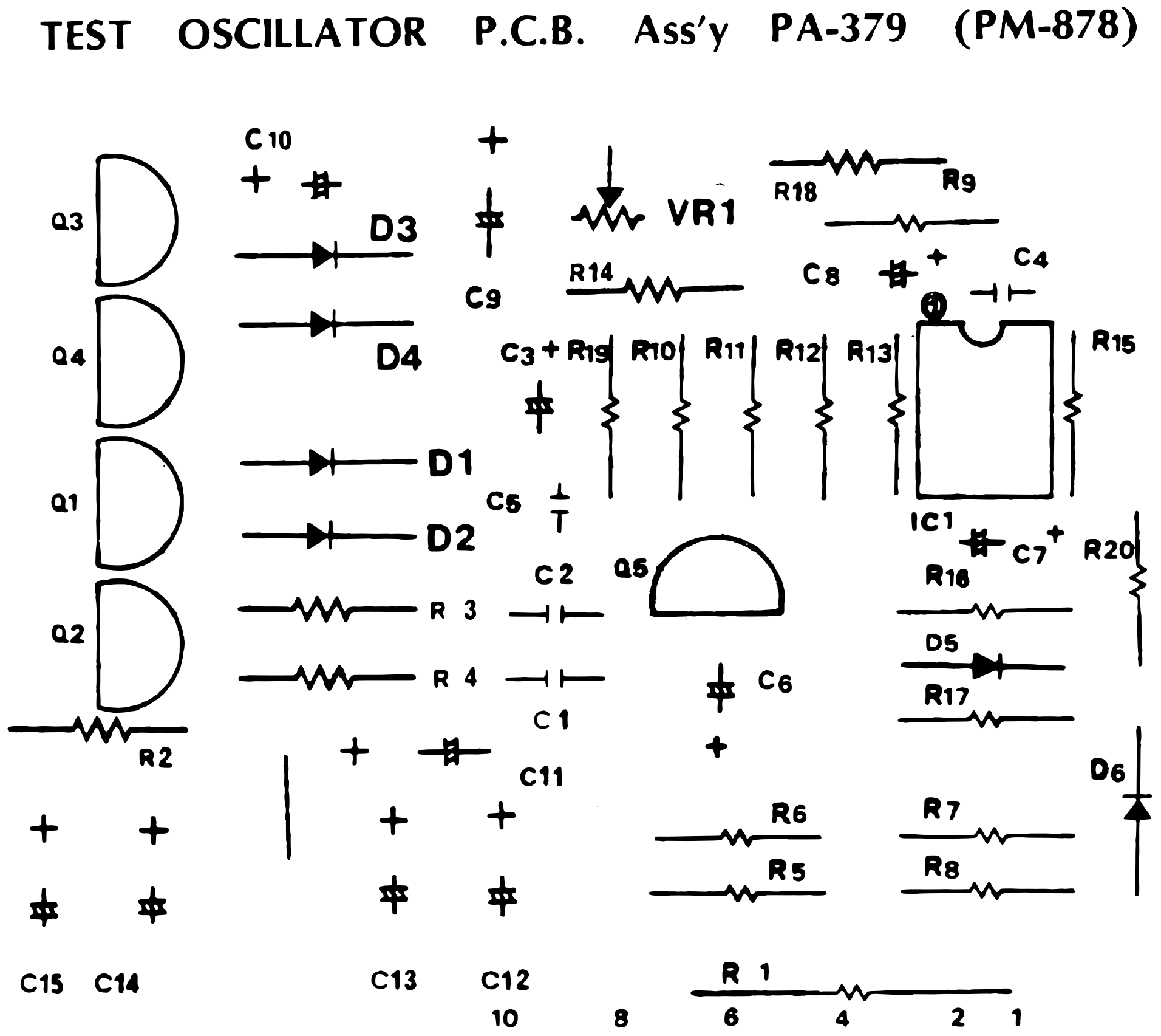 ⤢ zoomTEST OSCILLATOR P.C.B. Ass'y PA-379 (PM-878): component layout of the test oscillator board · Redrawn as vector — zooms cleanly ·
Download the traced vector PDF
BIAS BUFFER AMPLIFIER UNIT PA-418 for 2SD₂ PA-419 for ½QXD PA-391 for QXD PA-376 for 8SD↑ TOP
One schematic for the four versions of the bias buffer amplifier: for each channel, a push-pull transistor stage drives a transformer that delivers the erase and bias outputs, switched by the record command. A table gives what differs between models: the transformers L1 and L101, C8 and C108, and resistors R13, R113, R14 and R114.
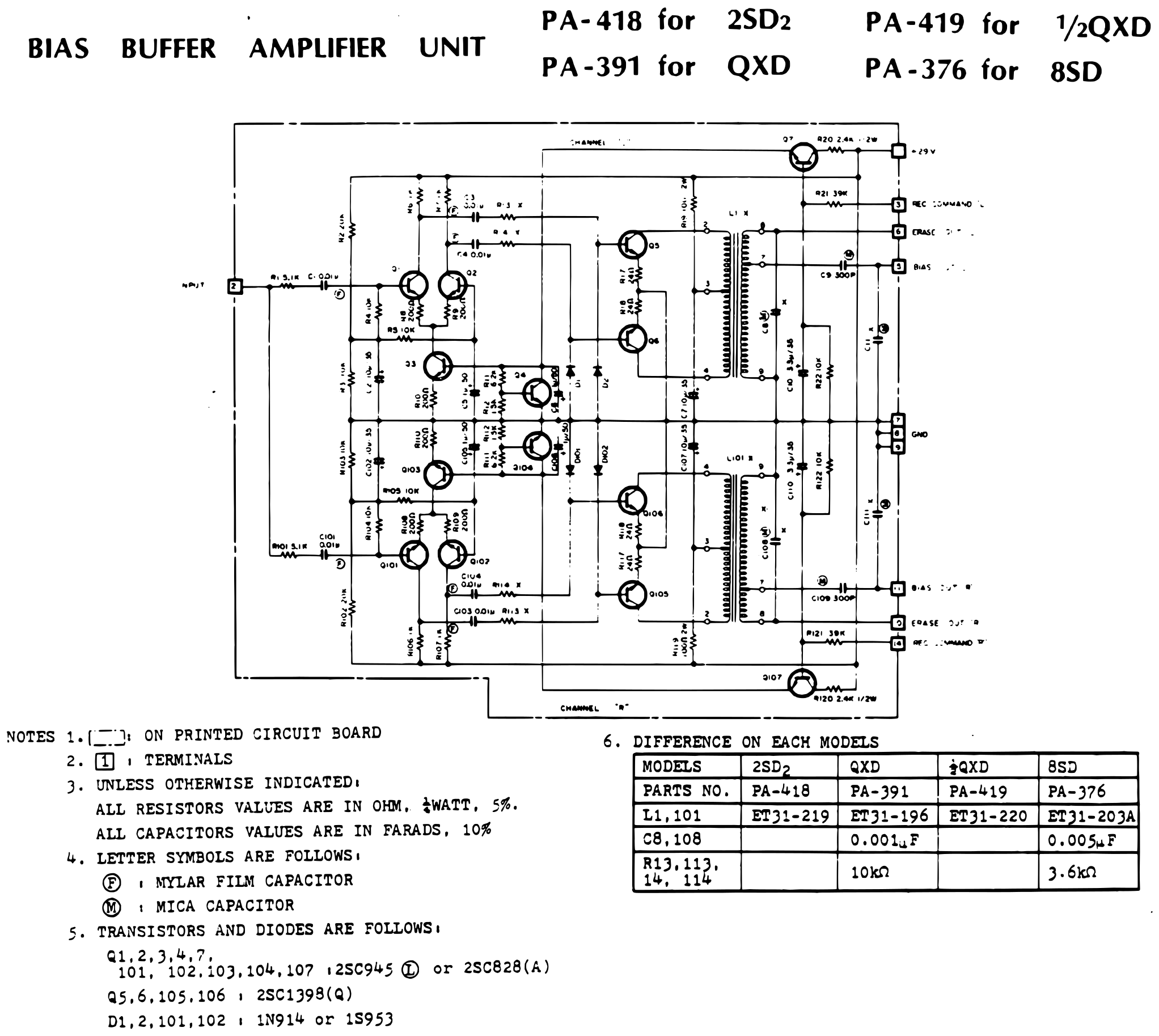 ⤢ zoomBIAS BUFFER AMPLIFIER UNIT: schematic of the two-channel bias buffer amplifier with its erase and bias outputs, and a table of the parts that differ between the 2SD₂, QXD, ½QXD and 8SD versions · Redrawn as vector — zooms cleanly ·
Download the traced vector PDF
BIAS BUFFER AMPLIFIER P.C.B. Ass'y (PM-822A)↑ TOP
Component layout of the bias buffer amplifier board, printed board PM-822A, shared by all four versions, with the R and L channels side by side and their transformers L101 and L1 at the bottom.
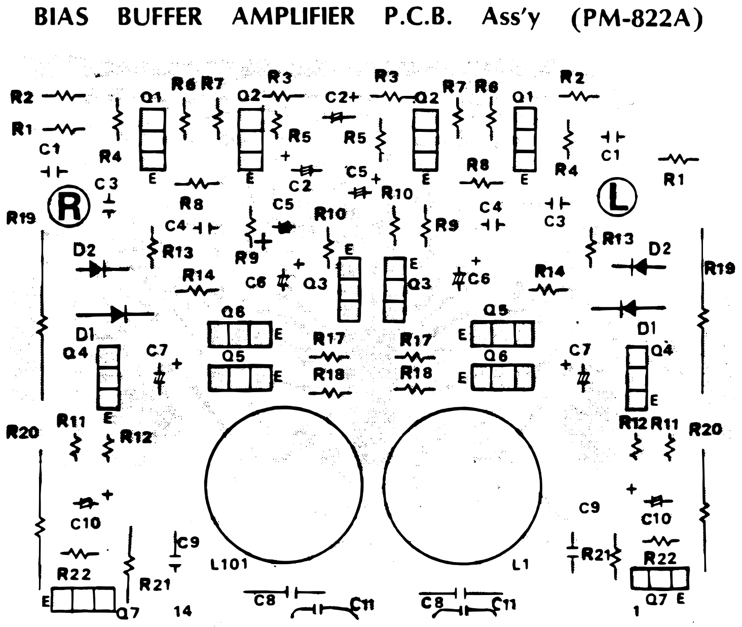 ⤢ zoomBIAS BUFFER AMPLIFIER P.C.B. Ass'y (PM-822A): component layout of the bias buffer amplifier board · Redrawn as vector — zooms cleanly ·
Download the traced vector PDF
VR P.C.B. Assy PA-373 (PM-873)↑ TOP
Component layout of the VR board PA-373, printed board PM-873, carrying the eight calibration pots VR1 to VR8 and connector CN13F. The sheet refers to the record reproduce electronics wiring diagram for its connections.
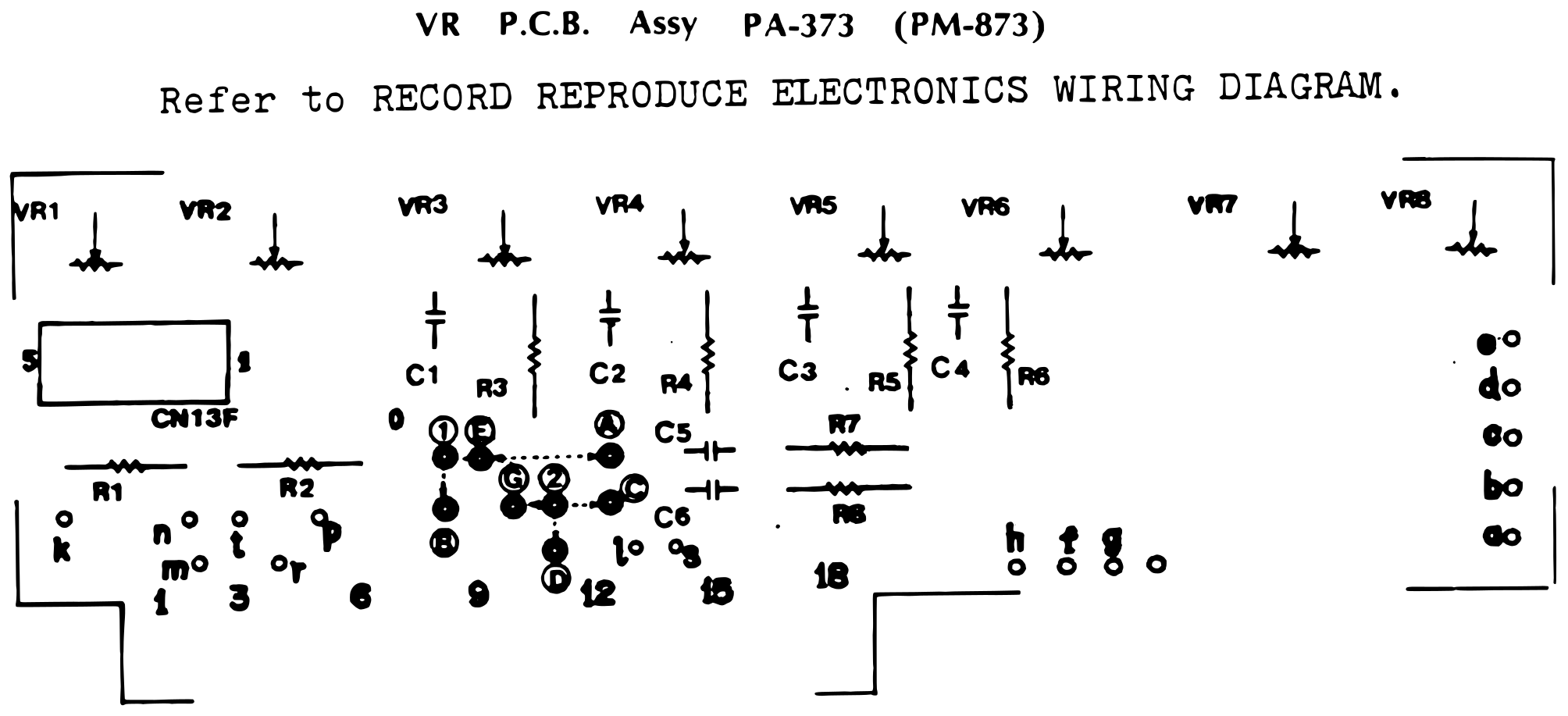 ⤢ zoomVR P.C.B. Assy PA-373 (PM-873): component layout of the VR board with pots VR1 to VR8 · Redrawn as vector — zooms cleanly ·
Download the traced vector PDF
VU P.C.B. Ass'y PA-401 (PM-901)↑ TOP
Foil pattern of the VU board PA-401, printed board PM-901, with the R and L sides marked. The sheet refers to the record reproduce electronics wiring diagram.
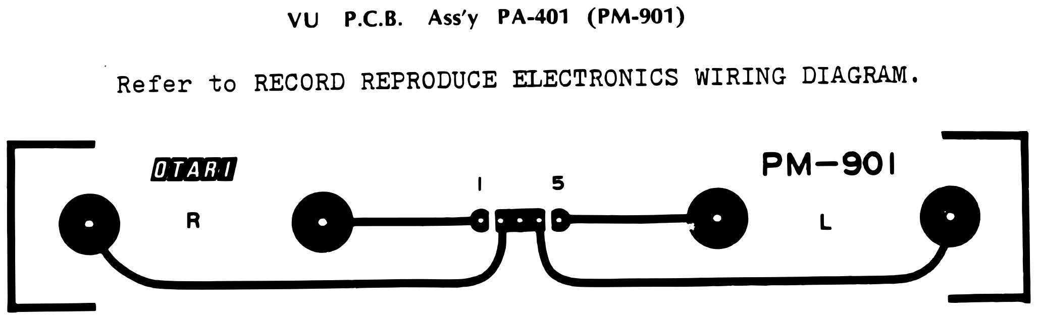 ⤢ zoomVU P.C.B. Ass'y PA-401 (PM-901): foil pattern of the VU board · Redrawn as vector — zooms cleanly ·
Download the traced vector PDF
SWITCH P.C.B. Ⓐ Ass'y PA-304 (PM-812)↑ TOP
Layout of switch board A, PA-304, printed board PM-812, with switches SW1 to SW3 and lettered connection points. The sheet refers to the record reproduce electronics wiring diagram.
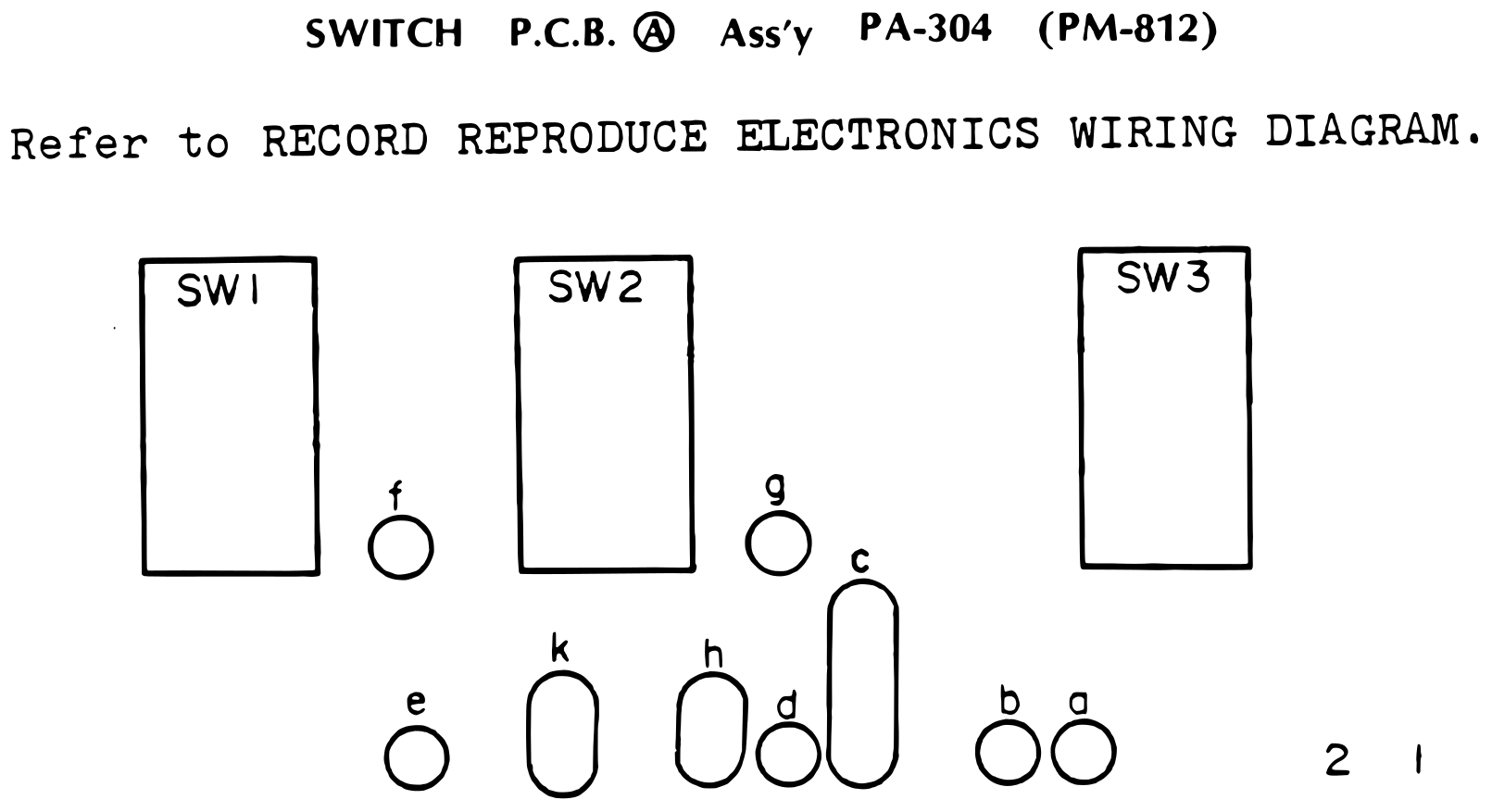 ⤢ zoomSWITCH P.C.B. Ⓐ Ass'y PA-304 (PM-812): layout of switch board A with switches SW1 to SW3 · Redrawn as vector — zooms cleanly ·
Download the traced vector PDF
AMPLIFIER MOTHER P.C.B. Ass'y PA-345 (PM-817A)↑ TOP
Layout of the amplifier mother board PA-345, printed board PM-817A, drawn sideways: the edge connectors for the reproduce, sel-rep, test oscillator, record and bias boards, the relays, and the connectors to the switch boards, the VR board and the deck. The sheet refers to the record reproduce electronics wiring diagram.
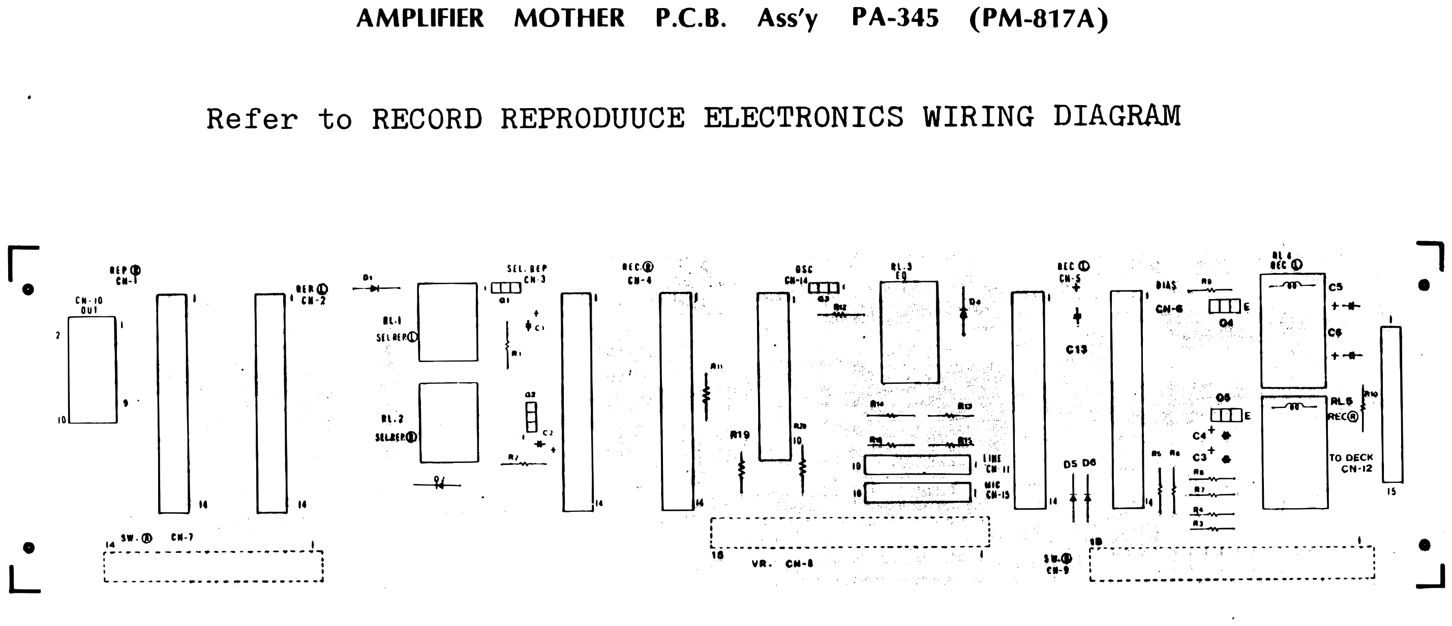 ⤢ zoomAMPLIFIER MOTHER P.C.B. Ass'y PA-345 (PM-817A): layout of the amplifier mother board with its plug-in board connectors and relays · Redrawn as vector — zooms cleanly ·
Download the traced vector PDF
CONTROL UNIT (PA-316)↑ TOP
The transport control board (PA-316): TTL logic that takes the STOP, RWD, F FWD, PLAY, EDIT, REC, MOTION SENSING and QUICK START inputs and drives transistor outputs for rewind, fast forward, play, record and the supply and take-up brakes. The notes list the IC, transistor and diode types.
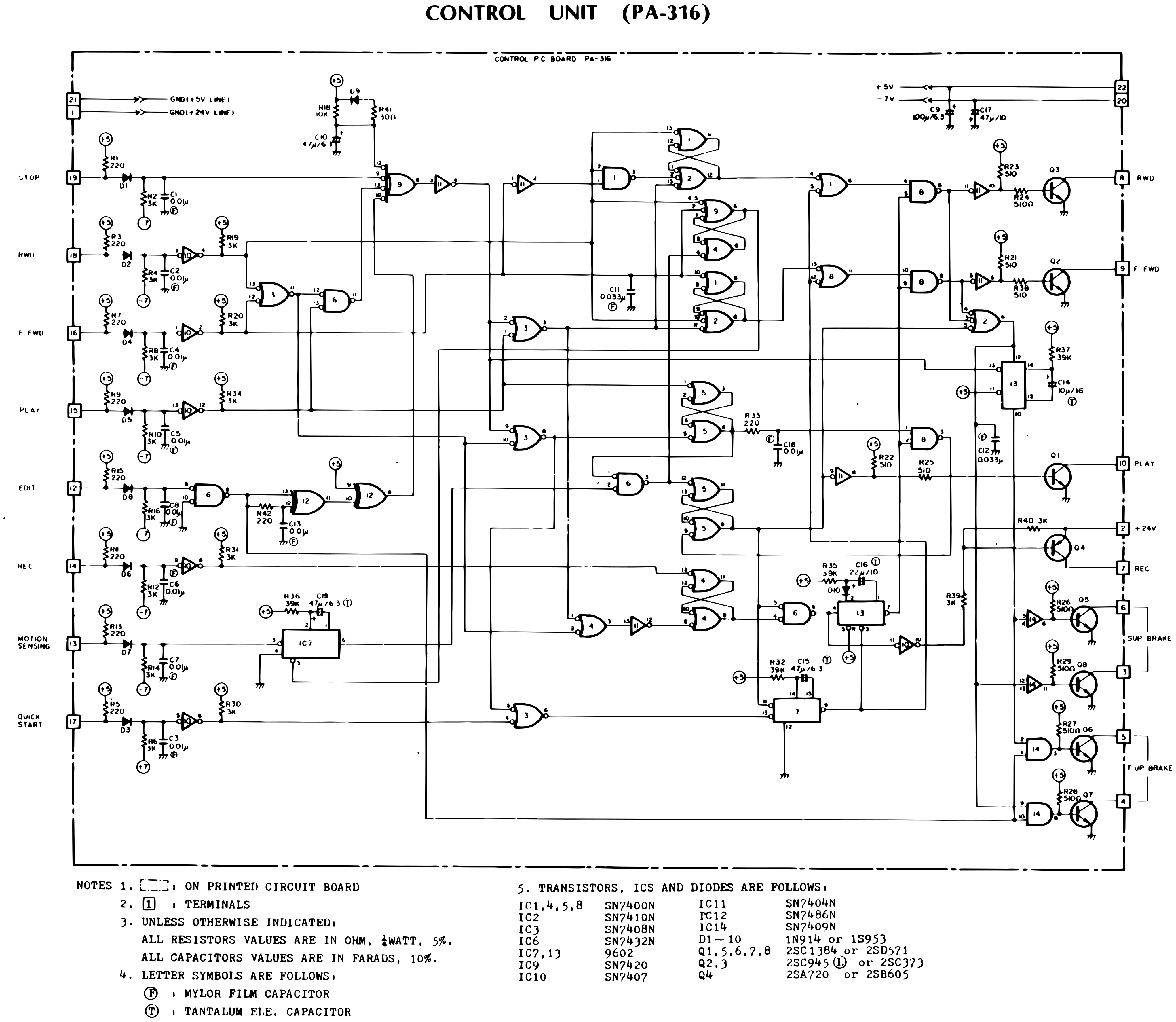 ⤢ zoomCONTROL UNIT (PA-316): schematic of the TTL transport control logic, from the function inputs to the transistor drivers for the transport functions and brakes · Redrawn as vector — zooms cleanly ·
Download the traced vector PDF
CONTROL P.C.B. Ass'y PA-316 (PM-825A)↑ TOP
Component layout of the control board PA-316, printed board PM-825A, with integrated circuits IC1 to IC14 in two rows.
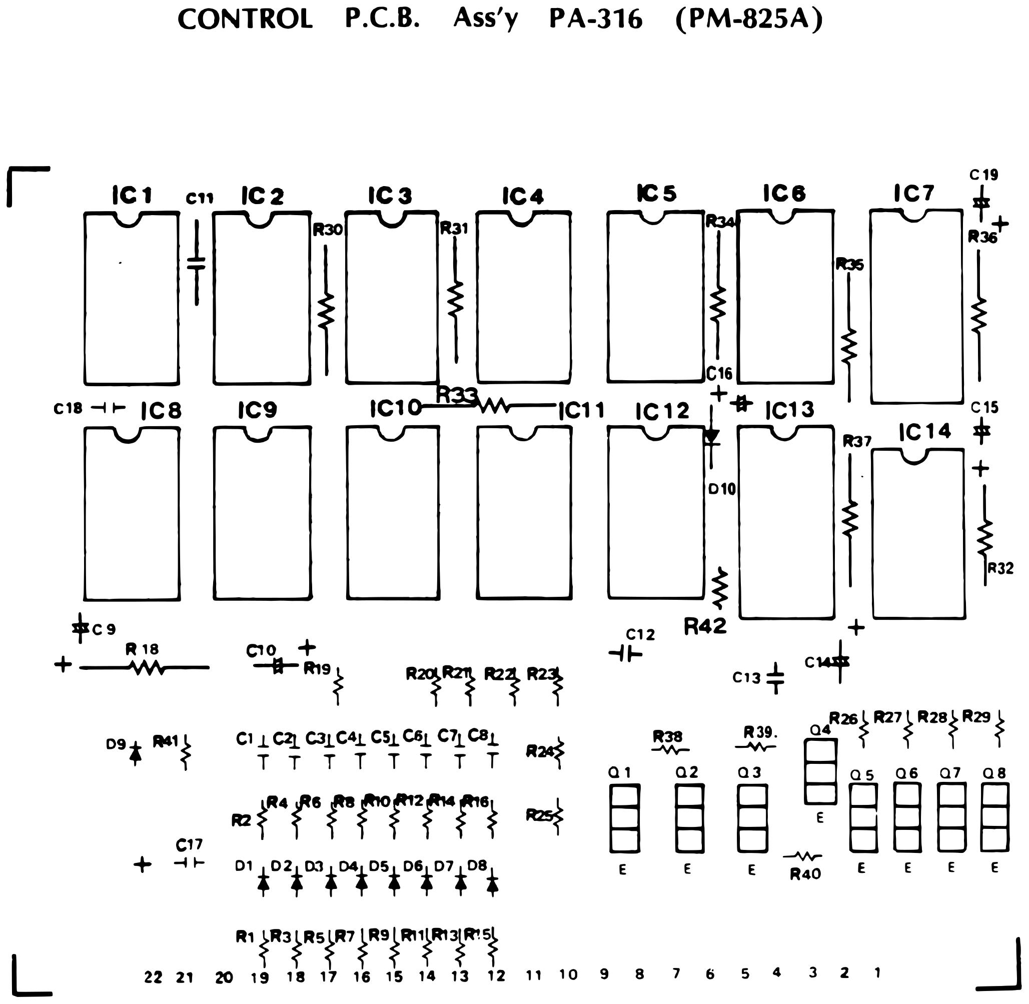 ⤢ zoomCONTROL P.C.B. Ass'y PA-316 (PM-825A): component layout of the control board with IC1 to IC14 · Redrawn as vector — zooms cleanly ·
Download the traced vector PDF
MASTER OSCILLATOR AND POWER SUPPLY UNIT (PA-315)↑ TOP
The master oscillator and power supply board (PA-315): the transistor oscillator that produces the bias output, and the rectifiers and filters for the +10.5 V, +34 V, +36 V, regulated +30 V and −7 V supplies. The notes list the transistor types and that C20 and C21 are used on the 8SD only.
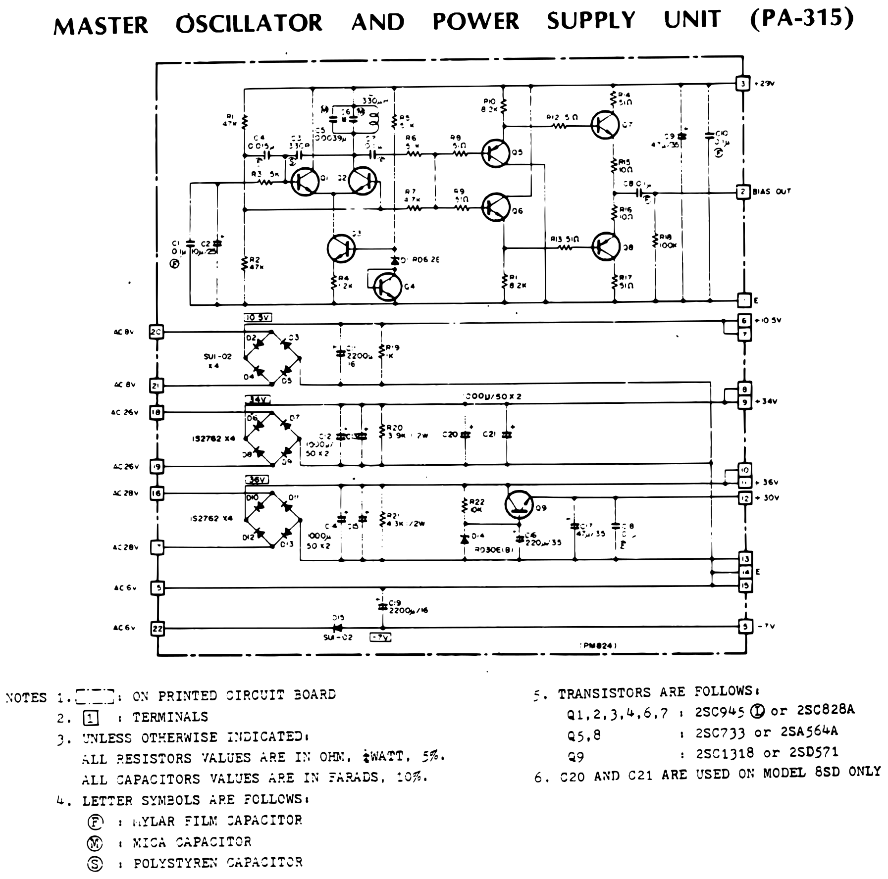 ⤢ zoomMASTER OSCILLATOR AND POWER SUPPLY UNIT (PA-315): schematic of the master oscillator and the rectified and regulated supplies · Redrawn as vector — zooms cleanly ·
Download the traced vector PDF
MASTER OSCILLATOR AND POWER SUPPLY P.C.B. Ass'y PA-315 (PM-824)↑ TOP
Component layout of the master oscillator and power supply board PA-315, printed board PM-824, with the rectifier diodes along the left and the filter capacitors in the middle.
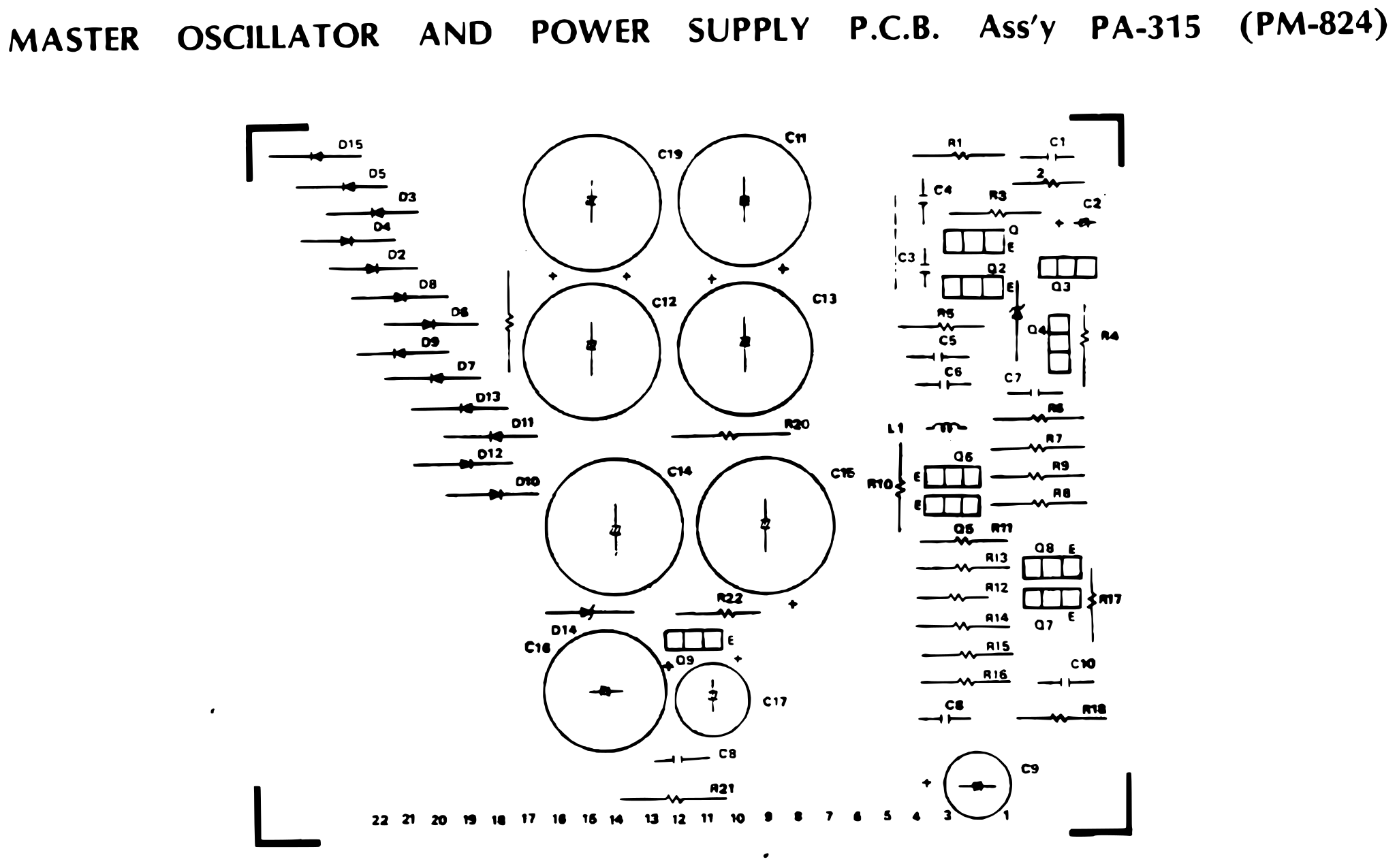 ⤢ zoomMASTER OSCILLATOR AND POWER SUPPLY P.C.B. Ass'y PA-315 (PM-824): component layout of the master oscillator and power supply board · Redrawn as vector — zooms cleanly ·
Download the traced vector PDF
MX-5050 2S D₂ HEAD ASSEMBLY (PA-387)↑ TOP
Head wiring for the 2SD₂: the two-channel record/erase head and the reproduce head wired through the head board PA-387, with the 100 Ω resistors R1 to R4 and the reproduce head selecting switch SW1 for 2-track and 4-track playback.
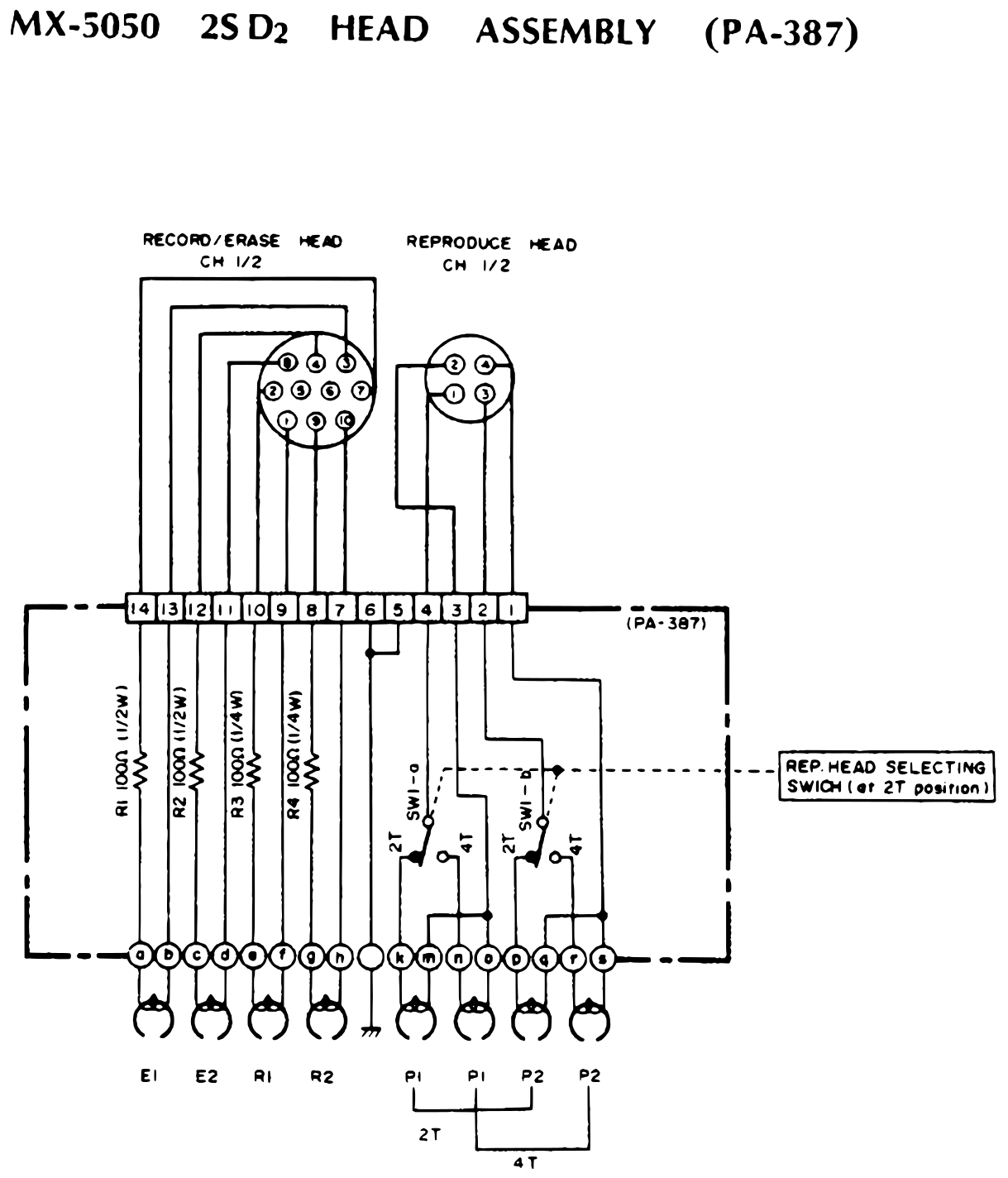 ⤢ zoomMX-5050 2S D₂ HEAD ASSEMBLY (PA-387): wiring of the record/erase and reproduce heads through the head board, with the 2T/4T reproduce head selecting switch · Redrawn as vector — zooms cleanly ·
Download the traced vector PDF
MX-5050 2SD₂ HEAD P. C. B. Ass'y PA-387 (PM-887)↑ TOP
Layout of the 2SD₂ head board PA-387, printed board PM-887, with resistors R1 to R4 and switch SW1.
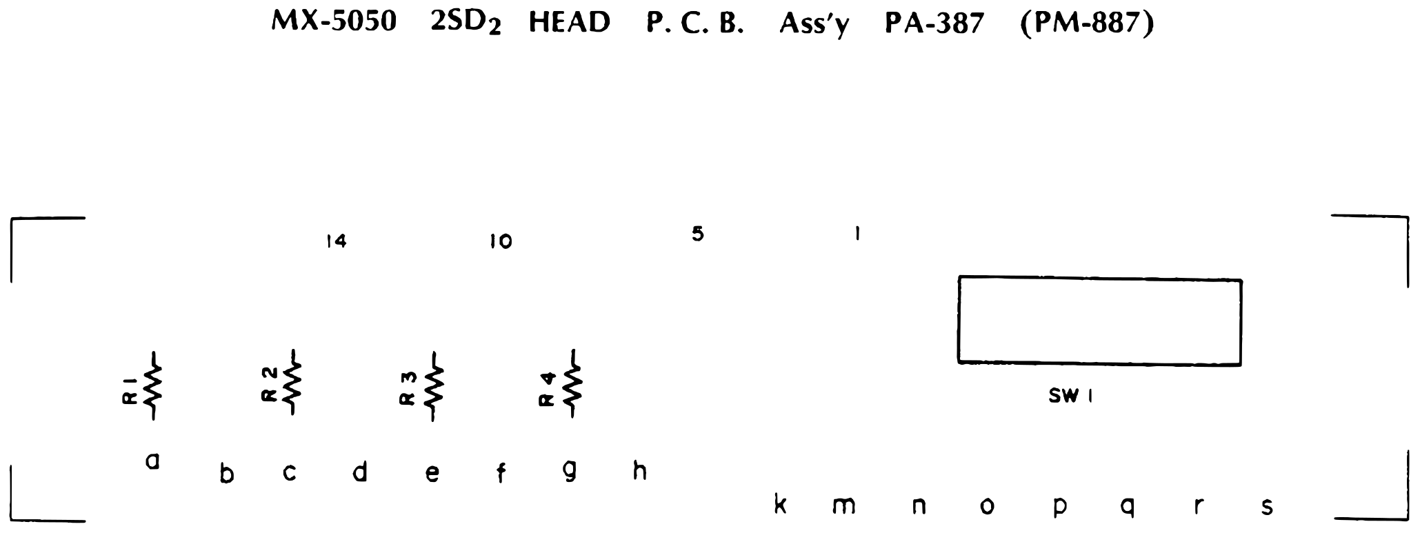 ⤢ zoomMX-5050 2SD₂ HEAD P. C. B. Ass'y PA-387 (PM-887): layout of the 2SD₂ head board · Redrawn as vector — zooms cleanly ·
Download the traced vector PDF
MX-5050 ½QXD, QXD HEAD ASSEMBLY (PA-386)↑ TOP
Head wiring for the ½QXD and QXD: the record/erase heads for channels 1/3 and 2/4 and the matching reproduce heads, wired through the head board PA-386 with resistors R1 to R8.
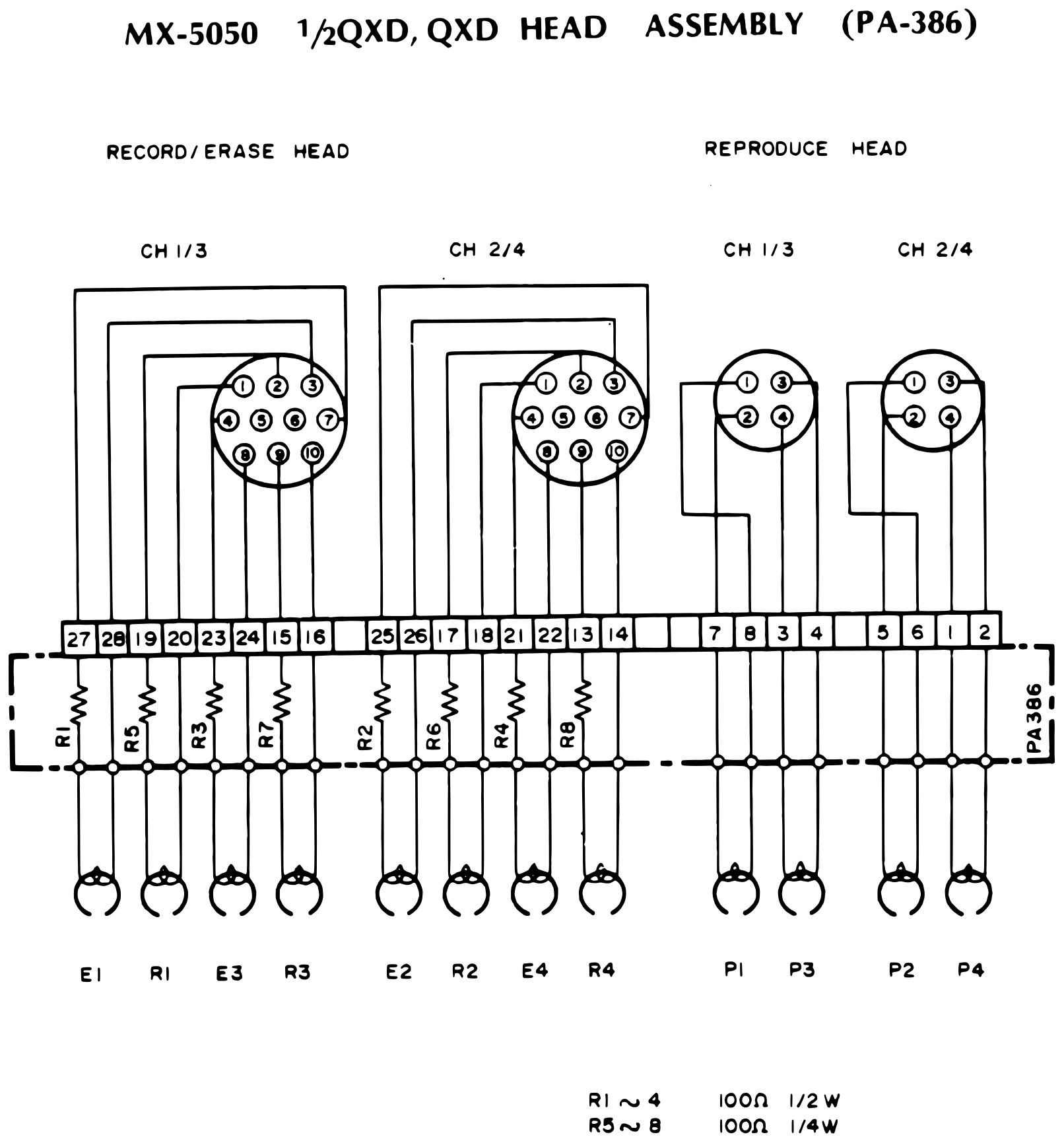 ⤢ zoomMX-5050 ½QXD, QXD HEAD ASSEMBLY (PA-386): wiring of the four-channel record/erase and reproduce heads through the head board · Redrawn as vector — zooms cleanly ·
Download the traced vector PDF
MX-5050 QXD HEAD P. C. B. Ass'y PA-386 (PM-886)↑ TOP
Layout of the QXD head board PA-386, printed board PM-886, with resistors R1 to R8.
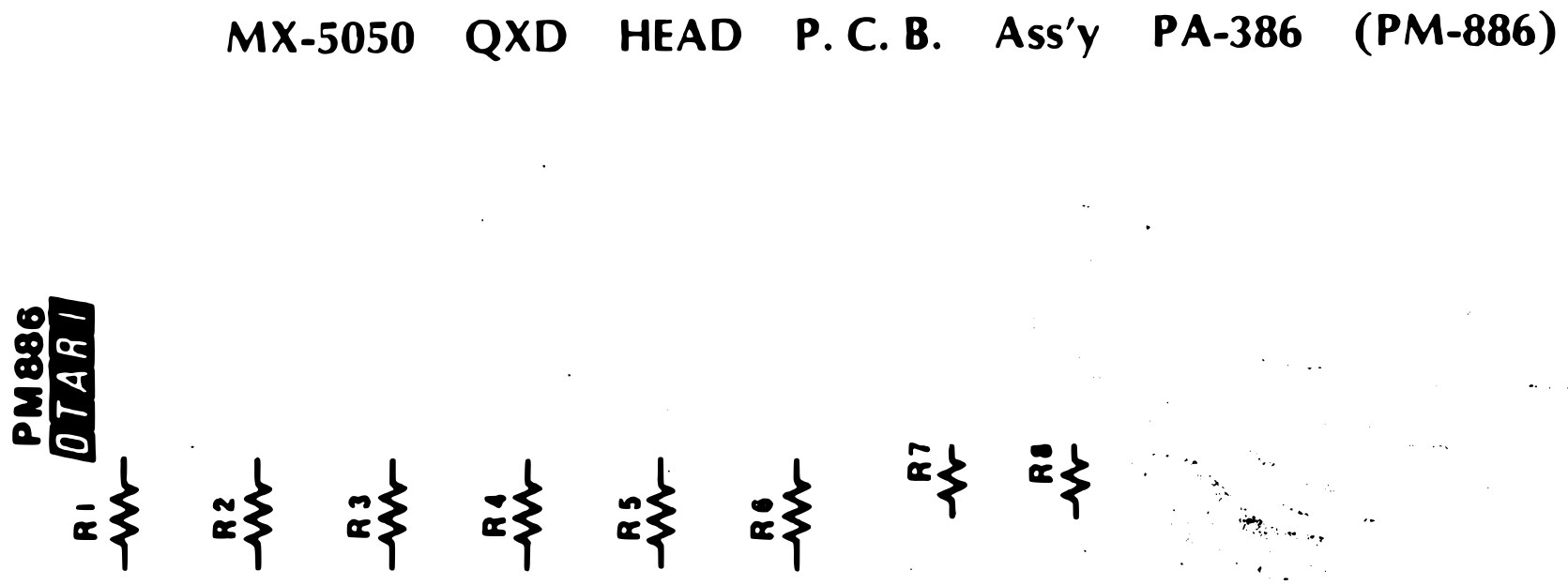 ⤢ zoomMX-5050 QXD HEAD P. C. B. Ass'y PA-386 (PM-886): layout of the QXD head board · Redrawn as vector — zooms cleanly ·
Download the traced vector PDF
MX-5050 8SD HEAD ASSEMBLY↑ TOP
Head wiring for the 8SD: the record/erase heads for channels 1/2, 3/4, 5/6 and 7/8 wired to connector CN202, and the four reproduce heads wired to CN201, with the wire colour of each lead.
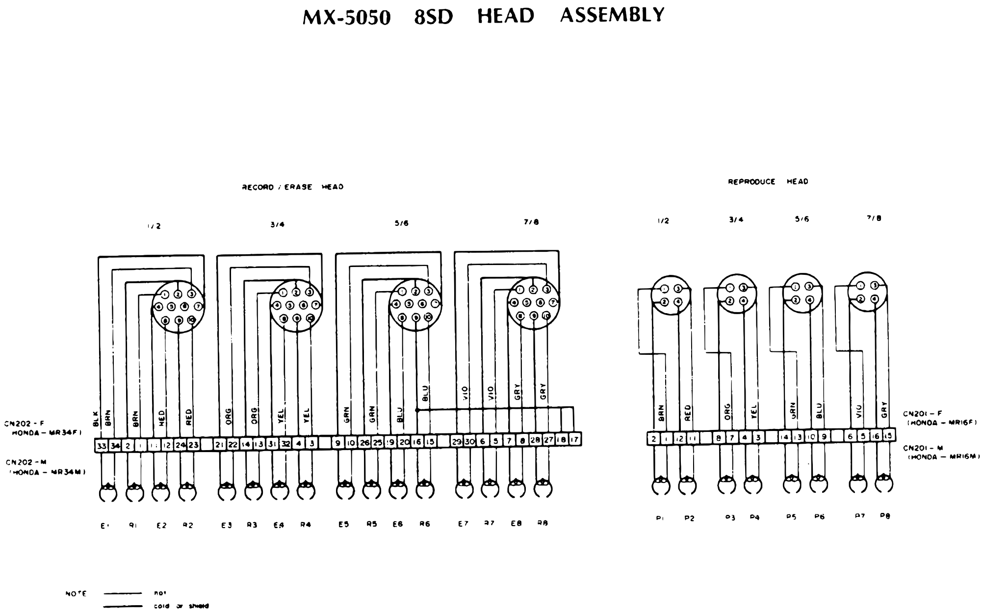 ⤢ zoomMX-5050 8SD HEAD ASSEMBLY: wiring of the eight-channel record/erase and reproduce heads to connectors CN202 and CN201, with wire colours · Redrawn as vector — zooms cleanly ·
Download the traced vector PDF
CAPSTAN SERVO MOTER POWER SUPPLY P.C.B. PA-377 (PM-875A)↑ TOP
Component layout of the capstan servo motor power supply board PA-377, printed board PM-875A, with relays RL1 and RL2 and regulator IC1. The sheet refers to the tape transport electronics wiring diagram.
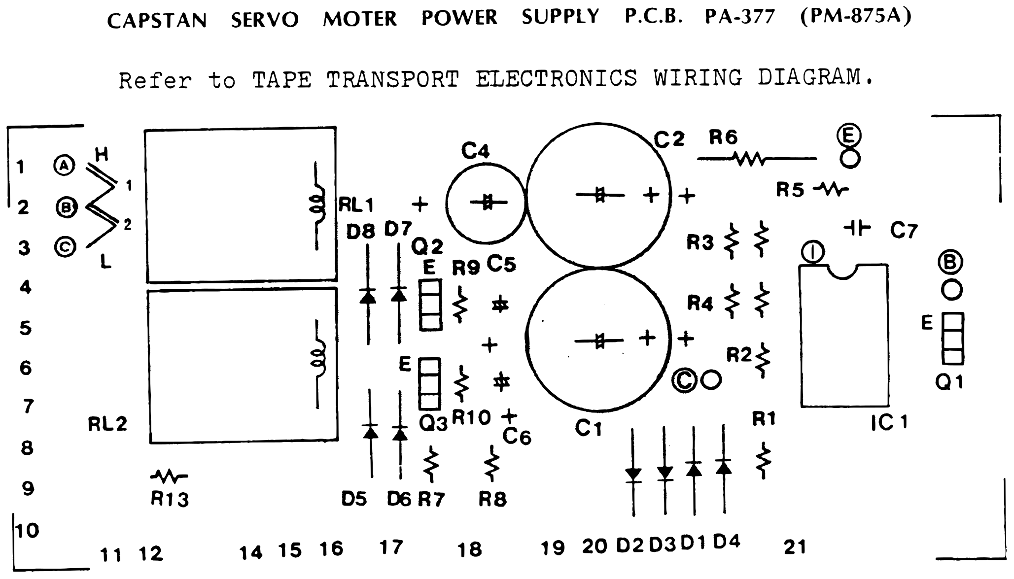 ⤢ zoomCAPSTAN SERVO MOTER POWER SUPPLY P.C.B. PA-377 (PM-875A): component layout of the capstan servo motor power supply board · Redrawn as vector — zooms cleanly ·
Download the traced vector PDF
POWER SWITCH P.C.B. Ass'y PA-378 (PM-833A)↑ TOP
Layout of the power switch board PA-378, printed board PM-833A, with the EDIT, REEL, SPEED and POWER switches and lettered connection points. The sheet refers to the tape transport electronics wiring diagram.
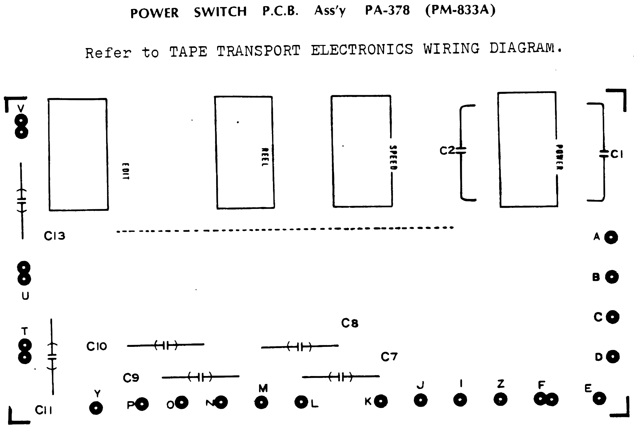 ⤢ zoomPOWER SWITCH P.C.B. Ass'y PA-378 (PM-833A): layout of the power switch board with the EDIT, REEL, SPEED and POWER switches · Redrawn as vector — zooms cleanly ·
Download the traced vector PDF
TRANSPORT MOTHER P.C.B. Ass'y PA-314 (PM-823A)↑ TOP
Layout of the transport mother board PA-314, printed board PM-823A, with relays RL1 (RWD), RL2 (FFWD) and RL3 (PLAY) and numbered edge connections. The sheet refers to the tape transport electronics wiring diagram.
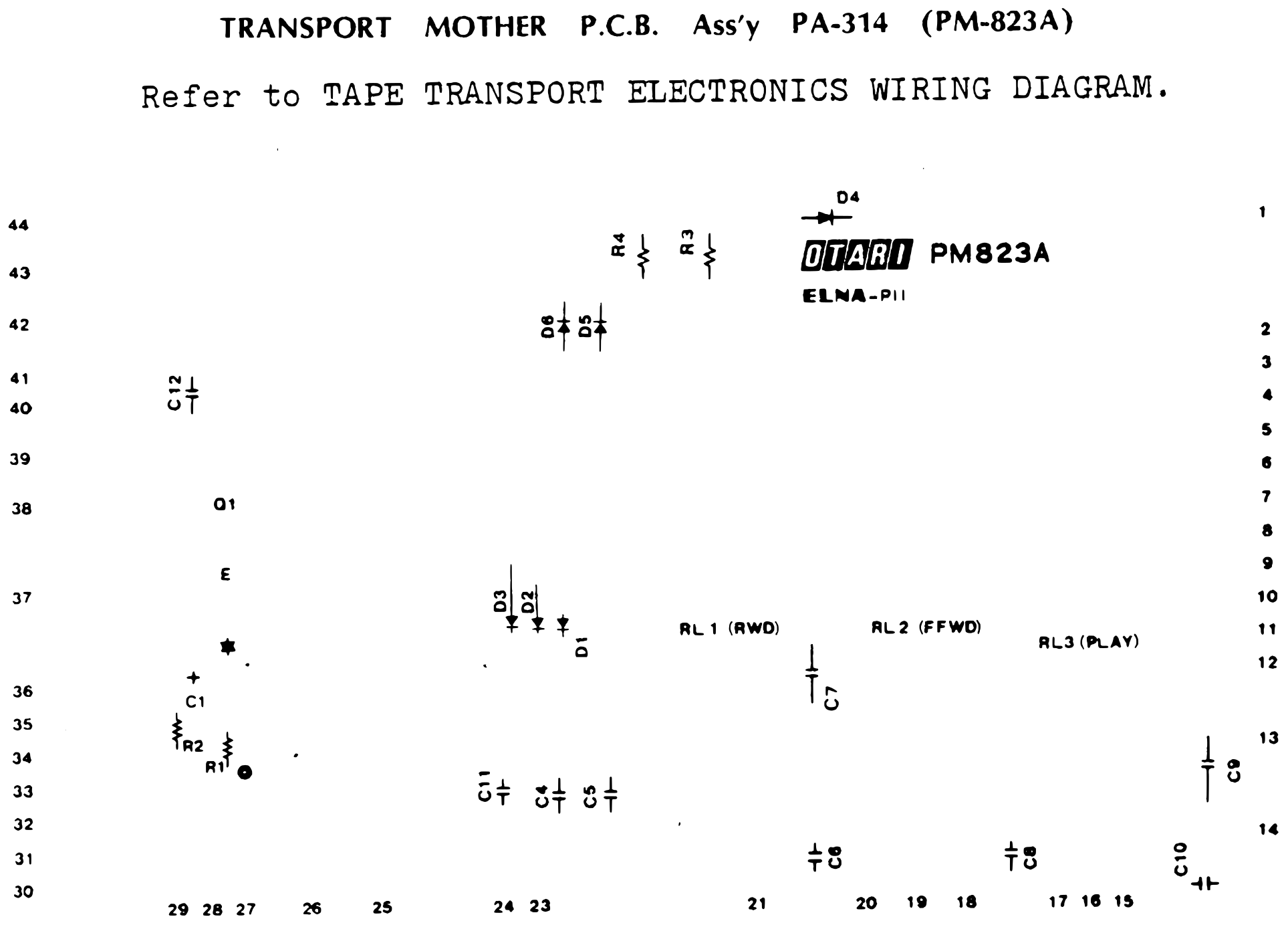 ⤢ zoomTRANSPORT MOTHER P.C.B. Ass'y PA-314 (PM-823A): layout of the transport mother board with the RWD, FFWD and PLAY relays · Redrawn as vector — zooms cleanly ·
Download the traced vector PDF
MX-5050 2SD₂,QXD, ½QXD,8SD RECORD REPRODUCE ELECTTRONICS (AF-237) WIRING DIAGRAM↑ TOP
Interconnect wiring for the record/reproduce electronics: the amplifier mother board (PA-345) with the reproduce (PA-372), sel-rep (PA-375), test oscillator (PA-379), record (PA-371) and bias buffer boards plugged into it, wired to switch boards A and B (PA-304, PA-305), the VU board (PA-401) and the VR board (PA-373), and out to the line, microphone, headphone, noise-reduction remote, deck and head connectors. This sheet prints the board number in full, (AF-237).
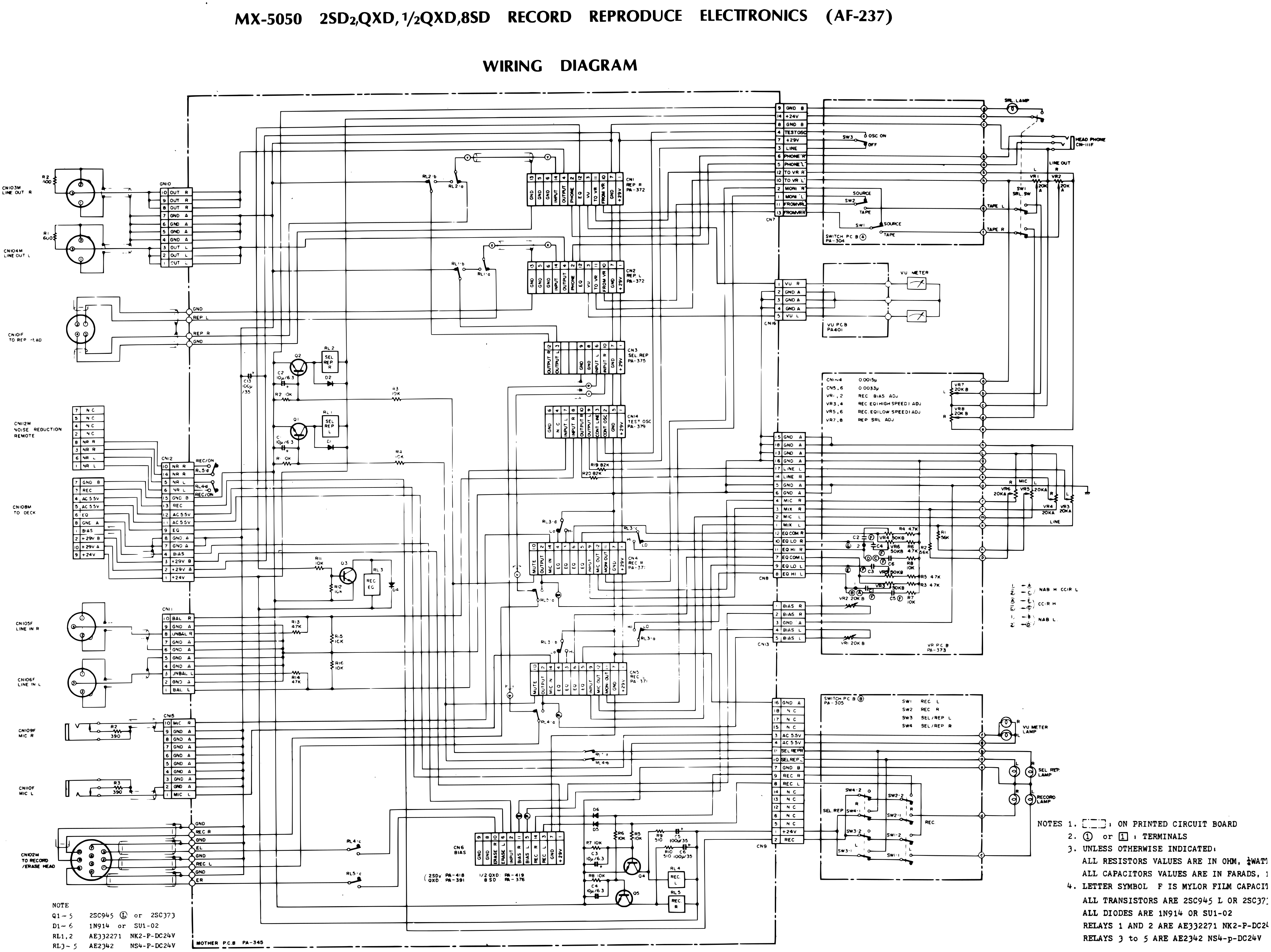 ⤢ zoomMX-5050 2SD₂,QXD, ½QXD,8SD RECORD REPRODUCE ELECTTRONICS (AF-237) WIRING DIAGRAM: the amplifier mother board and its plug-in boards wired to the switch, VU and VR boards and the input, output and head connectors · Redrawn as vector — zooms cleanly ·
Download the traced vector PDF
MX-5050 2SD₂,QXD, ½QXD,8SD TAPE TRANSPORT ELECTRONICS (TD-5250D) WIRING DIAGRAM↑ TOP
Interconnect wiring for the tape transport electronics: the 8SD and QXD head assemblies, the capstan motor and its power supply board (PA-377), the take-up and supply motors, the power transformer, the power switch board (PA-378), the transport mother board (PA-314) with the control board (PA-316) and the master oscillator and power supply board (PA-315), and the remote control unit (CR-705A).
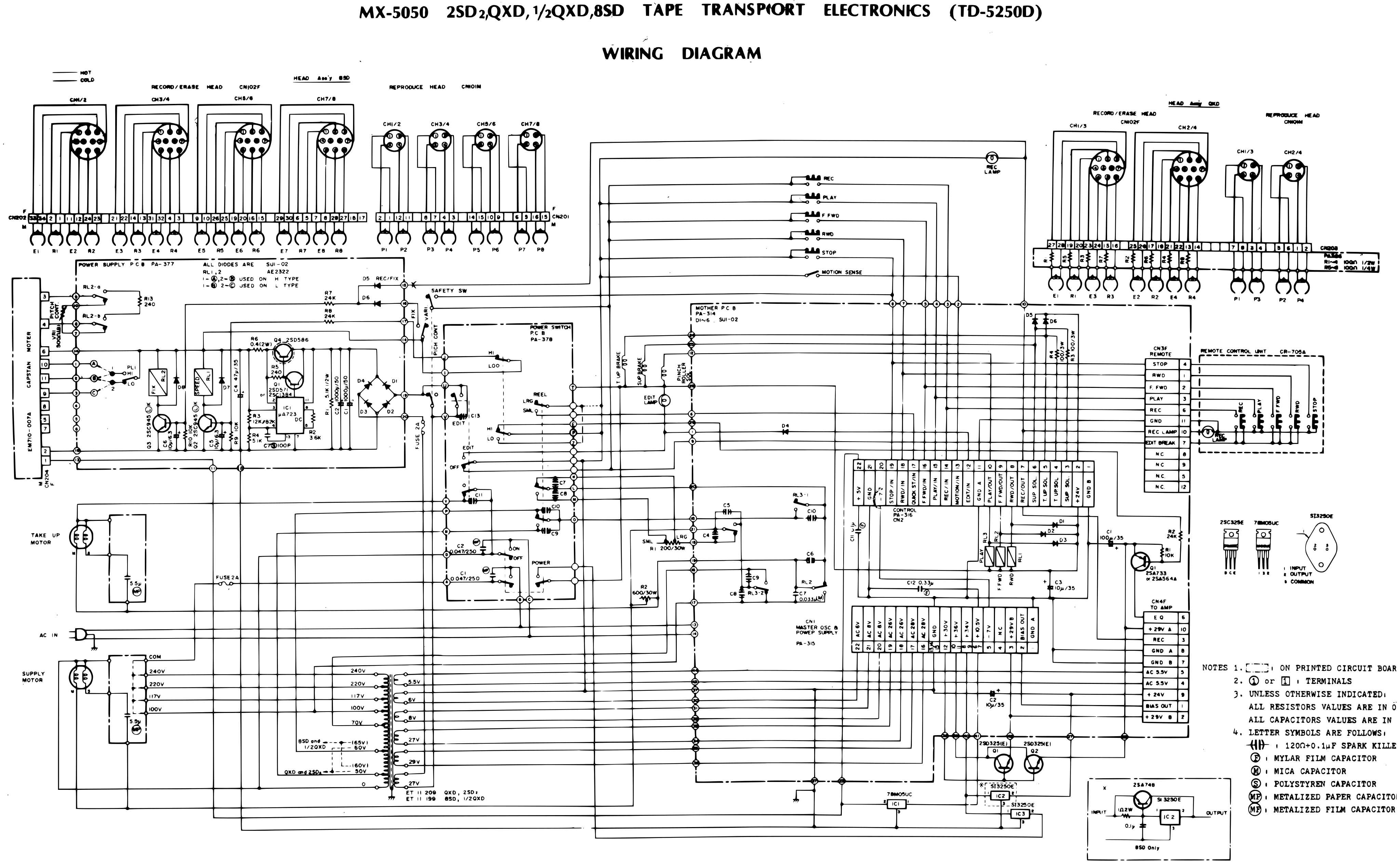 ⤢ zoomMX-5050 2SD₂,QXD, ½QXD,8SD TAPE TRANSPORT ELECTRONICS (TD-5250D) WIRING DIAGRAM: head assemblies, motors, power transformer and transport boards wired together, with the remote control unit · Redrawn as vector — zooms cleanly ·