Maintenance manual · Front matter · scan pages 1-7
Front Matter
OTARI®
MX-5050 PROFESSIONAL RECORDER
MODELS MX-5050 2S, 4S, 2SD AND 4SD
MAINTENANCE MANUAL
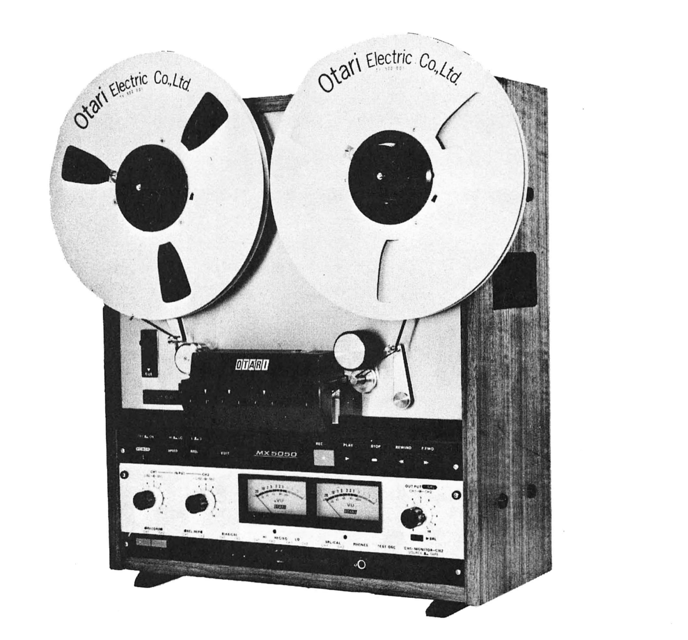 ⤢ zoomMX-5050 recorder loaded with two Otari Electric Co., Ltd. reels
MX-5050 SERIES PROFESSIONAL RECORDER — INTRODUCTION↑ TOP
This manual supplement provides detailed maintenance information, schematics, and parts lists for the Otari MX-5050 Series Models 2S, 4S, 2SD and 4SD Professional Recorder. For descriptive information, installation and operating instructions, preventive maintenance and routine adjustment procedures, refer to Otari Instruction Manual Catalog No. OIM-1005E.
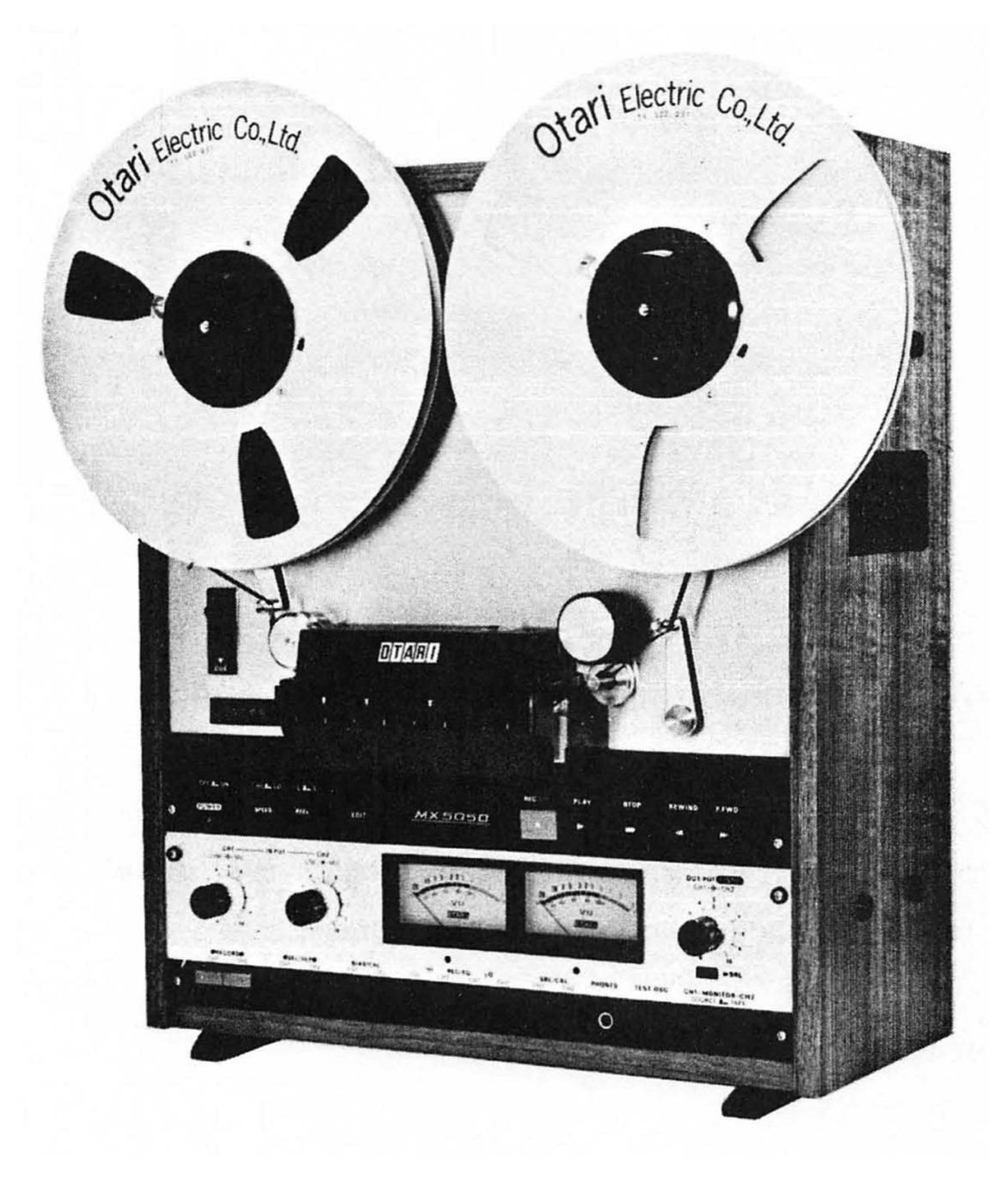 ⤢ zoomMX-5050 2SD Recorder
COMMUNICATION WITH OTARI — FOR SERVICE INFORMATION AND PARTS↑ TOP
The OTARI PRODUCTS are manufactured under strict quality control and each unit was carefully tested and inspected prior to shipment from our factory.
If, however, some adjustments or technical support become necessary, replacement parts are required, or technical questions arise, please contact your nearest Otari dealer or write to:
| OTARI ELECTRIC CO., LTD. | OTARI CORPORATION |
|---|---|
| 4-29-18, Minami Ogikubo, | 1559 Industrial Road, San Carlos, |
| Suginamiku, Tokyo, 167, Japan | California 94070, U. S. A. |
| Phone: (03) 333 - 9631 | Phone: (415) 592 - 8311 |
| Telex No.: OTRDENKI J26604 | Telex No.: TWX 910-376-4890 |
Another part of Otari continuous technical support program for our products, is the continuous revision of manuals as the equipment is improved or modified.
In order for you to receive our information and service applicable to your requirement, and for the technical support to function properly, please include the following information, most of which can be obtained from the name plate on the equipment.
- Model Number
- Serial Number
- Date of purchase
- Name and address of dealer from whom machine was purchased.
- Power requirements (voltage and frequency)
- Manual number which you are referring
TABLE OF CONTENTS↑ TOP
- 1 GENERAL INFORMATION
- 2 TAPE TRANSPORT MAINTENANCE
- 3 PERFORMANCE TESTS AND ELECTRONIC ALIGNMENT
- 4 MAJOR COMPONENT REPLACEMENT PROCEDURES
- 5 TROUBLESHOOTING
- 6 PARTS LISTS AND SCHEMATICS
List of Illustrations↑ TOP
| Figure | Title | Page |
|---|---|---|
| 1-1 | Lifting Head Cover | 1-2-(1) |
| 1-2 | Demagnetizing | 1-2-(2) |
| 1-3 | Lubrication | 1-2-(3) |
| 2-1 | Transport Access | 2-1 |
| 2-2 | Measurement | 2-2 |
| 2-3 | Adjusting Parts Location | 2-2 |
| 2-4 | Tape Tension Adjustment Resistors | 2-3 |
| 2-5 | Measurement | 2-4 |
| 2-6 | Adjusting Parts Location | 2-4 |
| 2-7 | Adjusting Parts Location | 2-5 |
| 3-1 | ASA "A" Weighted Filter | 3-4-(1) |
| 3-2 | Using Test Tape | 3-4-(5) |
| 3-3 | Access to Electronic Assembly | 3-5 |
| 3-4 | Adjusting Parts Location | 3-5, 3-6 |
| 3-5 | Bias Buffer Adjusting Parts | 3-6-(4) |
| 4-1 | Reel Table and Motor | 4-1-(1) |
| 4-2 | Capstan Motor Location (2S or 4S) | 4-1-(4) |
| 4-3 | Capstan Motor Location (2S or 4SD) | 4-1-(4) |
| 4-4 | Brake Assembly Location | 4-1-(5) |
| 4-5 | Pinch Roller Removal | 4-1-(6) |
| 4-6 | Top View of Head Assembly | 4-2-(1) |
| 4-7 | Front View of Head Assembly | 4-2-(1) |
| 4-8 | Bottom View of Head Assembly | 4-2-(1) |
| 4-9 | Head Alignment | 4-2-(1) |
| 4-10 | Input Circuity | 4-3-(1) |
| 4-11 | Input Transformer Installation | 4-3-(1) |
| 4-12 | Input Transformer Wiring | 4-3-(1) |
| 4-13 | Output Circuitry | 4-3-(2) |
| 4-14 | Output Transformer Installation | 4-3-(2) |
| 4-15 | Output Transformer Wiring | 4-3-(2) |
List of Table↑ TOP
| Table | Title | Page |
|---|---|---|
| 1-1 | Test and Maintenance Equipment | 1-1 |
| 1-2 | Alignment Test Tapes | 1-1 |
| 2-1 | Tension Specifications | 2-2 |
| 2-2 | Tape Tesnion Specifications | 2-3 |
| 3-1 | Signal-to-noise Specifications (ASA weighted) | 3-4-(1) |
| 3-2 | Crosstalk Specifications (Between Adjacent Channels) | 3-4-(3) |
| 3-3 | Flutter and Wow Specification | 3-4-(6) |
| 5-1 | Troubleshooting Hints | 5-2 |