MARK III/4 Instruction and Maintenance Manual — Digital Edition · Part 1 · scan pages 13-25
General Information
The MX-5050 MK Ⅲ-4 Recorder is a professional quality two-speed audio tape recorder/reproducer, designed for optimum performance and long life.
It accommodates a 1/2-inch wide tape and two 7 1/2 ips (19.05 cm/sec.) and 15 ips (38.1 cm/sec.) tape speeds.
1-1 SYSTEM DESCRIPTION↑ TOP
Among the many professional features of the MX-5050 MK Ⅲ-4 are: selective reproduction (SEL/REP), automatic motion sensing control by a proprietary microprocessor, an edit control that permits tape spilling, dynamic braking, an electronic tape timer, an adjustable cueing control for audible monitoring in fast forward and rewind, a dual frequency built-in test and cue-tone oscillator, adjustable record bias, equalization and level controls, XLR type connectors for input and output lines, separate line and microphone input level controls for each channel, a VU meter with a peak indicator for each channel, selecting switches for input and output levels, and a memory stop for automatically stopping the tape at a desired position except in record mode.
1-1-(1) TAPE TRANSPORT↑ TOP
All components of the tape transport system are mounted on a rigid aluminium base for stability.
The transport design incorporates two 6-pole induction motors for the tape reels and a dc servo motor (Direct drive) for the capstan.
A pitch control is available to adjust the control range of the tape speed within ±7% of the nominal speed for sound application.
The transport accommodates tape reels of 10 1/2 inches in NAB hub configurations.
In addition to the editing controls, a tape-splicing block (Figure 3-3) mounted on the head cover holds the tape for easy editing, cutting, and applying splicing tape.
Momentary contact pushbutton switches on the transport are used to select operational modes: record, play, stop, rewind, fast forward, and edit.
These modes except edit mode can be controlled from a remote location by using an optional remote control unit.
* Addenda * (MX-5050 BQ-2,MK-3-4,MK-3-8)↑ TOP
External Capstan Speed Control↑ TOP
For a special application such as interfacing with synchronizers or controllers,an external capstan speed control can be performed to connecting them to the "LOCATOR" connector located on the rear panel.
Capstan speed is controlled with the DC voltage (range:+-13V) which is fed to the "LOCATOR" connector PIN No.1 and No.2.
Capstan speed continuously varies in proportion to DC voltage;
At the -13V of DC voltage,capstan speed is minimum.
At the 0V of DC voltage,capstan speed is nominal. (15,7-1/2ips)
At the 13V (+8V on 15ips) of DC voltage,capstan speed is maximum.
To perform external capstan speed control,proceed as follows.
- Referring to SECTION 5-5 "FUSE REPLACEMENT of the manual,expose the Control P.C.B.
- Position two DIP switches on the Control P.C.B.,SW-2 and SW-3,to "NORMAL" and "EXT".
- Referring to the Table-2 "Pin Assignment",solder respective leads on connector,mated with the "LOCATOR" connector. Part No. of the mating connector : CN216203
- Connect the equipment to a synchronizer,or a controller.
Table-1 Control DC voltage and Capstan speed
| Nominal speed (ips) | Control DC voltage (V) | Capstan speed (%) |
|---|---|---|
| 15 | -13 | -60 |
| 15 | 0 | 0 |
| 15 | 8 # | +70 |
| 7-1/2 | -13 | -60 |
| 7-1/2 | 0 | 0 |
| 7-1/2 | 13 | +210 |
# On 15ips,Capstan speed is limited at the value of DC 8V.
(Ver.1.0)
Table-2 Pin assignment of the "LOCATOR" connector
| PIN No. | Description | Note |
|---|---|---|
| 1 # | GND,F | GND of EXT. CONT |
| 2 # | EXT.CONT | Capstan speed control DC voltage (range:+-13V) |
| 3 | CLOCK | Tach pulses (TTL logic convention) Frequency:40Hz at 15ips |
| 4 | DIR.(Rev/Fwd) | Transport Direction (TTL logic convention) |
| 5 | N.C. | |
| 6 | 15ips | Tape speed command (24V/open) |
| 7 | 7-1/2ips | |
| 8 | (3-3/4ips) | |
| 9 | N.C. | |
| 10 | RECORD | Transport control (TTL logic convention :active "LOW") |
| 11 | F.FWD | |
| 12 | RWD | |
| 13 | PLAY | |
| 14 | STOP | |
| 15 | N.C. | |
| 16 | 5V | Maximum load:50mA |
# On PIN No.1 and 2,a single-conductor shielded cable should be used.
(Ver.1.0)
TAPE SPEED ADJUSTMENT↑ TOP
# Replace the SECTION 6 "TAPE SPEED ADJUSTMENT" of the manual.
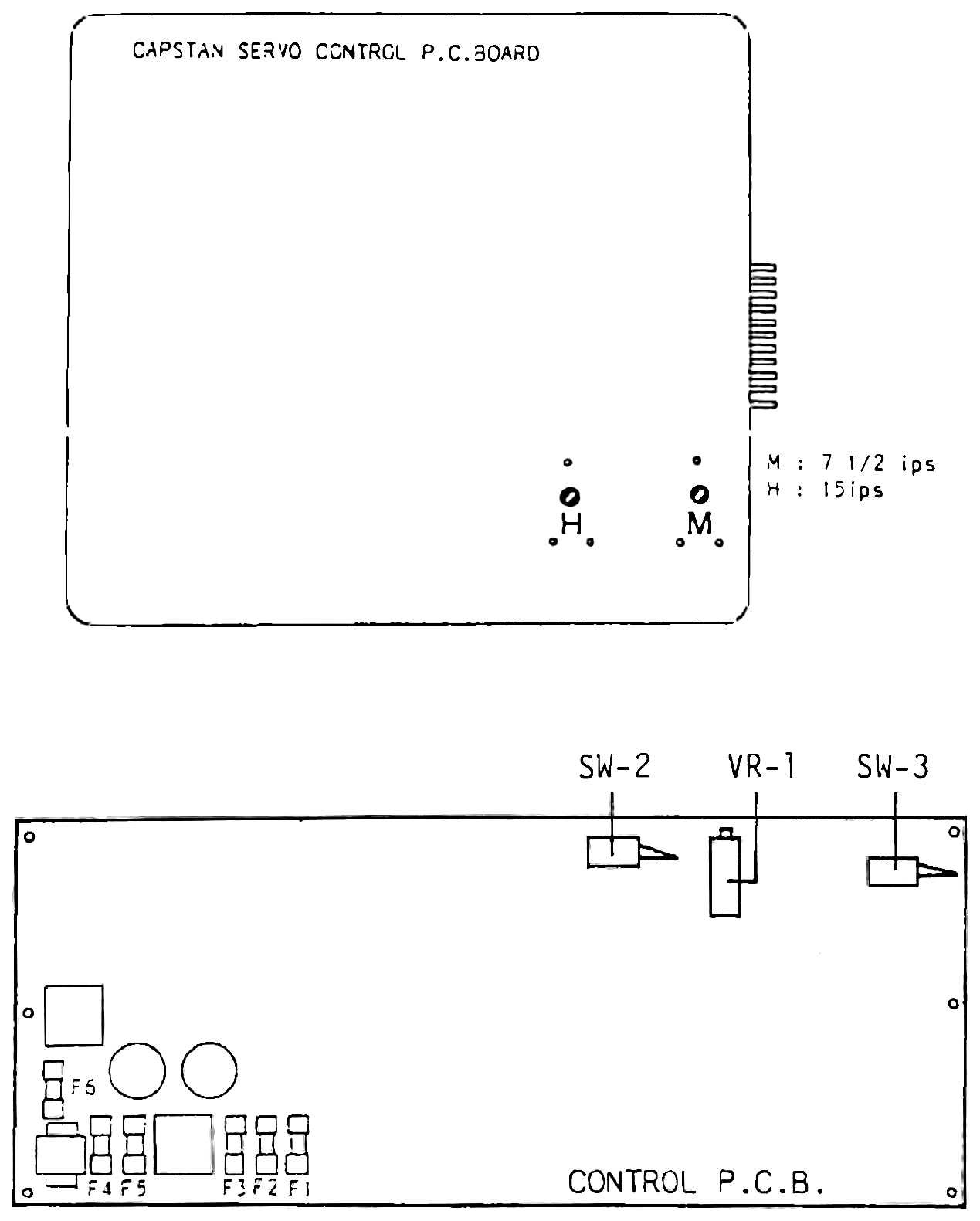
The tape speed can be adjusted by turning the speed adjustment pots on the Capstan servo control P.C.B. which are turned for respective tape speed,and multi-turn pot (VR-1) on the control P.C.B. which govern all tape speeds.
This adjustment follows the "TAPE SPEED MEASUREMENT" in SECTION 7.
Note that the PITCH CONTROL should be placed in the "IN" fixed position during the tape speed adjustment.
For tape speed adjustment,referring Fig-1 and proceed as follows.
- Referring to SECTION 5-5 "FUSE REPLACEMENT" of the manual,expose the Control P.C.B.
- Position two DIP switches on the Control P.C.B.,SW-2 and SW-3,to "TEST" and "INT".
- Adjust the tape speed by turning the speed adjustment pots on the Capstan servo control P.C.B.
- Position two DIP switches on the Control P.C.B.,SW-2 and SW-3,to "TEST" and "EXT".
- Adjust the tape speed at 15ips by turning multi-turn pot (VR-1) on the Control P.C.B. Adjustment for other tape speeds are not necessary. At this point,do not adjust the tape speed by turning the speed adjustment pots on the Capstan servo control P.C.B.
- For normal operation,position two DIP switches on the Control P.C.B. ,SW-2 and SW-3,to "NORMAL" and "INT".
- For external capstan speed control operation,position two DIP switches on the Control P.C.B.,SW-2 and SW-3,to "NORMAL" and "EXT".
(Ver.1.0)
 ⤢ zoomCapstan servo control P.C.B. panel with pot switches H and M labeled for 15 ips and 7 1/2 ips, and the control P.C.B. below it with SW-2, VR-1, SW-3 and fuses F1-F6 labeled.
Fig-1 Location of the pots and switches on the P.C.B.
Issued by OTARI ELECTRIC ENGINEERING DIVISION on 01/24/1982
 ⤢ zoomFront-panel line drawing of the MX-5050 MK III-4: a four-channel mixer panel with VU meters, MIC and LINE input controls and a monitor-select and test-oscillator section, above two reel hubs, the transport button row and tape-path guides.
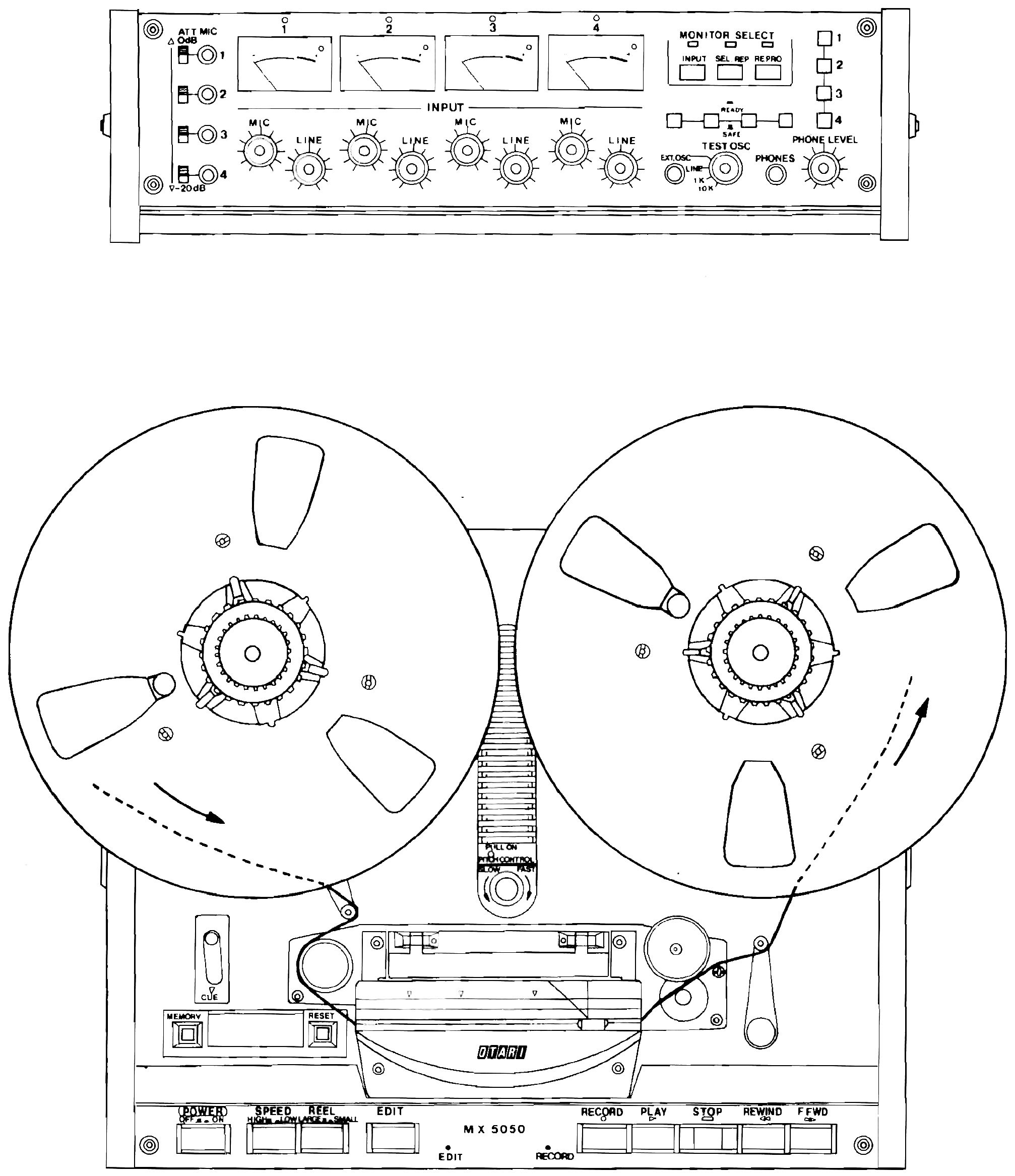
Figure 1-1 MX-5050 MK III-4 Major Components
1-1-(2) RECORD/REPRODUCE ELECTRONICS↑ TOP
FEATURES
(1) The RECORD/REPRODUCE amplifier unit is interconnected to the transport unit by just the connectors.
(2) Available sound applications are a SEL/REP. function for overdubbing: SOUND WITH SOUND, SOUND ON SOUND, etc., carried out by the PUNCH-IN and PUNCH-OUT functions of the transport control.
(3) This machine provides both input and output level switches, selectable on the printed circuit board.
(4) For optimum performance corresponding to the tape used, the Record bias, level, and equalizer controls can be accurately adjusted from the adjusting panel.
(5) Low frequency compensation controls are provided for possible accurate alignment of low frequency characteristics to meet the tape to be used.
1-2 STANDARD ACCESSORIES↑ TOP
The MX-5050 MK III-4 is supplied with the standard accessories listed in Table 1-1.
Table 1-1 Standard Accessories
| Description | Quantity | Otari Part Number |
|---|---|---|
| Power Cord | 1 | PZ9D003 |
| NAB Hub Reel Hold Down Knob (10 1/2'') | 2 | KWOHC |
| NAB Empty Reel (10 1/2'') | 1 | ZA-51H |
| Instruction & Maintenance Manual | 1 | OS3-035 |
1-3 OPTIONAL ACCESSORIES↑ TOP
Available optional accessories are listed in Table 1-2.
Table 1-2 Optional Accessories
| Description | Otari Part Number |
|---|---|
| Remote Control Unit | CB-102 |
| Cleaning Kit | ZA-51B |
| Tape Deck Pedestal | ZA-52L |
| Extension Board Ass'y | PB-77X |
1-4 SPECIFICATIONS↑ TOP
The specifications of the MX-5050 MK III-4 are as listed in Table 1-3.
Table 1-3 Specifications
| Tape Width and Tracks: | 1/2 inch (12.7 mm) tape 4 tracks (0.037 inch or 1.9 mm track width) |
| Tape Speeds: | 7 1/2 and 15 ips (19.05 and 38.1cm/sec.) Maximum deviation: ±0.2% measured with 1.5 mil (0.038 mm) tape |
| Reel Sizes: | 1/2 ×10 1/2 inch NAB |
| Heads: | Three four track in-line: erase (ferrite), record, reproduce (both hard permalloy) |
| Motors: Capstan: | DC servo controlled motor (Pitch control range ±7%) |
| Reels: | Two torque motors |
| Rewind Time: | Appoximately 100 seconds for 2,500 ft (760 m) NAB reel |
| Operating Position: | Horizontal [Tabletop type] |
| Power Requirements: | 100, 117, 220, 240 volts, 50 or 60 Hz, single phase AC. |
| Power Consumption | 110 watts |
| Operating Environment: | 40° to 104°F (5° to 40°C) 20% to 80% Relative Humidity |
| Storage Environment: | -5° to 113°F (-20° to 45°C) |
| Dimensions and Weight: | Dimensions: 438 mm width, 662 mm depth, 488 mm height. 17.3 " width, 26.1" depth, 19.2" height Weight: 32 kg, 71 lbs. |
| Mounting | Dark leatherette-finished cabinet. |
| Remote Control Unit: | An optional remote control unit is used to control the record, play, stop, rewind, and fast forward modes. (CB-102) |
| Connectors: | LINE INPUT, LINE OUTPUT: standard three-pin XLR. MICROPHONE, EXT OSC: standard single-conductor phone jack PHONES: standard two-conductor phone jack |
| Inputs: LINE: | Minimum -6 or -18 dBm switchable, unbalanced 50 kohm. |
| MICROPHONE: | Minimum -70 dBm, unbalanced. Applicable microphone impedance: 150 ohm to 1 kohm. The microphone attenuator switch may be set to the 0 or -20 dB position depending on the circumstances. |
| EXT OSC: | Minimum -18 dBm, unbalanced 10 kohm. |
| Outputs: LINE: | +4 or -8 dBm switchable, unbalanced. Load impedance: more than 600 ohm. Maximum line output level: +21 dBm with 600 ohm load |
| Headphone Jack: | -19 dBm with an 8 ohm load Load impedance: 8 ohm or greater |
| Equalization: | NAB or IEC for 7 1/2 and 15 ips. |
| Frequency Response: | REC/PLAY 15 ips: 40Hz to 20 kHz ±2 dB 7 1/2 ips: 30Hz to 18 kHz ±2 dB SEL/REP 15 ips: 40Hz to 16 kHz ±3 dB 7 1/2 ips: 30Hz to 12 kHz ±3 dB Specifications refer to a 1 kHz reference when recorded on 3M #226. |
Signal to noise ratio:
| Tape speed \ EQ. | NAB | IEC | ||
|---|---|---|---|---|
| Weighted | Unweighted | Weighted | Unweighted | |
| 15 ips | 71 dB | 69 dB | 71 dB | 69 dB |
| 7 1/2 ips | 71 dB | 69 dB | 71 dB | 69 dB |
| Crosstalk: | greater than 60 dB |
| Wow and Flutter: | NAB weighted: 15 ips: less than 0.05% 7 1/2 ips: less than 0.06% |
| Distortion: | less than 0.5% at 1 kHz at 250 nWb/m. |
| Erase Efficiency: | greater than 70 dB. |
| Test Oscillator Frequency: | Nominal 1 kHz and 10 kHz. |
| Bias and Erase Frequency: | 200 kHz |
| Peak indicator: | Trigger level: 1040 nWb/m (15 dB above AMPEX operating level) recorded flux level. |
Notes:
- Signal to noise ratio is measured with respect to a recorded level of 1,040 nWb/m to biased tape noise when using 3M #226, magnetic tape. Unweighted: Using a 30 Hz to 18 kHz RC filter to eliminate noise outside the audio spectrum Weighted: Using an NAB or ASA "A" weighting filter and a 1 kHz reference
- Main schematic diagrams are attached to the last part of this manual.
- OTARI reserves the right to change specifications without notice and/or obligation.