MARK III/4 Instruction and Maintenance Manual — Digital Edition · Part 0 · scan pages 1-12
Front Matter
OS3-035
 ⤢ zoomThe OTARI wordmark logo in block capital letters, the lockup printed on the manual's cover.
OTARI
MX-5050 MK III-4
PROFESSIONAL RECORDER
INSTRUCTION AND MAINTENANCE MANUAL
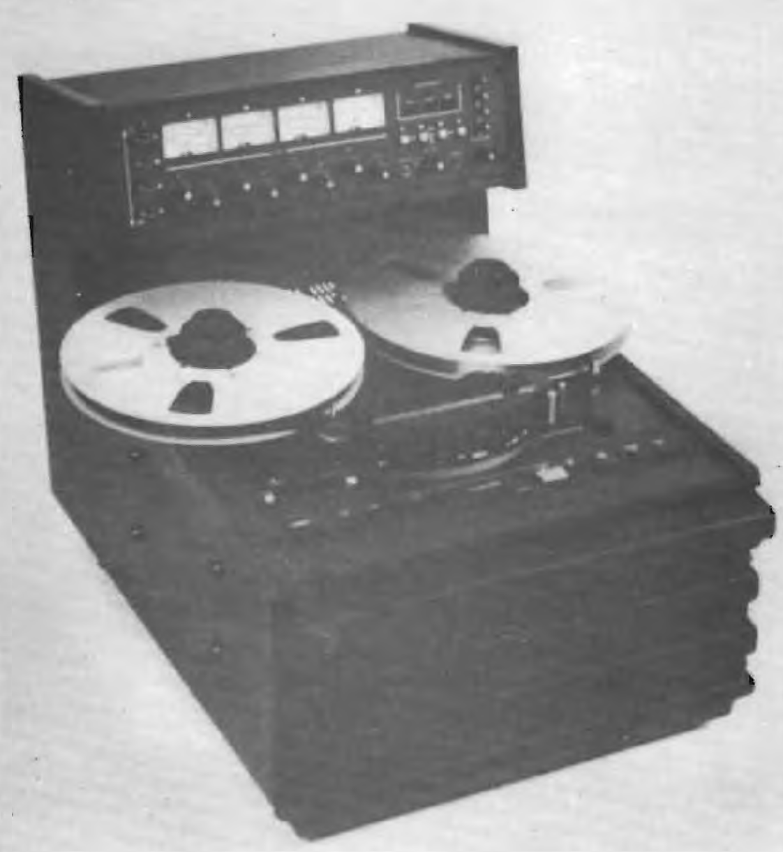 ⤢ zoomHalftone cover photo of the MX-5050 MK III-4 recorder, shown at an angle with its reels and control panel.
CAUTION
To prevent fire or shock hazard:
Do not expose this appliance to rain or moisture.
Do not remove back.
No user-serviceable parts inside.
Refer servicing to qualified service personnel.
SAFETY INSTRUCTIONS↑ TOP
-
Read Instructions -- All the safety and operating instructions should be read before the appliance is operated.
-
Retain Instructions -- The safety and operating instructions should be retained for future reference.
-
Heed Warnings -- All warnings on the appliance and in the operating instructions should be adhered to.
-
Follow Instructions -- All operating and use instructions should be followed.
-
Water and Moisture -- The appliance should not be used near water - for example, near a bathtub, washbowl, kitchen sink, laundrytub, in a wet basement, or near a swimming pool, etc.
-
Carts and Stands -- The appliance should be used only with a cart or stand that is recommended by the manufacturer.
-
Ventilation -- The appliance should be situated so that its location or position does not interfere with its proper ventilation.
For example, the appliance should not be situated on a bed, sofa, rug, or similar surface that may block the ventilation openings; or, placed in a built-in installation, such as a bookcase or cabinet that may impede the flow of air through the ventilation openings.
-
Heat -- The appliance should be situated away from heat sources such as radiators, heat registers, stoves, or other appliances (including amplifiers) that produce heat.
-
Power Sources -- The appliance should be connected to a power supply only of the type described in the operating instructions or as marked on the appliance.
-
Grounding or Polarization -- The precautions that should be taken so that the grounding or polarization means of an appliance is not defeated.
-
Power-Cord Protection -- Power-supply cords should be routed so that they are not likely to be walked on pinched by items placed upon or against them, paying particular attention to cords at plugs, convenience receptacles, and the point where they exit from the appliance.
-
Cleaning -- The appliance should be cleaned only as recommended by the manufacturer.
-
Nonuse periods -- The power cord of the appliance should be unplugged from the outlet when left unused for a long period of time.
-
Object and Liquid Entry -- Care should be taken so that objects do not fall and liquids are spilled into the enclosure through openings.
-
Damage Requiring Service -- The appliance should be serviced by qualified service personnel when:
A. The power-supply cord or the plug has been damaged; or
B. Objects have fallen, or liquid has been spilled into the appliance; or
C. The appliance has been exposed to rain; or
D. The appliance does not appear to operate normally or exhibits marked change in performance; or
-
Servicing -- The user should not attempt to service the appliance beyond that described In the operating instructions.
All other servicing should be referred to qualified service personnel.
MX-5050 MK III-4
PROFESSIONAL TAPE RECORDER
INTRODUCTION↑ TOP
This manual provides descriptive information, installation, operation, maintenance and normal adjustment instructions for the Otari MX-5050 MK III-4 Professional Tape Recorder.
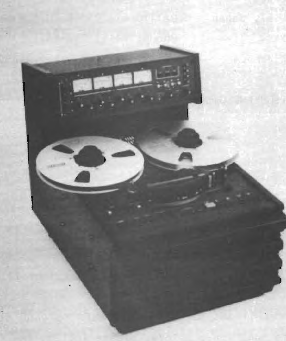 ⤢ zoomPhoto of the MX-5050 MK III-4 recorder facing forward, captioned MX-5050 MK III-4 Recorder below it.
MX-5050 MK III-4 Recorder
COMMUNICATION WITH OTARI↑ TOP
FOR SERVICE INFORMATION AND PARTS
OTARI PRODUCTS are manufactured under strict quality control and each unit is carefully tested and inspected prior to shipment from our factory.
If, however, adjustment or technical support becomes necessary, replacement parts are required or technical questions arise, please contact your nearest Otari dealer or write to:
OTARI ELECTRIC CO., LTD.
4-29-18, Minami Ogikubo,
Suginamiku, Tokyo, 167, Japan
Phone: (03) 333-9631
Telex No.: OTRDENKI J26604
OTARI CORPORATION
2 Davis Drive, Belmont
California 94002, U.S.A.
Phone: (415) 592-8311
Telex No.: TWX 910-376-4890
OTARI ELECTRIC DEUTSCHLAND GmbH
Gielen Strasse
4040 Neuss 1
F.R. Germany
TEL :02101-274011 , 12
TLX :418517691
Another part of Otari's continuous technical support program for our products is the continuous revision of manuals as the equipment is improved or modified. In order to receive information and service applicable to your equipment, and for technical support to function properly, please include the following information, most of which can be obtained from the nameplate on the equipment when you communicate with Otari.
- Model Number
- Serial Number
- Date of purchase
- Name and address of dealer from whom unit was purchased
- Power requirements (voltage and frequency)
- Manual number to which you are referring
* Addenda * (MX-5050 BQ-2,MK-3-4,MK-3-8)↑ TOP
External Capstan Speed Control↑ TOP
For a special application such as interfacing with synchronizers or controllers,an external capstan speed control can be performed to connecting them to the "LOCATOR" connector located on the rear panel.
Capstan speed is controlled with the DC voltage (range:+-13V) which is fed to the "LOCATOR" connector PIN No.1 and No.2.
Capstan speed continuously varies in proportion to DC voltage;
At the -13V of DC voltage,capstan speed is minimum.
At the 0V of DC voltage,capstan speed is nominal. (15,7-1/2ips)
At the 13V (+8V on 15ips) of DC voltage,capstan speed is maximum.
To perform external capstan speed control,proceed as follows.
- Referring to SECTION 5-5 "FUSE REPLACEMENT of the manual,expose the Control P.C.B.
- Position two DIP switches on the Control P.C.B.,SW-2 and SW-3,to "NORMAL" and "EXT".
- Referring to the Table-2 "Pin Assignment",solder respective leads on connector,mated with the "LOCATOR" connector. Part No. of the mating connector : CN216203
- Connect the equipment to a synchronizer,or a controller.
Table-1 Control DC voltage and Capstan speed
| Nominal speed (ips) | Control DC voltage (V) | Capstan speed (%) |
|---|---|---|
| 15 | -13 | -60 |
| 15 | 0 | 0 |
| 15 | 8 # | +70 |
| 7-1/2 | -13 | -60 |
| 7-1/2 | 0 | 0 |
| 7-1/2 | 13 | +210 |
# On 15ips,Capstan speed is limited at the value of DC 8V.
(Ver.1.0)
Table-2 Pin assignment of the "LOCATOR" connector
| PIN No. | Description | Note |
|---|---|---|
| 1 # | GND,F | GND of EXT. CONT |
| 2 # | EXT.CONT | Capstan speed control DC voltage (range:+-13V) |
| 3 | CLOCK | Tach pulses (TTL logic convention) Frequency:40Hz at 15ips |
| 4 | DIR.(Rev/Fwd) | Transport Direction (TTL logic convention) |
| 5 | N.C. | |
| 6 | 15ips | Tape speed command (24V/open) |
| 7 | 7-1/2ips | |
| 8 | (3-3/4ips) | |
| 9 | N.C. | |
| 10 | RECORD | Transport control (TTL logic convention :active "LOW") |
| 11 | F.FWD | |
| 12 | RWD | |
| 13 | PLAY | |
| 14 | STOP | |
| 15 | N.C. | |
| 16 | 5V | Maximum load:50mA |
# On PIN No.1 and 2,a single-conductor shielded cable should be used.
(Ver.1.0)
TABLE OF CONTENTS↑ TOP
LIST OF ILLUSTRATIONS AND TABLES↑ TOP
| Figure | Title | Page |
|---|---|---|
| 1-1 | MX-5050 MK Ⅲ -4 Major Components | 1-3 |
| 2-1 | Dimensions | 2-3 |
| 2-2 | MIC ATT | 2-4 |
| 2-3 | Adjusting Panel | 2-4 |
| 2-4 | Input/Output Assembly Connector Wiring | 2-9 |
| 3-1 | Reel Hold Down Knob | 3-12 |
| 3-2 | Tape Threading | 3-13 |
| 3-3 | Tape Splicing Block | 3-18 |
| 5-1 | Lifting the Head Cover | 5-2 |
| 5-2 | Demagnetizing | 5-4 |
| 5-3 | Lubrication | 5-5 |
| 5-4 | Voltage Selection Terminal | 5-7 |
| 5-5 | Access for Line Voltage Conversion | 5-8 |
| 5-6 | Main Power Fuse Location | 5-9 |
| 5-7 | Internal Fuse Location | 5-10 |
| 5-8 | Rotating Control P.C.B. | 5-11 |
| 6-1 | Tape Transport Access | 6-1 |
| 6-2 | Brake Measurement | 6-4 |
| 6-3 | Brake Assembly Location | 6-4 |
| 6-4 | Pinch Roller Pressure Measurement | 6-6 |
| 6-5 | Pinch Roller Pressure Adjustment | 6-6 |
| 6-6 | Capstan Servo Control P.C.B. | 6-7 |
| 6-7 | Control Timing Chart | 6-8 |
| 6-8 | Recording Process Timing Chart | 6-9 |
| 7-1 | Filter Schematics | 7-3 |
| 7-2 | Test Tape Loading | 7-9 |
| 7-3 | Electronics Access | 7-12 |
| 7-4 | Reproduce System Block and LevelDiagram | 7-13 |
| 7-5 | Head Assembly | 7-14 |
| 7-6 | Location of Record/Reproduce Electronics | 7-16 |
| 7-7 | Overall Frequency Response | 7-19 |
| 7-8 | Record System Block and Level Diagram | 7-20 |
| 7-9 | Bias Current v.s. Output and Distortion | 7-20 |
| 7-10 | Input v.s. Output and Distortion | 7-21 |
| 7-11 | Location of Record/Reproduce Electronics | 7-21 |
| 7-12 | Location of AMP. Control Electronics | 7-24 |
| 8-1 | Reel Motor Mounting | 8-1 |
| 8-2 | Brake Assembly | 8-2 |
| 8-3 | Location of DC Servo Capstan Motor | 8-5 |
| 8-4 | Pinch Roller Removal | 8-6 |
| 8-5 | Head Assembly | 8-8 |
| 8-6 | Head Alignment | 8-8 |
| Table | Title | Page |
|---|---|---|
| 1-1 | Standard Accessories | 1-5 |
| 1-2 | Optional Accessories | 1-5 |
| 1-3 | Specifications | 1-6 |
| 2-1 | Standard Switch Position on Shipment | 2-4 |
| 2-2 | Rear Connector Panel | 2-5 |
| 3-1 | Tape Transport Controls and Indicators | 3-1 |
| 3-2 | Record/Reproduce Electronics Controls and Indicators | 3-7 |
| 4-1 | Test and Maintenance Equipment | 4-1 |
| 4-2 | Flutter Test Tapes | 4-2 |
| 4-3 | Reproduce Alignment Test Tape | 4-2 |
| 5-1 | Record Level | 5-6 |
| 5-2 | Fuse Information | 5-10 |
| 6-1 | Braking Force Specifications | 6-3 |
| 7-1 | Signal-to-Noise Specifications | 7-4 |
| 7-2 | Flutter and Wow Specification | 7-11 |
| 7-3 | Equalizer Time Constants & Fluxivity | 7-16 |
| 7-4 | Standard Level | 7-24 |
| 9-1 | Troubleshooting Hints for Amplifiers | 9-2 |
| 9-2 | Troubleshooting Hints for Transport | 9-2 |
| 10-1 | Safety Component | 10-2 |