MX-5050BII Instruction Manual — Digital Edition · Part 6 · scan pages 65-77
Transport Maintenance
Tape transport maintenance includes procedures for adjusting the supply and take-up reel brakes, the capstan pinch roller pressure and the capstan speed adjustment.
6.1 TRANSPORT ACCESS↑ TOP
To access to the recorder transport, proceed as follows:
(1) Remove the power cable and place the recorder in an upright position.
(2) Remove the rear cover by removing the six cross-recessed screws on the panel (two screws are with studs).
(3) Open the control printed circuit board by removing six cross-recessed screws marked "OPEN".
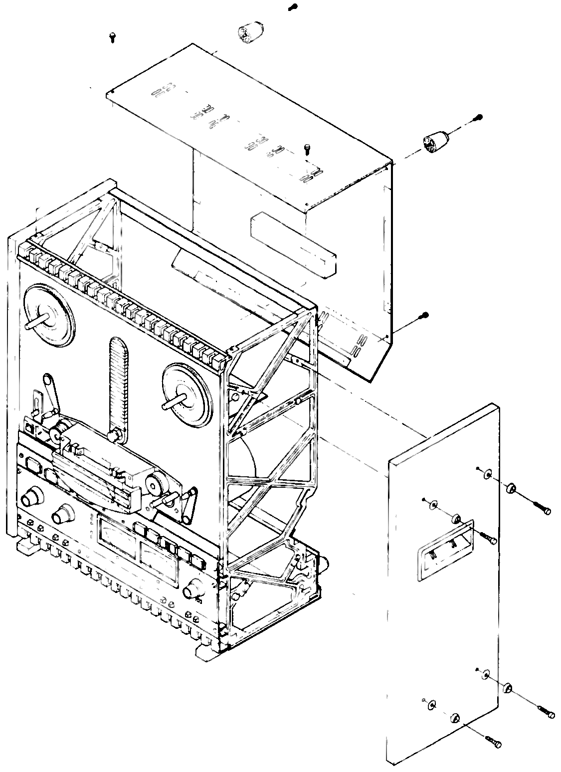 ⤢ zoomIsometric exploded view of the transport with the rear cover, control P.C.B. and side panel lifting away, showing their mounting screws.
Fig. 6-1 Rear Panel and Side Board Removal
(4) Remove the two side panels by removing the four hex-socket screws on each panel.
6.2 BRAKE ADJUSTMENT↑ TOP
The brake system on each reel stops reel rotation when the stop mode is entered into or when power is removed. The brakes are checked and adjusted with the power removed. Since the brake force is different for each direction of rotation (brake differential), and there is a single adjustment, the force is checked and adjusted for the best compromise force in each direction.
In the following steps, an empty 10-1/2 inch diameter NAB reel (4-1/2 inch diameter hub) is used with string wrapped on the reel. A spring scale is attached to a small loop formed in the free end of the string.
If 10-1/2 inch diameter NAB reel (4-1/2 inch diameter hub) is not available, a 7 inch diameter reel (2-1/4 inch diameter hub) may be used but all readings must be multiplied by a factor of 2. Proceed as follows:
Refer to Table 6-1 for the breaking force specifications.
(1) Place an empty 10-1/2 inch diameter NAB reel on the supply reel turntable. Secure with a hold-down knob.
(2) Wind string by few turns counterclockwise on the hub. Tie a loop in the free end of the string.
(3) Insert the hook of a 0-16 ounce or 0-32 ounce spring scale through the loop and hold the spring scale upright as shown in Fig. 6-2.
(4) Pull on the scale slowly to make the reel rotate counterclockwise (direction "B" in Fig. 6-2). While being sure the string does not rub against either flange, note the scale reading. The reading should be 7.9 to 9.7 ounces (225 to 275 grams).
(5) Wind the string in a clockwise direction on the supply reel.
(6) Repeat steps (3) and (4) to make the reel rotate clockwise (direction "A" in Fig. 6-2). The reading should be 3.6 to 4.5 ounces (100 to 125 grams).
(7) If the readings were low in both directions, remove the brake spring (shown in Fig. 6-3) from the existing anchor hole on the brake lever and install the spring in the next hole located farther away from the brake solenoid.
(8) If the readings were high in both directions, move the spring anchor point closer to the brake solenoid.
(9) If the brake spring was moved, repeat steps (2) through (6) to check the results.
(10) Repeat the brake adjustment procedure on the take-up reel. Note that a high braking force is present when the take-up reel is rotated clockwise. The braking force specifications are the same as for the supply reel.
Table 6-2 Braking Force Specifications
| A | 3.6 to 4.5 ounces (100 to 125 grams) |
| B | 7.9 to 9.7 ounces (225 to 275 grams) |
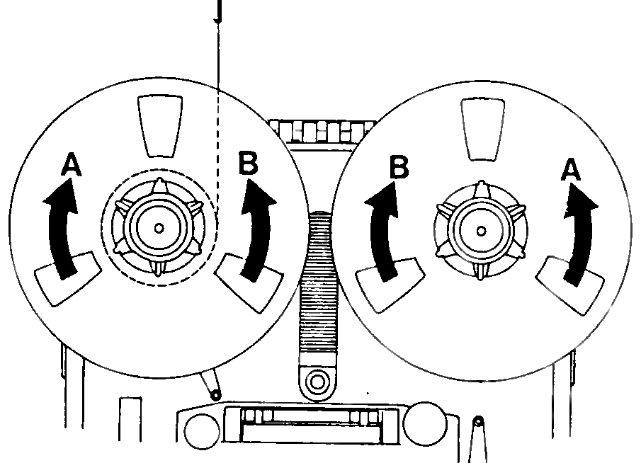 ⤢ zoomTwo views of a tape reel with rotation-direction arrows A and B, showing the hook of a spring scale inserted through a loop of string wound on the hub.
Fig. 6-2 Brake Measurement
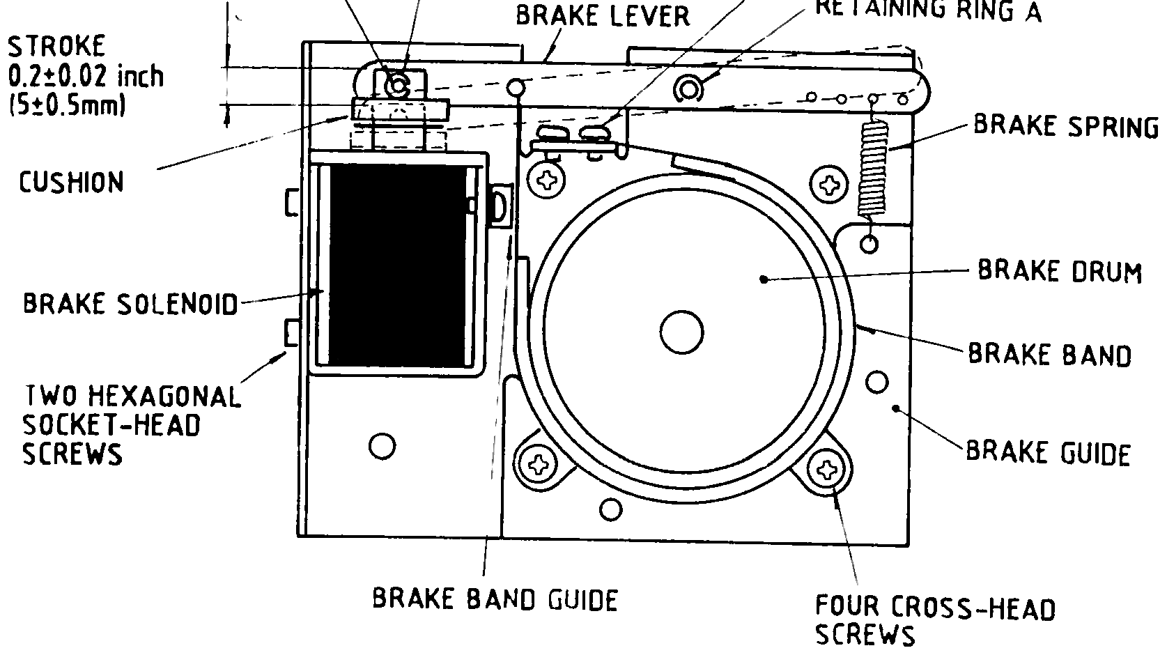 ⤢ zoomLabeled cutaway of the brake solenoid, lever, spring, drum and band assembly, with the two retaining rings and their mounting screws called out.
Fig. 6-3 Brake Assembly Location
6.3 CAPSTAN PINCH ROLLER PRESSURE ADJUSTMENT↑ TOP
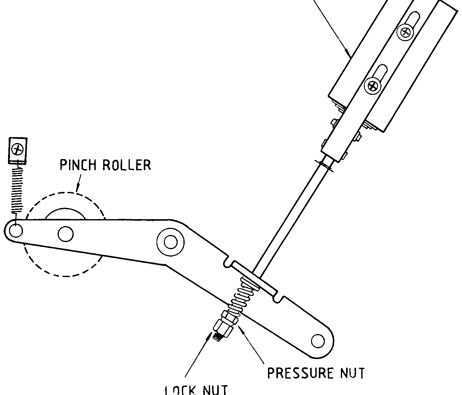
The capstan pinch roller's pressure against the capstan is determined by the capstan solenoid spring. This force is adjusted by means of the nut shown in Fig. 6-5. The nut is adjusted to obtain a force of 6.4 ~ 7.0 pounds. The resistance of the solenoid coil rises with the temperature and causes the solenoid's force to decrease. Therefore, do not adjust the pinch roller's pressure until the recorder has been operated in the play mode for at least 30 minutes. The following procedure should be adhered to.
(1) Use adhesive tape to hold the takeup-tension-arm safety switch in an upright position so that the safety switch is not activated.
(2) Tie string together to form a continuous loop. Place one end of the loop around the capstan pinch roller shaft.
(3) Press the PLAY push-button. The pinch roller will move to make contact with the capstan and both will rotate.
(4) Hook a 0 to 10 pound spring scale to the other end of the cord and pull the cord taut, straight to the center of the capstan as is shown in Fig. 6-4. Do not let the cord come into contact with the rotating pinch roller.
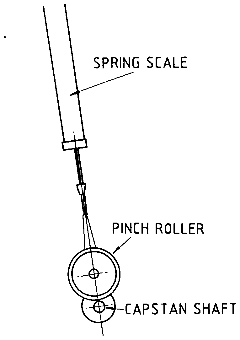 ⤢ zoomSpring scale hooked to a cord looped around the pinch roller, pulled taut toward the capstan shaft.
Fig. 6-4 Pinch Roller Pressure Measurement
 ⤢ zoomPinch roller lever and solenoid assembly with the pressure nut and lock nut on the spring-loaded adjustment rod called out.
Fig. 6-5 Pinch Roller Pressure Adjustment
(5) Pull on the scale and note the scale reading when the pinch roller just loses contact to the capstan (the pinch roller stops rotating). The scale reading should be 6.4 ~ 7.0 pounds.
(6) If a proper scale reading was not obtained in step (5), loosen the locknut and adjust the pressure nut as required. (Turning the pressure nut towards the spring increases pinch roller pressure.) Tighten the locknut.
(7) After adjustment has been completed, check that the solenoid bottoms within the solenoid coil (the pinch roller can easily be pushed away from capstan). If the solenoid does not bottom, loosen the locknut and turn the pressure nut away from the spring until the solenoid bottoms. Recheck the pressure adjustment and tighten the locknut.
6.4 SPEED CONVERSION AND SPEED ADJUSTMENT↑ TOP
The MX-5050BII series units can be operated at 3 tape speeds. The "high" setting is for 15 and 7-1/2 ips, and the "low" setting is for 7-1/2 and 3-3/4 ips. The conversion procedure requires only that you switch the speed selection switch and adjust the tape speed.
We also recommend that you re-adjust the amplifier to obtain optimum performance.
(1) Remove the 6 screws attaching the rear panel to the tape deck. Remove the panel.
(2) Remove the 4 allen screws that hold the right side panel to the frame. Remove the panel.
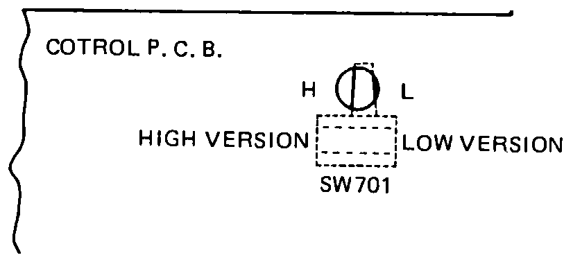
(3) The speed selection switch is located on the big P.C.B. Ass'y as illustrated Fig. 6.6.
(4) Slide the switch to L for 7-1/2 and 3-3/4 or H for 15 and 7-1/2 ips.
(5) Put a speed reference tape for the speed selected on the transport.
(6) Play the tape and measure the frequency of the output signal with a frequency counter.
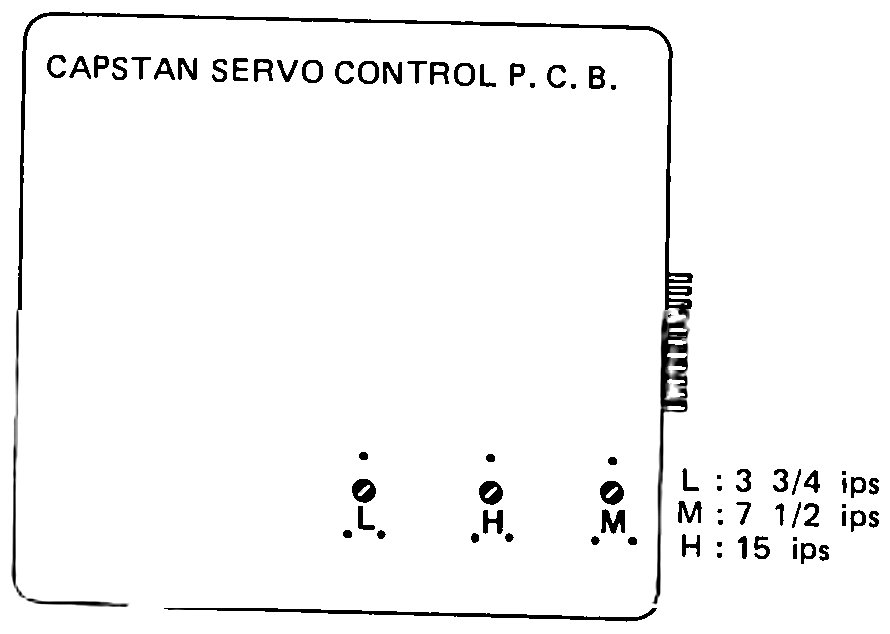
(7) Adjust the appropriate pot on the servo P.C.B. Ass'y near the capstan motor, as illustrated Fig. 6-7, to obtain the reference speed frequency.
(8) Re-install the side and rear panels.
 ⤢ zoomSmall drawing of the control P.C.B. edge with the SW701 slide switch, marked H/L and its HIGH VERSION/LOW VERSION positions.
Fig. 6-6 Location of Tape Speed Conversion Switch
 ⤢ zoomCapstan servo control P.C.B. with its three speed adjustment pots labeled L, H and M, keyed to 3-3/4, 15 and 7-1/2 ips.
Fig. 6-7 Capstan Servo Control P.C.B.
6.5 REEL MOTOR ASSEMBLY REPLACEMENT↑ TOP
6.5.1 REEL TABLE HEIGHT ADJUSTMENT AND REPLACEMENT↑ TOP
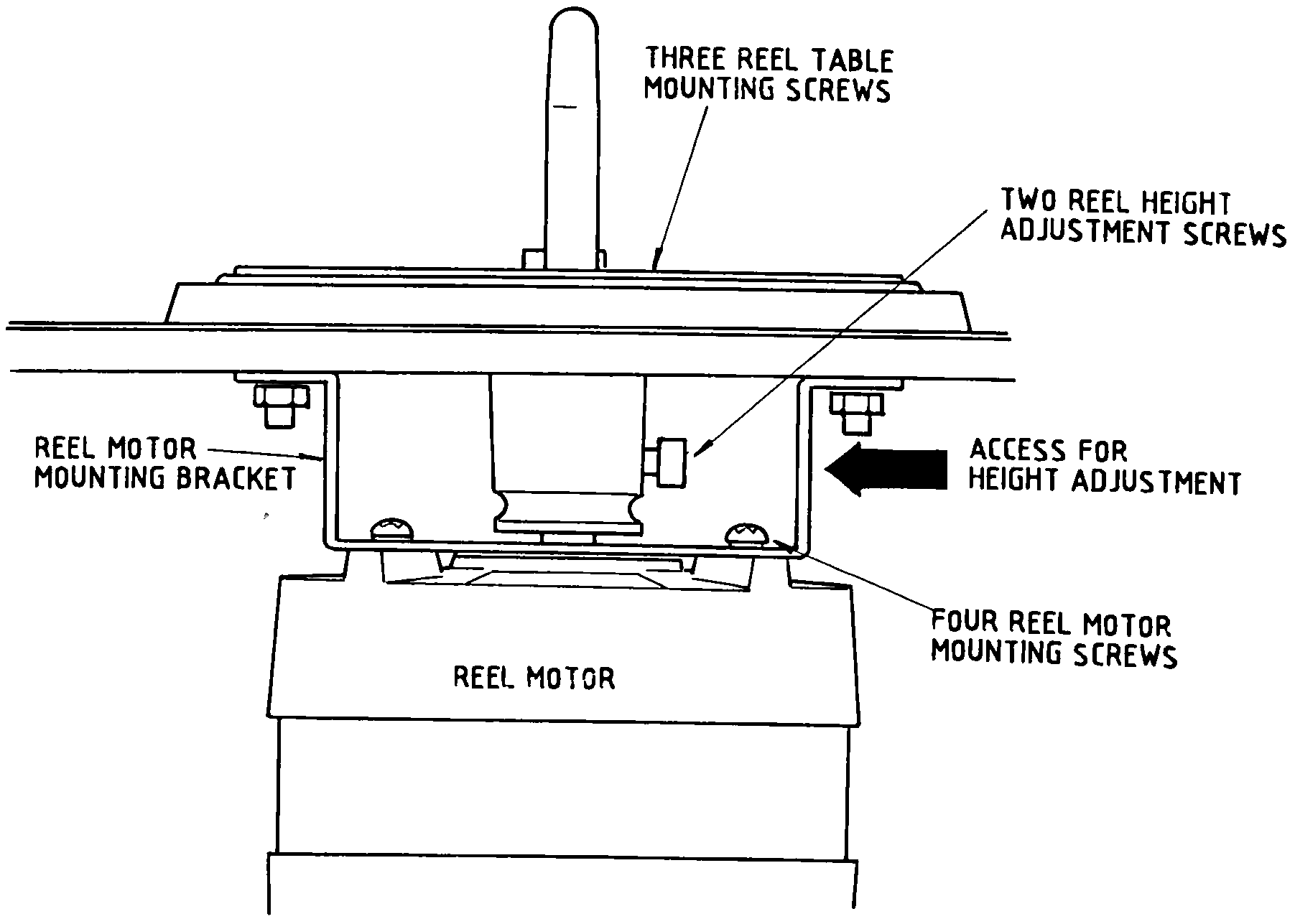
The reel table may be removed by removing the three cross-head screws accessible from the front of the transport. To adjust the reel table height, loosen the two hexagonal socket-head screws shown in Fig. 6-8, adjust the height and retighten the screws.
 ⤢ zoomCutaway of the reel table and motor mount with the reel table mounting screws, reel height adjustment screws and reel motor mounting screws called out.
Fig. 6-8 Reel Motor Mounting
6.5.2 REEL MOTOR REPLACEMENT↑ TOP
To replace the supply or takeup motor proceed as follows:
(1) Loosen the two hexagonal socket-head screws on the reel shaft holder (Fig. 6-8) and remove the reel table and holder.
(2) Tag and unsolder the motor leads attached to the printed circuit board.
(3) Remove the four motor mounting cross-head screws, accessible from the front of the transport.
(4) Remove two capscrews holding brake drum on to the reel motor shaft and take out the brake drum.
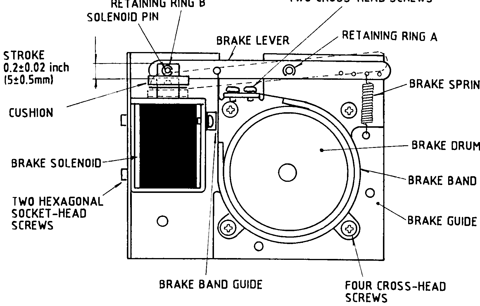
(5) Remove the brake assembly by removing the four brake assembly mounting screws on the bottom of the reel motor as shown in Fig. 6-9.
 ⤢ zoomExploded cutaway of the brake drum assembly with the retaining rings, solenoid pin, brake lever, spring, drum, band and their mounting screws called out.
Fig. 6-9 Brake Assembly
6.5.3 BRAKE BAND AND SOLENOID REPLACEMENT↑ TOP
When a new brake band or new brake solenoid is installed (Fig. 6-9), it is necessary to position the brake guide and/or brake solenoid to ensure that is uniform brake band clearance around the brake drum when the solenoid is energized. Also, the brake solenoid plunger must bottom in the solenoid housing when the solenoid is energized. When the solenoid is de-energized, the brake band should uniformly contact the drum surface. After installation, perform the brake adjustment procedure in page 6-3 of this manual. After completion of the adjustments, place the recorder in the play mode for 30 minutes. Then press the STOP and PLAY push-buttons to ensure that the solenoid bottoms when it is hot.
To replace the brake band, proceed as follows:
The brake band is replaced together with the brake lever as assembly.
(1) Remove the retaining ring "A" and "B", and remove the brake spring.
(2) Remove the two cross-head screws, and replace the brake band and brake lever.
To replace the brake solenoid, proceed as follows:
(1) Remove the brake spring.
(2) Remove retaining ring B on the solenoid pin and remove the solenoid pin.
(3) Remove the solenoid housing and plunger by removing the two hexagonal socket screws.
(4) Install a new solenoid housing and plunger and.adjust the solenoid for 0.2 ±0.02 inch plunger stroke by loosing two hexagonal socket-head screws.
6.6 POWER TRANSFORMER REPLACEMENT↑ TOP
To replace the power transformer (refer to EXPLODED VIEW 3), proceed as follows:
(1) Tag and unsolder all transformer leads.
(2) Remove the four M4 nuts that secure the transformer to the transport.
(3) Install a new transformer in the reverse order of removal, and resolder the leads to the terminals on the transformer.
6.7 CAPSTAN MOTOR REPLACEMENT↑ TOP
The capstan motor should be replaced along with the servo control printed circuit board assembly. To replace the capstan motor proceed as follows:
(1) Remove the pinch roller cap by turning the cross-head screw counterclockwise.
(2) Remove the pinch roller from the pinch roller shaft.
(3) Remove two screws attaching the head housing cover to the tape deck. Remove the head housing cover.
(4) Remove three screws that hold the lower head cover (skirt) to the deck panel. Remove the cover.
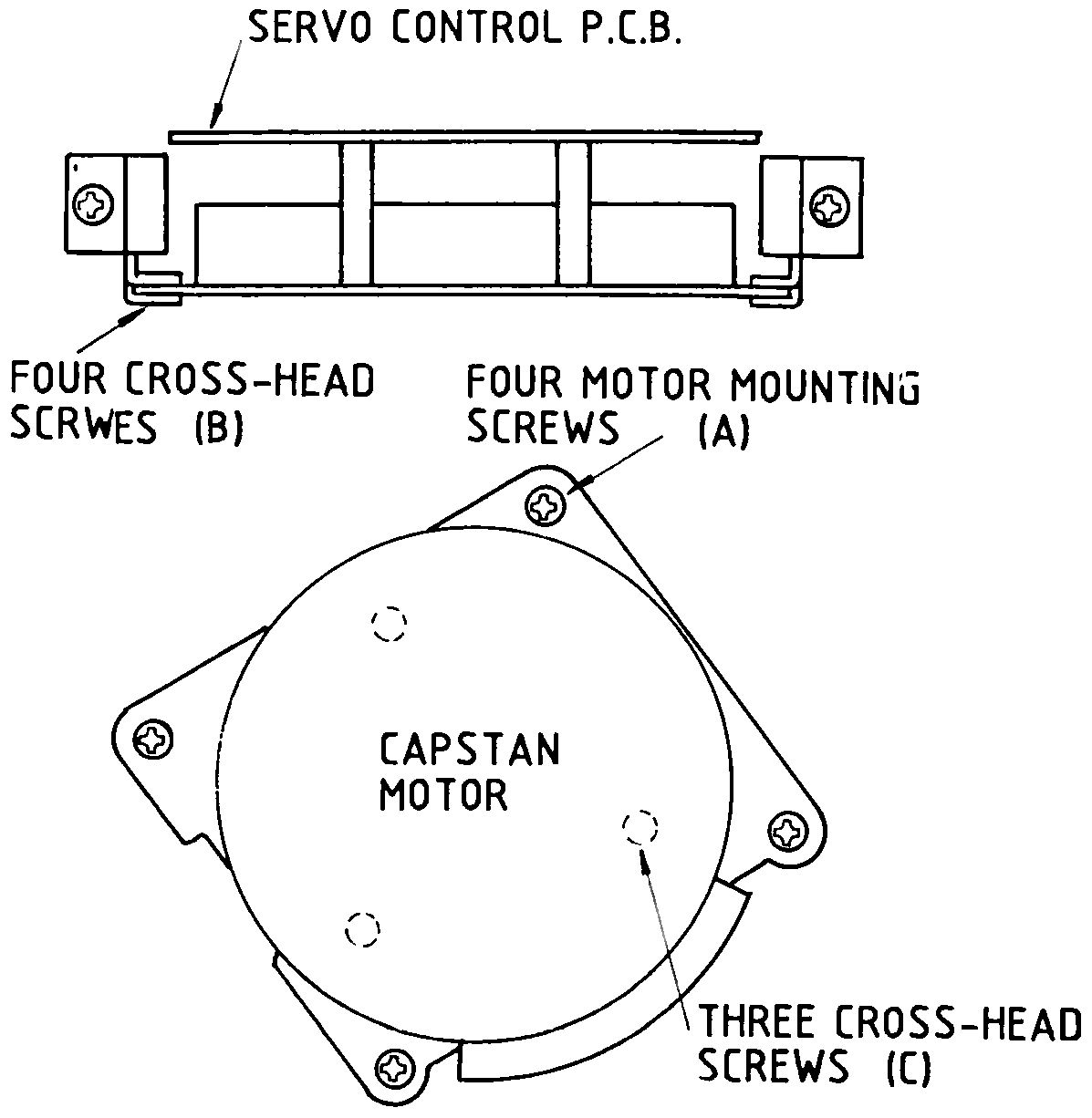 ⤢ zoomSide view of the servo control P.C.B. mounting bracket above a bottom view of the capstan motor mounting plate, with the motor mounting screws (A), bracket screws (B) and motor screws (C) called out.
Fig. 6-10 Location of DC Servo Capstan Motor
(5) Remove the metal dust cap from the capstan shaft by turning it counterclockwise.
(6) Remove the connector on the servo control printed circuit board assembly located above the capstan.
(7) Remove the servo control printed circuit board assembly and its mounting plate by turning the four M3 cross-head screws (B) on the mounting plate.
(8) Remove the capstan mounting plate and capstan motor by removing the four M4 cross-head screws (A) on the mounting plate.
(9) Remove the capstan motor by removing the three M4 cross-head screws (C) on the mounting plate and install a new capstan assembly in the reverse order of removal.
6.8 PINCH ROLLER REPLACEMENT↑ TOP
To replace the pinch roller assembly proceed as follows:
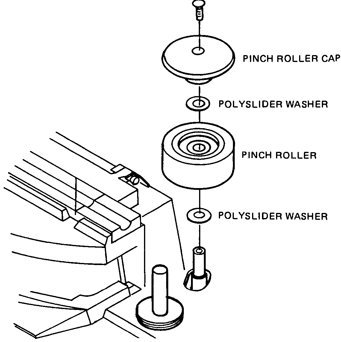
(1) Remove the pinch roller cap by removing the screw on it.
NOTE: There are polyslider washers on both sides of the pinch roller.
(2) Install a new pinch roller, the polyslider washers, and pinch roller cap in the reverse order.
 ⤢ zoomExploded view of the pinch roller cap, polyslider washers, pinch roller and shaft, above a partial view of the transport deck.
Fig. 6-11 Pinch Roller Removal
6.9 HEAD ASSEMBLY REPLACEMENT↑ TOP
This section provides a description of the head assembly, the procedure for changing the head stack, and the adjustment procedure for adjusting head azimuth (tilt), head height, head zenith (perpendicularity), and tape wrap (racking).
These adjustments are required whenever a head stack is replaced.
6.9.1 DESCRIPTION↑ TOP
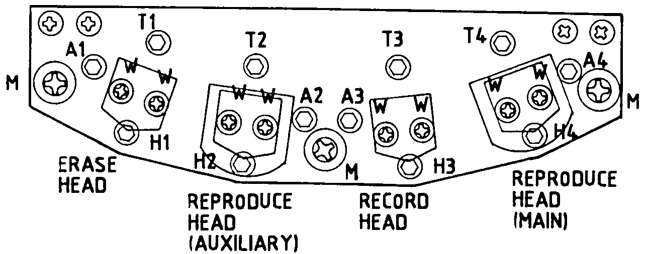
The head assembly is mounted on three tape-guide posts and secured in place by the three screws labeled "M" in Fig. 6-12. The insulating shield for the head assembly printed circuit board is secured by the screws labeled "S".
Each head stack is secured to a bracket by the screws labeled "W" with a spacer between the bracket and the head stack. Each bracket is suspended from the head base by the three spring-loaded screws labeled "H", "A", and "T". Screws labeled "W" are used to adjust tape wrap. Screws labeled "H", "A", and "T" are used to adjust height, azimuth, and zenith.
A head stack may be removed and re-lapped (face resurfaced) if the amount of wear is small and only an indication of poor head-to-tape contact is evident.
Poor contact is the result of improper adjustment and is evidenced by loss of high frequency response of the record or reproduce head stack, difficulty in achieving bias peak (record stack), and insufficient erase stack erasure.
6.9.2 HEAD STACK REPLACEMENT↑ TOP
To change a head stack, proceed as follows:
(1) Remove the AC power cord and lift the head cover.
(2) Remove the three screws labeled "M" and pull the head assembly out from the head connector.
(3) Tag and unsolder (use a low wattage pencil type iron to prevent damage) the leads at the rear terminal of the head stack.
(4) Remove the head stack by removing the two screws labeled "A", "T", and "H".
(5) Install a new head stack and solder the leads.
(6) As a preliminary adjustment, measure the distance between the head base and the bracket at a point near spring-loaded screws "A", "T", and "H". If necessary adjust the screws for equal spacing.
(7) Paint the head face with a soft crayon, run the tape for about ten seconds, and check the crayon rubbed away by the tape. If tape wrap is incorrect, adjust the wrap by loosening the screws labeled "W" as shown in Fig. 6-12.
Head alignment and the following adjustments are necessary whenever the head is replaced.
-
In the case of reproduce head replacement
A. Reproduce equalization adjustment
B. SRL adjustment -
In the case of record head replacement
A. Record bias adjustment
B. Overall frequency response adjustment
C. Record level adjustment -
In the case of erase head replacement
A. Record bias adjustment
(8) Refer to previous section, Section V for more details on those adjustments.
 ⤢ zoomTop view of the head mounting plate with the M, T1-T4, A1-A4, H1-H4 and W screw callouts, and the erase, reproduce (auxiliary), record and reproduce (main) heads labeled.
Fig. 6-12 Head Assembly
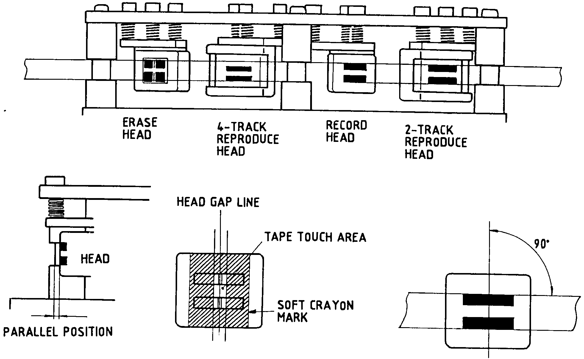 ⤢ zoomHead-stack cross-section row above three diagrams labeled ZENITH, TAPE WRAP and AZIMUTH, illustrating parallel position, head gap line/tape touch area and the 90-degree azimuth angle.
Fig. 6-13 Head Alignment