BQ-II Instruction and Maintenance Manual — Digital Edition · Part 6 · PDF pages 50-58
Tape Transport Maintenance
Tape transport maintenance includes procedures for adjusting the supply and take-up reel brakes, the capstan pinch roller pressure and the tape speed adjustment.
6-1 TRANSPORT ACCESS↑ TOP
To gain access to the recorder transport, proceed as follows:
- Disconnect the power plug and place the recorder in an upright position.
- Remove the rear cover, feet, and deck standby removing ten cross recessed screws on the cover.
- Open the Control P.C. Board by removing six cross-recessed screws marked "OPEN".
- Remove both side boards by removing the four hex socket head screws on each board.
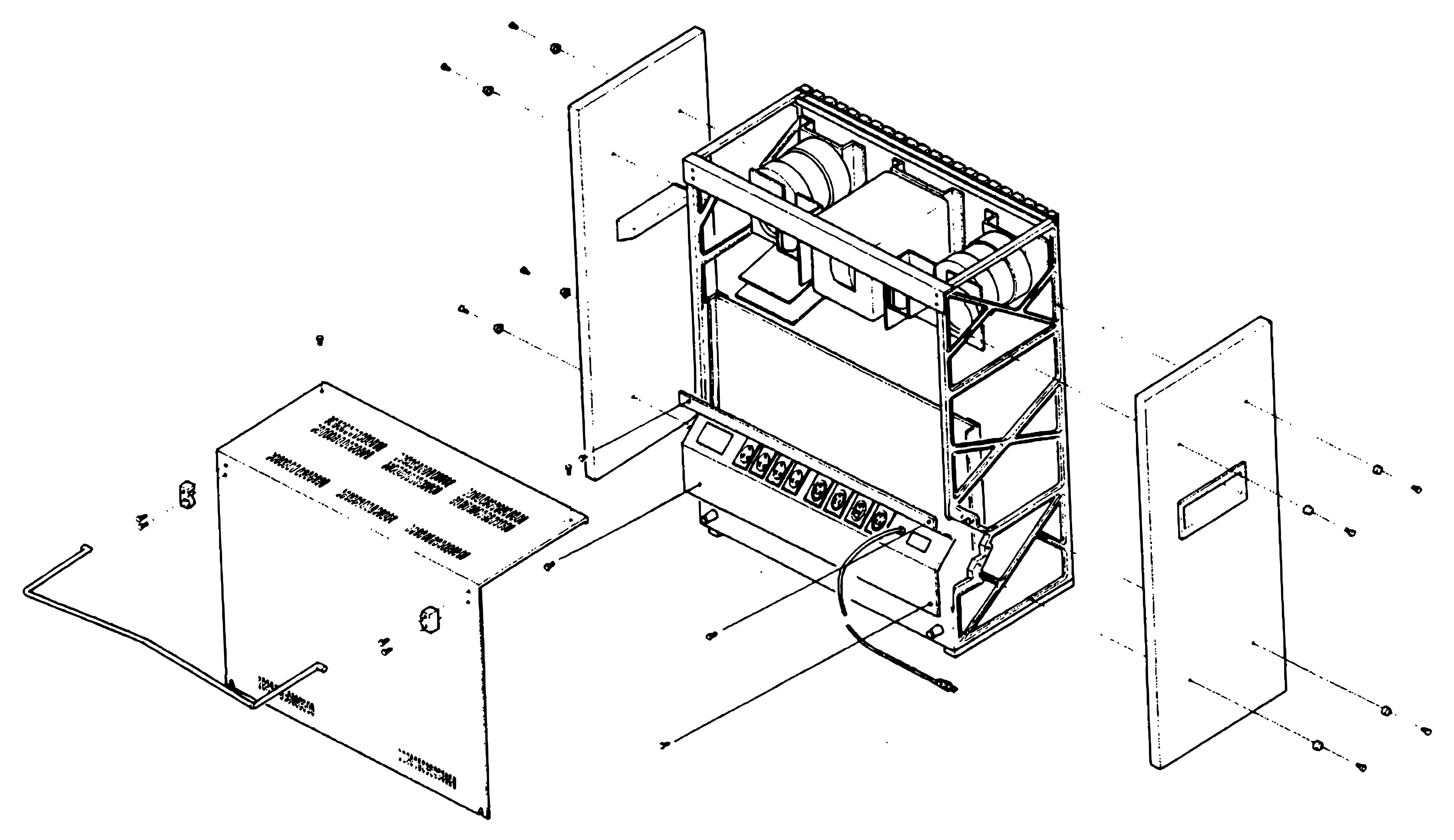 ⤢ zoomAn exploded rear view of the recorder's chassis frame, which carries the two reel motors, with the vented rear cover and its fold-out stand drawn away to one side, a side board lifted off each side, and the rear connector panel with its power cord at the base.
Figure 6-1 Tape Transport Access
6-2 BRAKE ADJUSTMENT↑ TOP
The brake system on each reel stops the rotation of the reel when power is removed.
The brakes are checked and adjusted with the power removed.
Since the brake force is different for each direction of rotation (brake differential), and there is but a single adjustment, the force is checked and adjusted for the best compromise force in each direction.
In the following steps, an empty 10 1/2 inch diameter NAB reel (4 1/2 inch diameter hub) is used and a length of cord or twine is wrapped on the hub.
A spring scale is attached to a small loop formed at the free end of the cord or twine.
If a 10 1/2 inch diameter NAB reel (4 1/2 inch diameter hub) is not available, a 7 inch diameter reel (2 1/4 inch diameter hub) may be used but all readings must be multiplied by a factor of 2.
Refer to Table 6-1 for the braking force specifications.
Proceed as follows:
- Place an empty 10 1/2 inch diameter NAB reel on the supply reel table. Secure with a hold down knob.
- Wind a length of cord or twine a few turns counterclockwise on the hub. Tie a loop at the free end of the cord or twine.
- Insert the hook of a 500 g (0-16 ounce) spring scale through the loop and hold the spring scale upright as shown in Figure 6-2.
- Pull on the scale slowly to make the reel rotate counterclockwise (direction "B" in Figure 6-2). While being sure the cord does not rub against either flange, note the scale reading. The reading should meet the value listed on Table 6-1.
- Wind the cord or twine in a clockwise direction on the supply reel.
- Repeat steps 3 and 4 to make the reel rotate clockwise (direction "A" in Figure
6-2).
The reading should meet the value listed in Table 6-1. - If the readings were low in both directions, remove the brake spring (shown in Figure 6-3) from the existing anchor hole on the brake lever and install the spring in the next hole located farther away from the brake solenoid.
- If the readings were high in both directions, move the spring anchor point closer to the brake" solenoid.
- If the brake spring was moved, repeat steps 2 through 6 to check the results.
- Repeat the brake adjustment procedure on the take-up reel.
Note that a high braking force is present when the take-up reel is rotated clockwise.
The braking force specifications are the same as for the supply reel.
Table 6-1 Braking Force Specifications
| A | 100 to 125 grams (3.6 to 4.5 ounces) |
| B | 225 to 275 grams (7.9 to 9.7 ounces) |
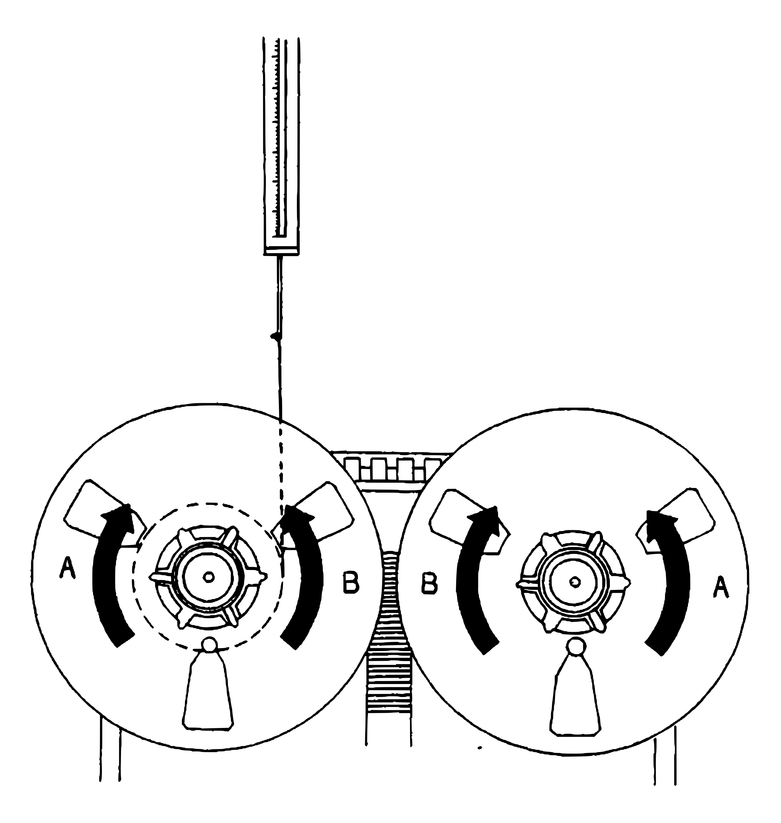 ⤢ zoomA spring scale held upright above the left-hand reel, its hook on a cord wound round the hub, with curved arrows marked A and B on both reels showing the two directions of rotation the braking force is measured in.
Figure 6-2 Brake Measurement
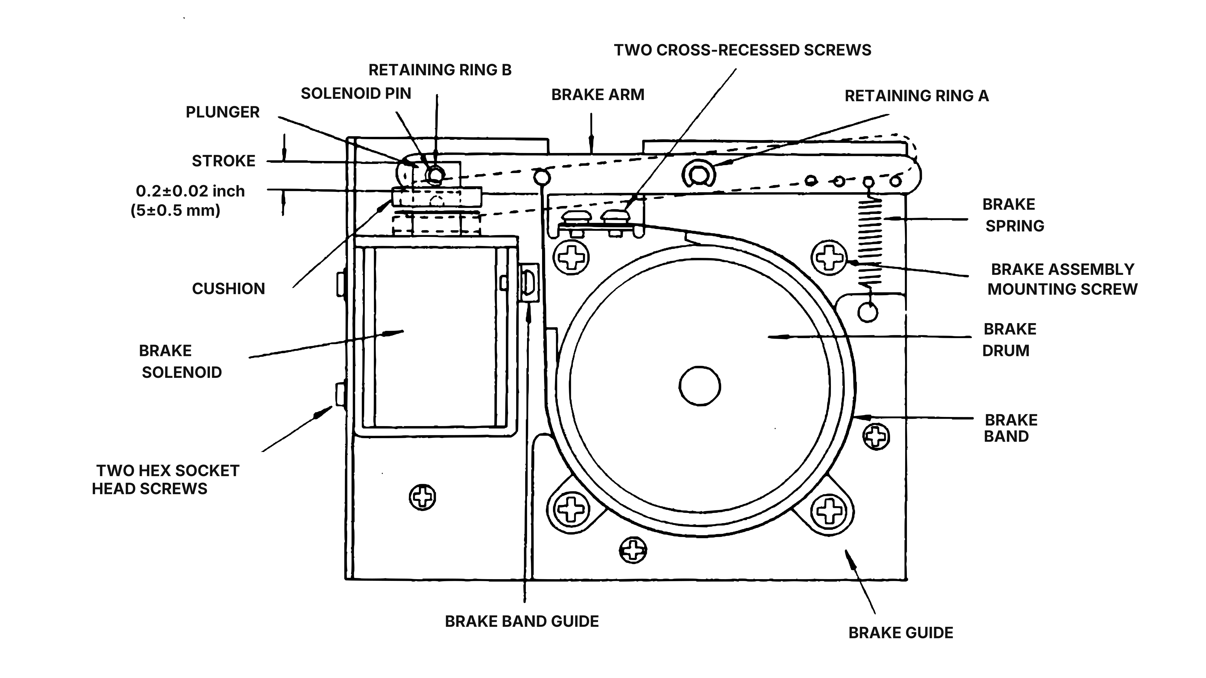 ⤢ zoomA labelled diagram of the brake assembly, showing the brake solenoid, plunger, solenoid pin, brake arm, retaining rings A and B, brake spring, brake drum, brake band, brake band guide and brake guide with their mounting screws.
Figure 6-3 Brake Assembly Location
6-3 CAPSTAN PINCH ROLLER PRESSURE ADJUSTMENT↑ TOP
The capstan pinch roller's pressure against the capstan is determined by the pinch roller solenoid spring. This force is adjusted by means of the nut shown in Figure 6-5. The nut is adjusted to obtain a force of 2.5-2.7 kg (5.5-5.9 pounds). The resistance of the solenoid coil rises with the temperature and causes the solenoid's force to decrease. Therefore, do not adjust the pinch roller's pressure until the recorder has been operated in the play mode for at least 30 minutes. The following procedure should be adhered to.
- Remove both reels from the reel tables for capstan pinch roller pressure adjustment.
- Tie a length of cord or twine together to form a continuous loop. Place one end of the loop around the capstan pinch roller shaft.
- Press the EDIT pushbutton, and then press the PLAY pushbutton. The pinch roller will move to make contact with the capstan and both will rotate.
- Hook a 3 kg (0 to 10 pounds) spring scale to the other end of the cord and pull the cord taut, straight to the center of the capstan as is shown in Figure 6-4. Do not let the cord come into contact with the rotating pinch roller.
- Pull on the scale and note the scale reading when the pinch roller just loses contact with the capstan (the pinch roller stops rotating). The scale reading should be 2.5-2.7 Kg (5.5-5.9 pounds).
- If a proper scale reading was not obtained in step 5, loosen the locknut and adjust the pressure nut as shown in Figure 6-5 . Turning the pressure nut towards the spring increases pinch roller pressure. Tighten the locknut.
- After adjustment has been completed, check that the plunger of the solenoid reaches bottom within the solenoid coil (the pinch roller can easily be pushed away from the capstan). If the plunger of the solenoid does not reach bottom, loosen the locknut and turn the pressure nut away from the spring until the plunger of the solenoid reaches bottom. Recheck the pressure adjustment and tighten the locknut.
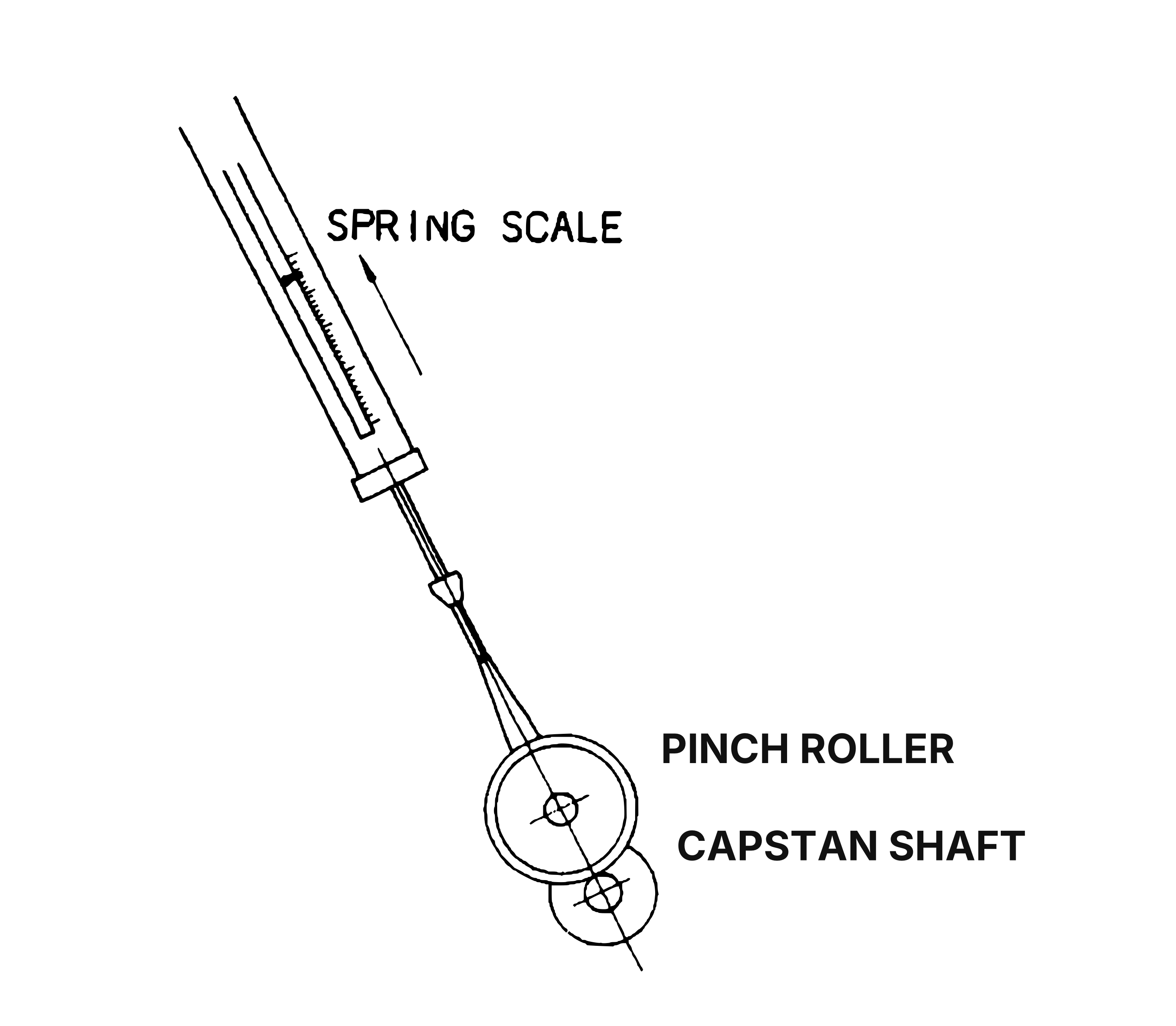 ⤢ zoomA spring scale pulling a cord looped round the pinch roller, drawn taut in a straight line toward the capstan shaft beside it.
Figure 6-4 Pinch Roller Pressure Measurement
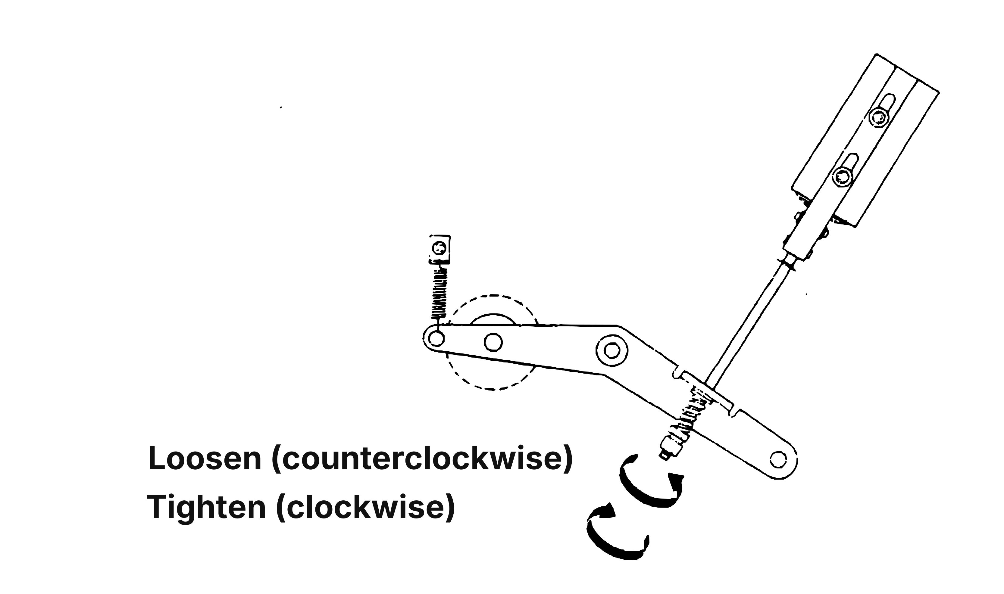 ⤢ zoomThe pinch roller solenoid's pressure-adjustment linkage, with a pressure nut and locknut on a threaded rod and arrows marked Loosen (counterclockwise) and Tighten (clockwise).
Figure 6-5 Pinch Roller Pressure Adjustment
6-4 TAPE SPEED ADJUSTMENT.↑ TOP
The tape speed can only be adjusted on the dc servo capstan motor, by using the speed adjustment controls on the Servo control P.C. Board. This adjustment follows the tape speed measurement in Section 7, and the speed adjustment controls shown in Figure 6-6 are adjusted as necessary.
It is important that the PINCH CONTROL should be placed in the "IN" fixed position during tape speed adjustment.
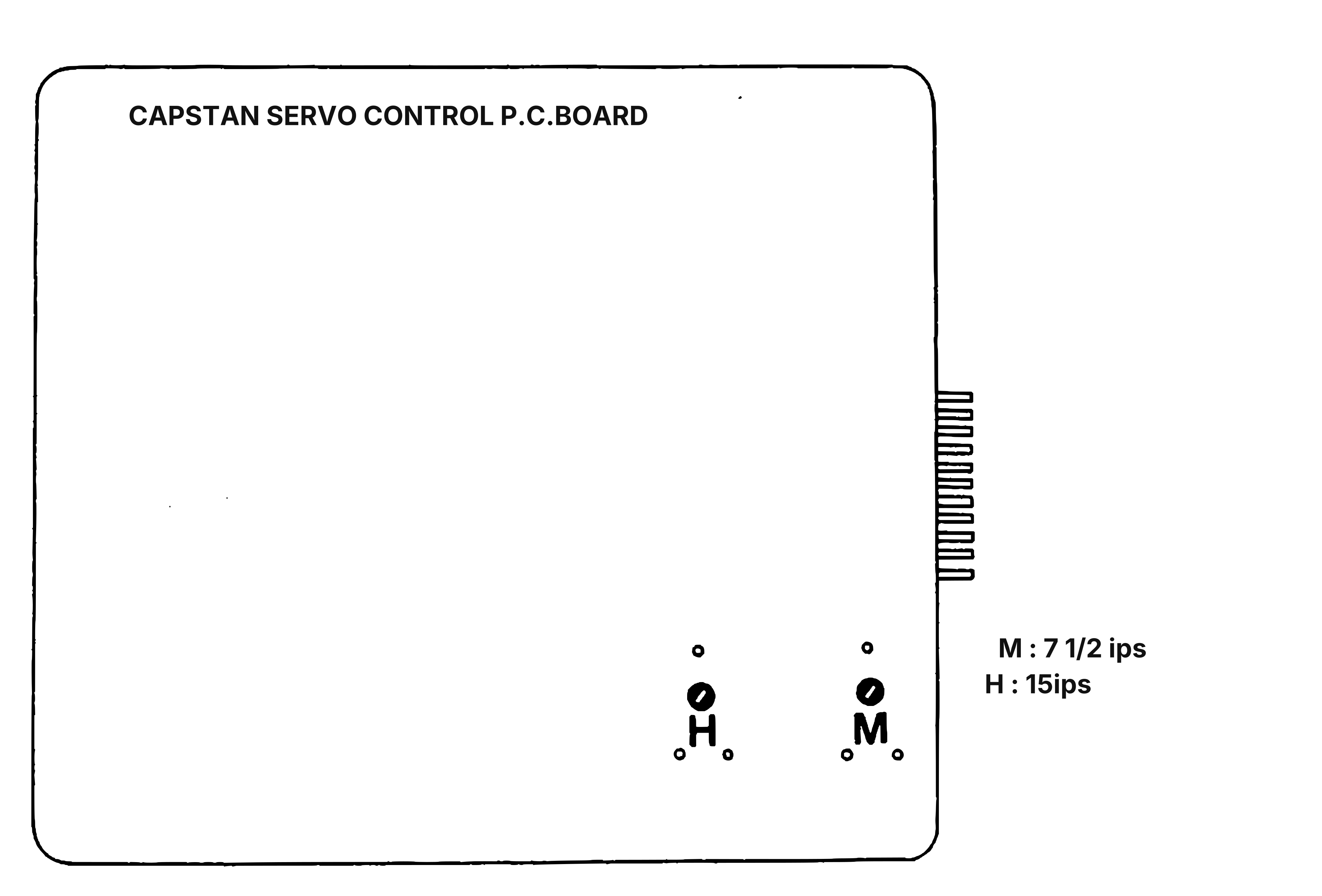 ⤢ zoomThe capstan servo control P.C. board outline with its edge connector at the right and two speed trimmers near its lower edge, H for 15 ips and M for 7 1/2 ips.
Figure 6-6 Capstan Servo Control P.C.B.
6-5 TAPE TRANSPORT TIMING CHART↑ TOP
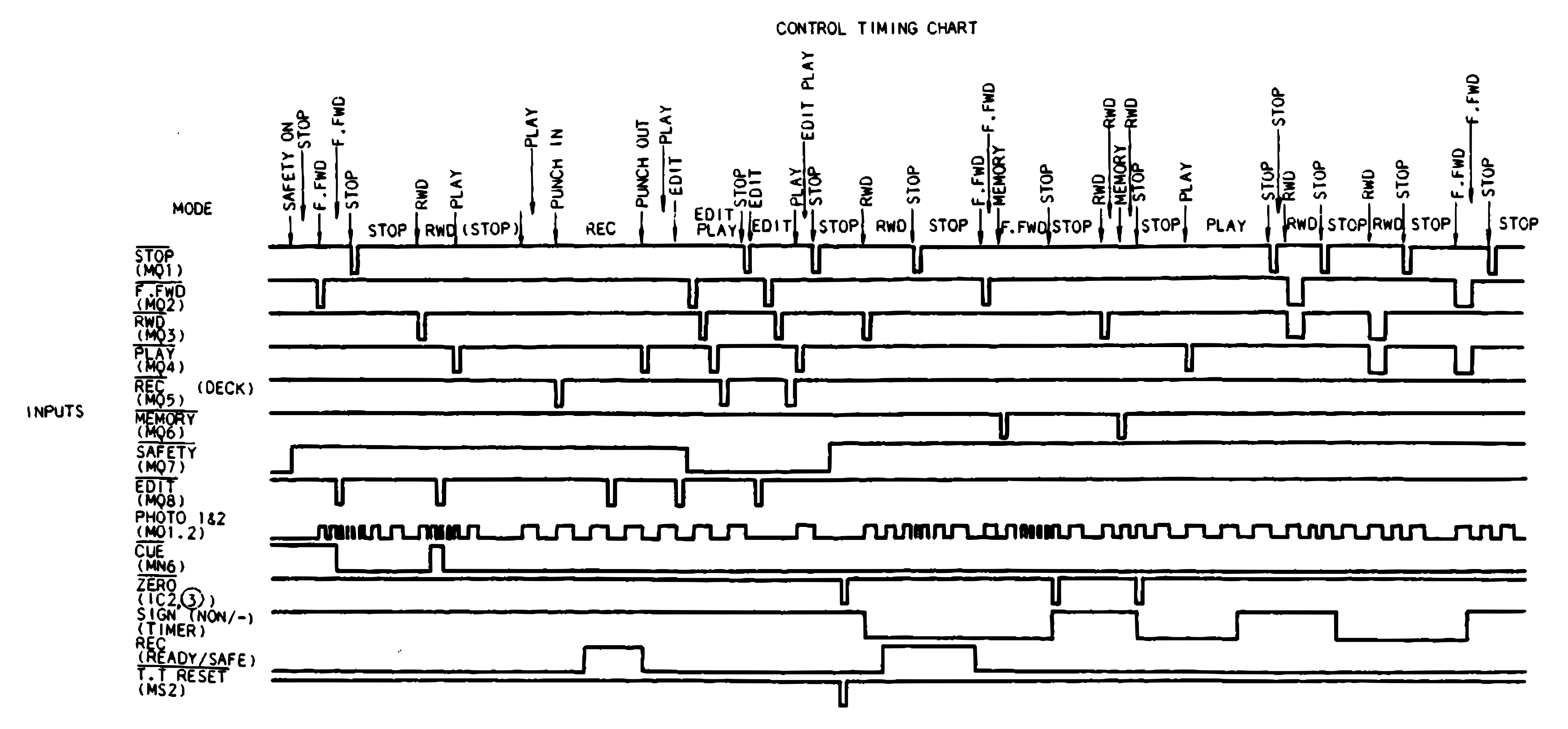 ⤢ zoomThe inputs half of the control timing chart: a MODE row of transport commands above the STOP, F.FWD, RWD, PLAY, REC, MEMORY, SAFETY, EDIT, PHOTO 1&2, CUE, ZERO, SIGN, REC READY/SAFE and T.T RESET input waveforms.
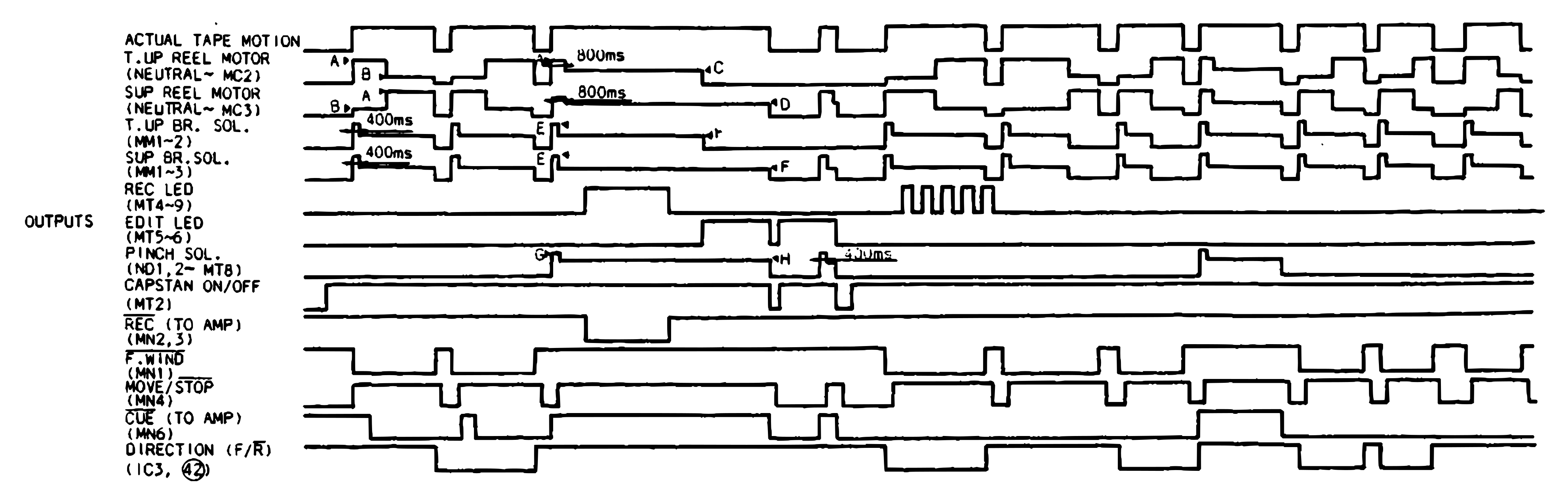 ⤢ zoomThe outputs half of the control timing chart: actual tape motion above the take-up and supply reel motor, take-up and supply brake solenoid, REC LED, EDIT LED, pinch solenoid, capstan on/off, REC to amp, F.WIND, MOVE/STOP, CUE to amp and direction waveforms, with points A to H marking the supply voltages tabled below and 800 ms and 400 ms delays.
*REEL SUPPLY VOLTAGE (AC)
| REEL SIZE | LARGE | SMALL |
|---|---|---|
| A | 100V | 80V |
| B | 28V | 22V |
| C | 60V | 50V |
| D | 43V | 35V |
**SOLENIOD SUPPLY VOLTAGE (DC)
| VOLTAGE | |
|---|---|
| E | 27V |
| F | 12V |
| G | 22V |
| H | 17V |
Figure 6-7 Control Timing Chart
6-6 RECORDING PROCESS TIMING CHART↑ TOP
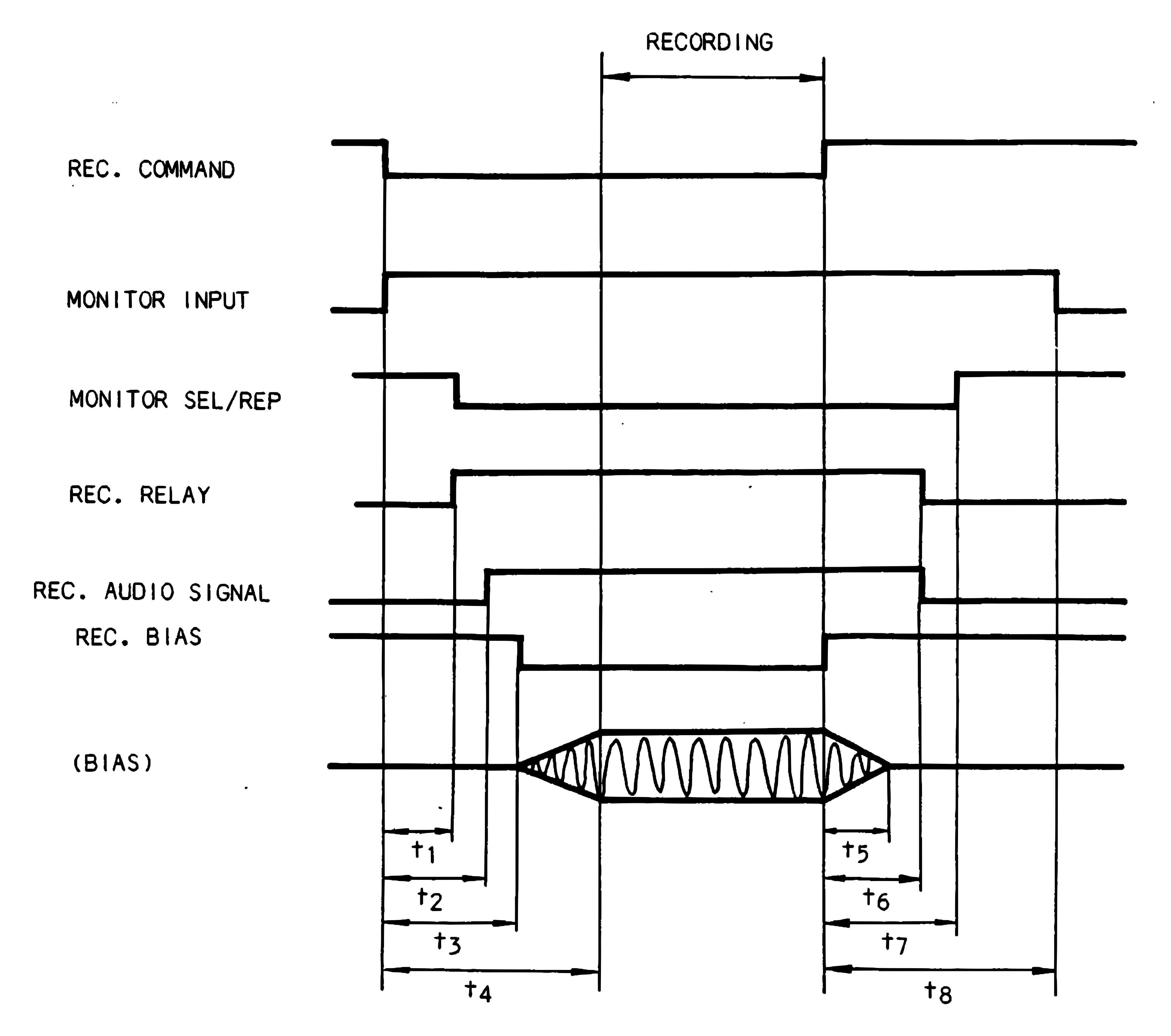 ⤢ zoomThe recording process timing chart, plotting the REC. COMMAND, MONITOR INPUT, MONITOR SEL/REP, REC. RELAY, REC. AUDIO SIGNAL, REC. BIAS and BIAS waveforms around the recording interval, with delay intervals t1 through t8 marked at the transitions into and out of recording.
| t1: | MONITOR SEL/REP OFF & REC. RELAY ON operate time | ; 36 msec |
| t2: | REC. AUDIO SIGNAL start delay time | ; 54 msec |
| t3: | REC. BIAS start delay time | ; 72 msec |
| t4: | REC. BIAS rise time | ;117 msec |
| t5: | REC. BIAS fall time | ; 40 msec |
| t6: | REC. RELAY & REC. AUDIO SIGNAL release delay time | ; 54 msec |
| t7: | MONITOR SEL/REP ON operate time | ; 72 msec |
| t8: | MONITOR INPUT OFF operate time | ; 126 msec |
Figure 6-8 Recording Process Timing Chart