BQ-II Instruction and Maintenance Manual — Digital Edition · Part 5 · PDF pages 40-49
Routine Maintenance and Conversion Information
5-1 ROUTINE MAINTENANCE↑ TOP
It is important that routine maintenance be performed at the recommended intervals.
Exterior cleaning and demagnetization should be performed after every eight hours of operation, and the interior of the transport should be cleaned once a month.
Lubrication should be performed after 1,000 hours of operation or after 6 months, whichever comes first.
5-1-(1) CLEANING↑ TOP
Oxide particles from the magnetic tape tend to collect on components in the tape path and degrade the performance of the recorder.
To clean the head assembly, proceed as follows:
(1) Disconnect the power cable from the power supply.
(2) Lift the head cover as shown in Figure 5-1.
CAUTION
WHEN CLEANING THE HEADS, USE THE RECOMMENDED SOLVENT (HEAD CLEANER) ONLY TO AVOID
DAMAGING THE HEADS.
KEEP THE HEAD CLEANER OFF PLASTIC FINISHES AND THE CAPSTAN PINCH ROLLER.
DO NOT USE METAL TOOLS THAT COULD SCRATCH THE HEADS.
(3) Clean each head thoroughly with a cotton-tipped applicator (Q tip) dampened with head cleaner.
(4) Use isopropyl alcohol to clean all tape-guiding components the capstan shaft, and the capstan pinch roller.
CAUTION
- DO NOT USE A HEAD CLEANER ON THE CAPSTAN PINCH ROLLER, SINCE THIS WILL CAUSE DAMAGE AND TAPE SLIP.
- BEFORE REMOVING THE REAR COVER, THE PLUG MUST BE DISCONNECTED FROM THE POWER SUPPLY TO AVOID AN ELECTRIC SHOCK.
(5) Remove the rear cover of the recorder by removing 10 screws, then open the Control P.C. Board Ass'y by removing both sides 6 screws. (Refer to Figure 5-7.)
(6) Use a vacuum cleaner and a small brush to remove all dust or contamination from the interior of the transport. If necessary lightly moisten brush with isopropyl alcohol to clean parts.
(7) Install the rear cover and the Control P.C. Board Ass'y.
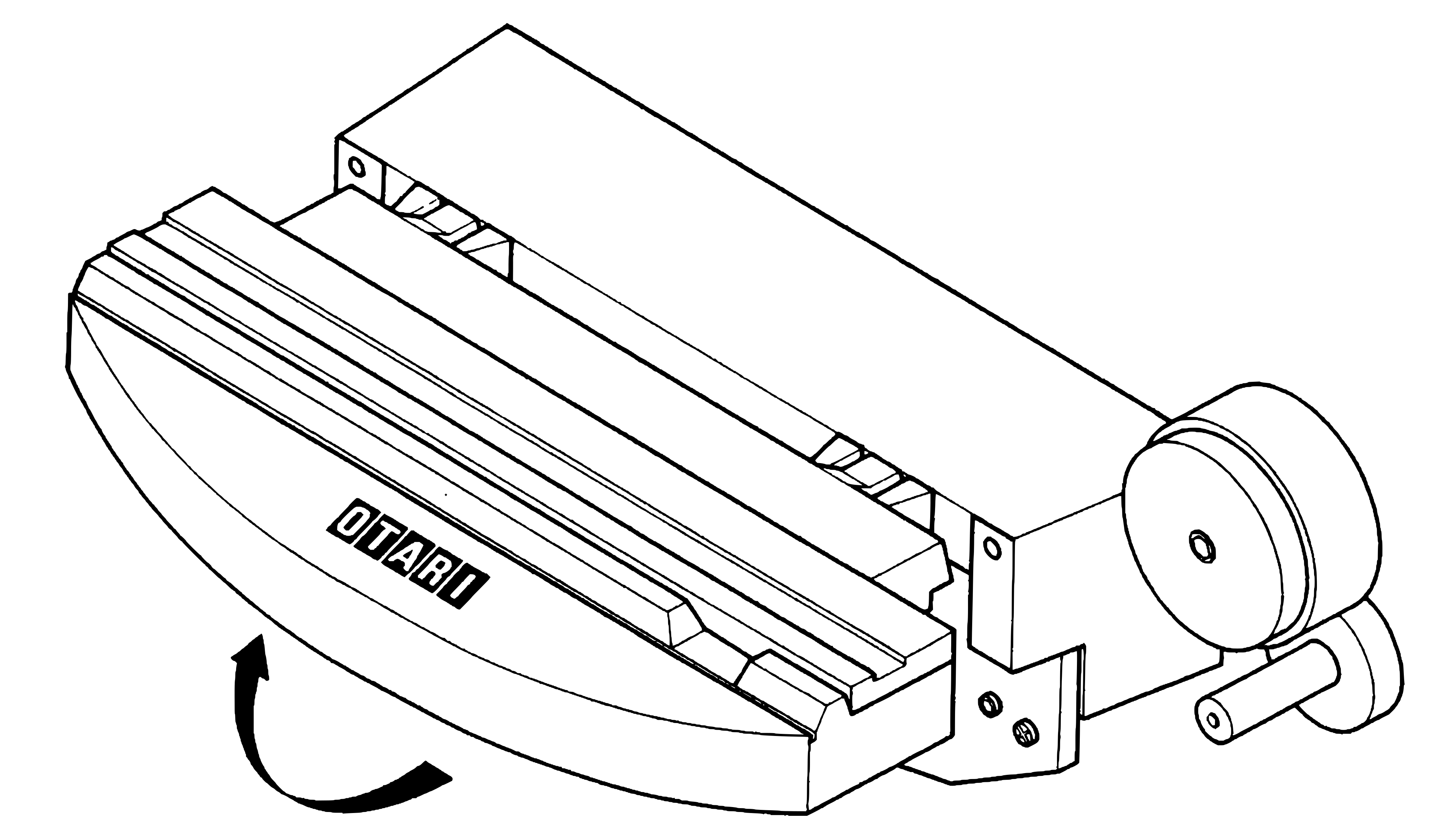 ⤢ zoomThe head housing with its cover, which carries the OTARI logo, and a curved arrow at the cover's front edge showing it being lifted up and back off the heads.
Figure 5-1 Lifting the Head Cover
5-1-(2) DEMAGNETIZING↑ TOP
The heads and tape guiding components in the tape path should be demagnetized after every eight hours of operation.
These components can acquire permanent magnetization that increases noise and distortion, and partially erases high frequencies on recorded tapes.
Use a hand-held head demagnetizer to demagnetize all components in the tape path as follows:
(1) Turn equipment power off and move any recorded tape near the transport away (tape could be partially erased by the demagnetizer) •
(2) Lift the head cover as shown in Figure 5-1.
(3) Cover the demagnetizer tips with an adhesive tape to prevent scratching the head stacks.
(4) With the demagnetizer at least three feet away from the transport, connect the demagnetizer to a power source.
(5) Slowly move the demagnetizer tips close to the head, lightly touch the
demagnetizer tips to the face of one head stack and slowly move the tips up and
down at the entire face of the stack several times.
Then slowly withdraw the demagnetizer as shown in Figure 5-2.
(6) Repeat step 5 for each head stack.
(7) Repeat the motions in step 5 for each guide and other metallic parts in the tape path.
(8) Slowly move the demagnetizer at least three feet away from the transport and then disconnect the power from the demagnetizer.
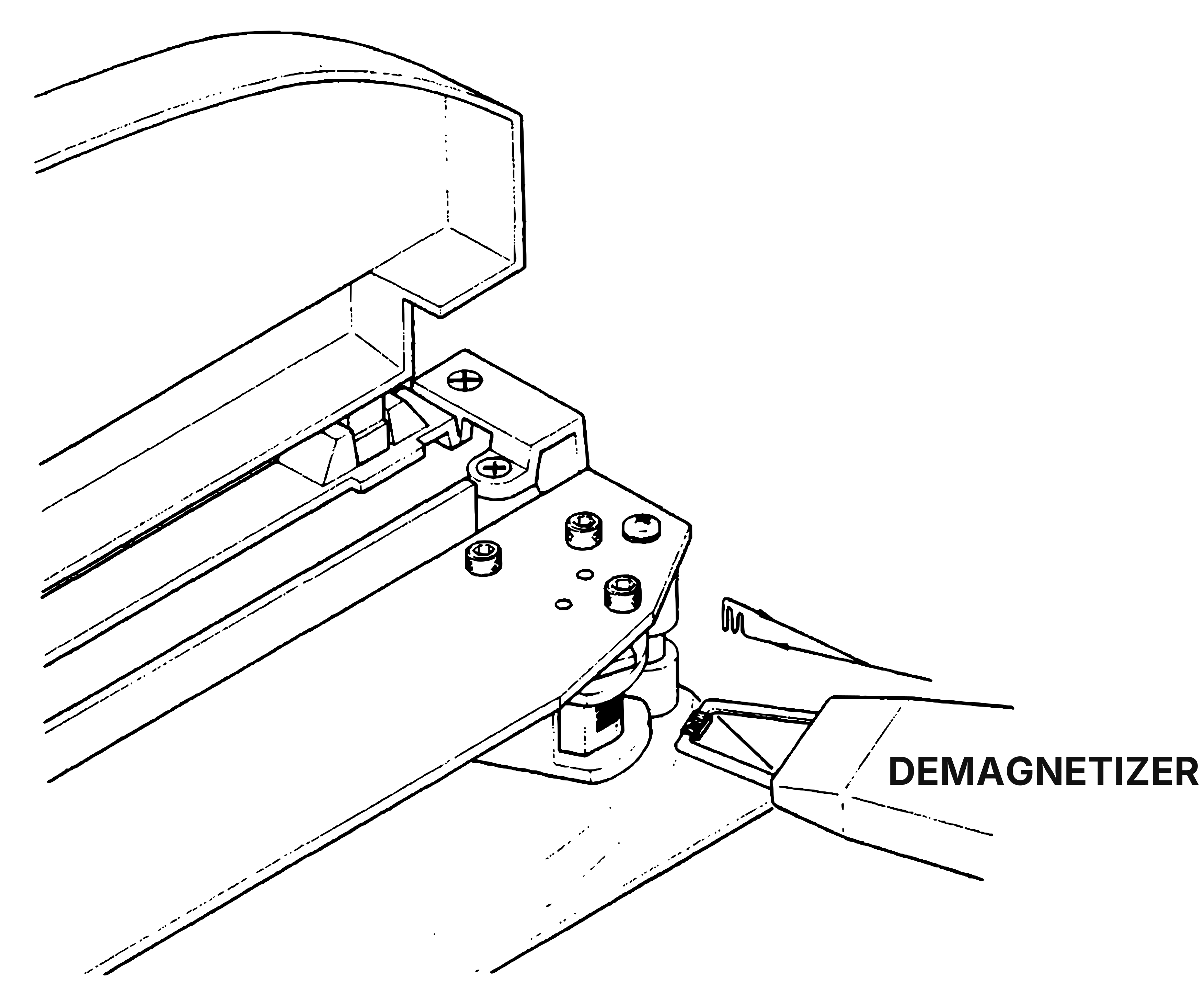 ⤢ zoomThe head assembly with its cover raised and a demagnetizer, labelled DEMAGNETIZER, held with its tips against the face of a head stack.
Figure 5-2 Demagnetizing
5-1-(3) LUBRICATION↑ TOP
The only components requiring lubrication are the capstan sleeve bearing and the capstan
pinch roller sleeve bearing.
Refer to Figure 5-3 and proceed as follows:
CAUTION
- DO NOT USE ANY OIL EXCEPT ANDEROL #456 FOR LUBRICATION.
- BE CERTAIN TO CLEAN THE CAPSTAN SHAFT THOROUGHLY. LUBRICATIONG OIL
COULD RUIN THE CAPSTAN PINCH ROLLER AND MAGNETIC TAPE.
CLEAN THE CAPSTAN (AND PINCH ROLLER) WITH ISOPROPYL ALCOHOL AFTER LUBRICATION.
For the pinch roller sleeve bearing and the capstan sleeve bearing:
(1) Remove the pinch roller cap by removing the screw on it.
(2) Remove the pinch roller from the pinch roller shaft.
Note that there is one polyslider washer on each side of the pinch roller
bearing .
(3) Remove two hex socket head screws on the Head Housing Cover.
Remove the head front escutcheon by removing the two screws on it and remove the
head rear escutcheon by removing the three screws on it.
Turn the Dust Cap counterclockwise and pull off from the capstan.
(4) Apply 2 or 3 drops of oil to this felt collar.
Do not over lubricate.
(5) Apply a few drops of oil to the pinch roller sleeve bearing.
(6) Wipe off any excess oil and install the dust cap, head front escutcheon, head rear escutcheon, and pinch roller cap in the reverse order.
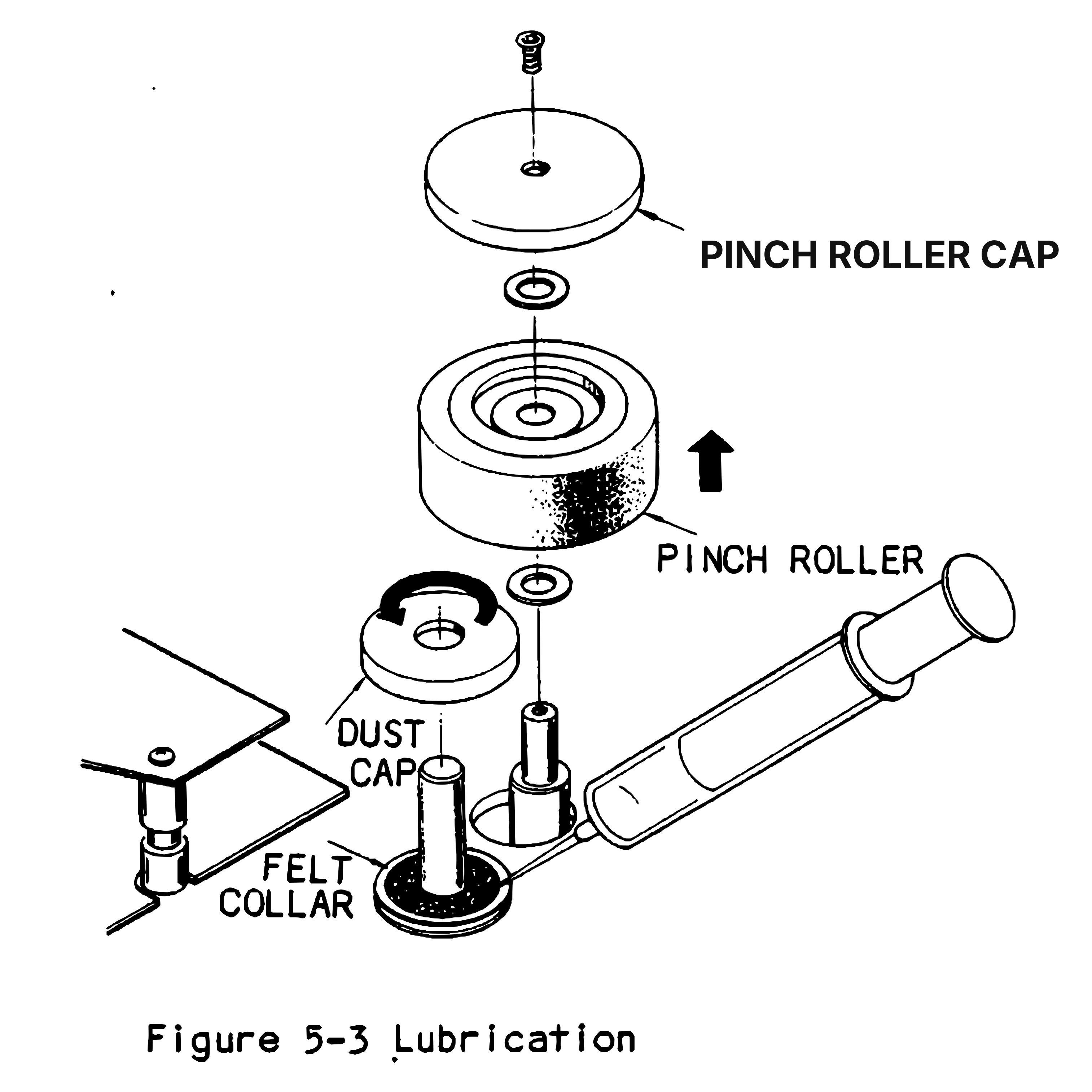 ⤢ zoomFigure 5-3 Lubrication: An exploded view of the pinch roller assembly, with the screw, pinch roller cap, washers and pinch roller lifted off their shaft, the dust cap turned off the capstan, and an oiler pointed at the felt collar round the capstan's base.
5-2 TAPE REPLACEMENT↑ TOP
The MX-5050 BQTI is set at the factory for Scotch #226 Recording Tape.If another tape
is to be used, the following adjustment may be required for optimum tape performance.
Refer to Section 7.
Required adjustments are:
(1) The record bias adjustment.
(2) The record level adjustment.
5-3 EQUALIZER CHANGE↑ TOP
The equalizer between the NAB or the IEC can be changed by replacing the REC/REPRODUCE
Amplifier P.C. Board Ass'y. However, a fine equalizer adjustment and a record level
set are required.
Refer to Section 7 to aid the fine adjustment.
Table 5-1 Record level
| Reference Fluxivity | Relative level | Test Tape | Recording tape to be used |
|---|---|---|---|
| 185 nWb/m* | 0 dB | Ampex Operating level | Scotch 177, Ampex 641 |
| 250 nWb/m* | +2.6 dB | MRL NAB standard | Scotch 206,207,226,250 Ampex 406,407,456 |
| 320 nWb/m** | +3.8 dB | BASF or MRL IEC Standard | IEC Equalization |
* Short circuit flux.
** Open circuit flux.
5-4 LINE VOLTAGE CONVERSION↑ TOP
The line voltage is converted by resoldering the wiring on the voltage selection terminal, Proceed as follows:
(1) Remove the rear cover by removing 10 screws. (Refer to Figure 6-1)
(2) Resolder the lead wire of the voltage selection terminal located on the supply reel Ass'y to the desired voltage terminal marked as shown in Figure 5-4.
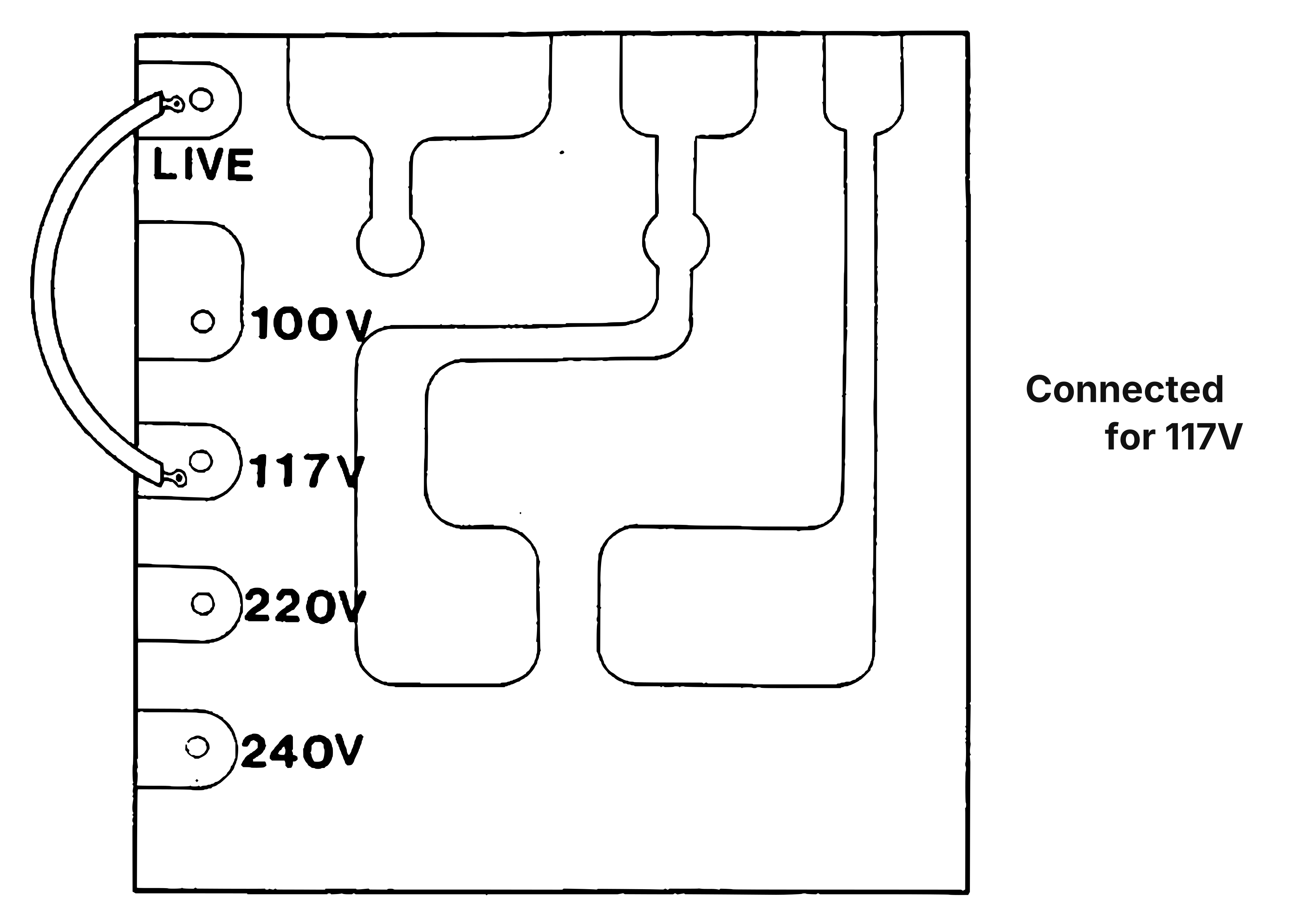 ⤢ zoomThe voltage selection terminal board, with tabs marked LIVE, 100V, 117V, 220V and 240V and a jumper wire from LIVE to the 117V tab, noted as connected for 117V.
Figure 5-4 Voltage Selection Terminal
5-5 FUSE REPLACEMENT↑ TOP
If a fuse is blown, it is important that the possible cause is checked before replacing the fuse.
CAUTION
FOR CONTINUED PROTECTION AGAINST FIRE HAZARD, REPLACE ONLY WITH THE SAME TYPE OF FUSE.
BEFORE REPLACING THE FUSE, REMOVE THE POWER CORD FROM THE POWER SOURCE.
Information concerning the seven fuses can be found in Table 5-2 . For the main power fuse (FS801), proceed as follows:
(1) Remove the board on the left side by removing four hex socket head screws.
(2) Replace the main power fuse (FS801) on the power switch P.C. Board.
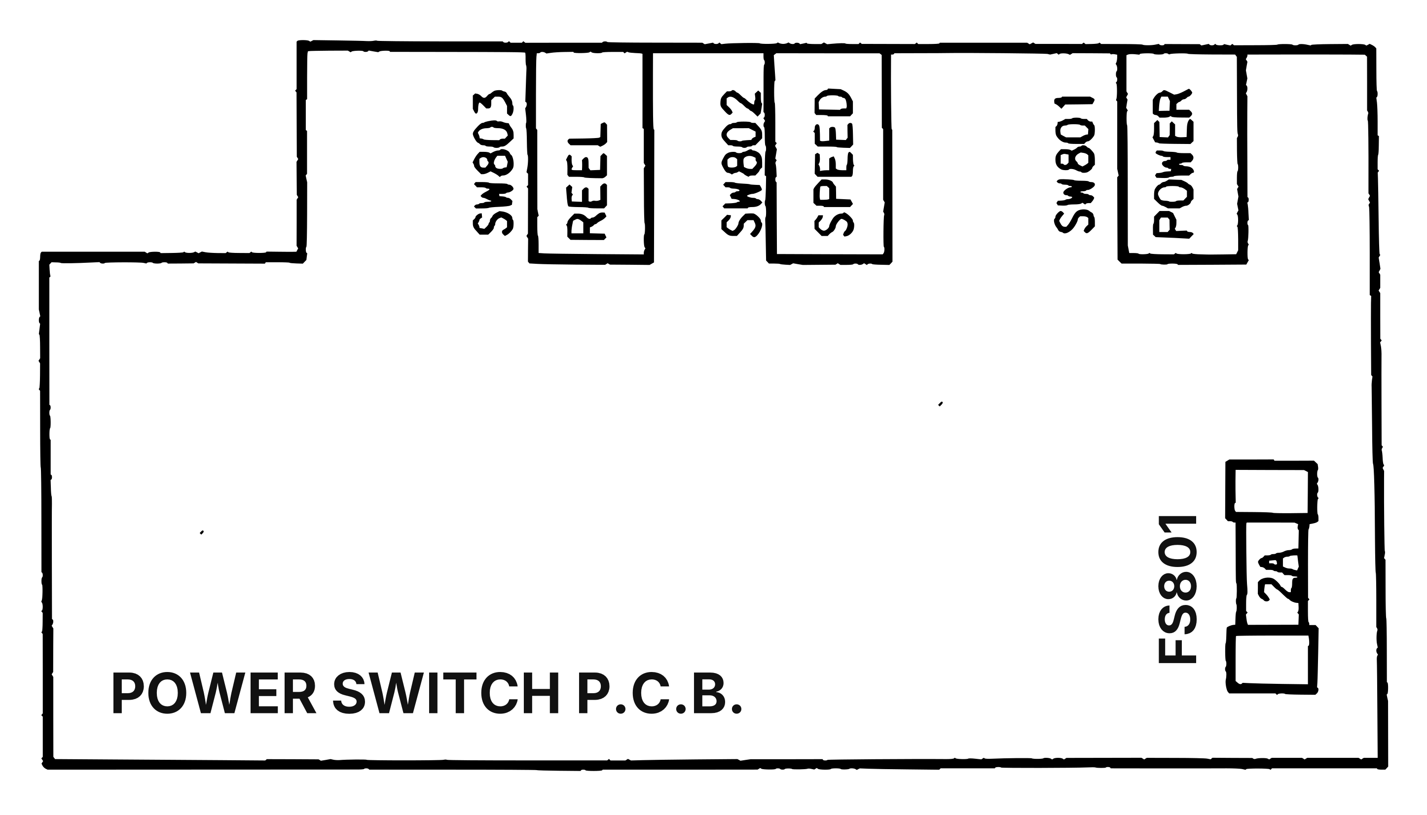 ⤢ zoomThe power switch P.C.B. outline, with the REEL, SPEED and POWER switches SW803, SW802 and SW801 along its top edge and the 2A main power fuse FS801 at its right-hand end.
Figure 5-5 Main Power Fuse Location
For other fuses (F1 - F6), proceed as follows:
(1) Remove the rear cover by removing ten cross-recessed screws.
(2) Remove six cross-recessed screws marked "OPEN" on the Control P.C. Board.
(3) Pull the Control P.C. Board down, and replace the blown fuse.
| Reference | Rating | Otari part | |||||
|---|---|---|---|---|---|---|---|
| number | Current | voltage | size(inch,mm) | carry | blow | number | Used for |
| FS801 | 2A | 250V | 1/4x1 1/4 inch 6.3x32mm | 110~ | 135% In 1 hour | FH7E020 | Primary Circuit |
| F1 | 1A | " | 13/64x45/65 inch 5x20mm | " | " | FH7F010 | VU Meter Lamps |
| F2 | 2A | " | " | " | " | FH7F020 | DC Servo Cap. Motor Driver |
| F3 | " | " | " | " | " | " | Pinch roller Solenoid, Relays, and DC Servo Cap. Motor Control |
| F4 | " | " | " | " | " | " | 2:1 5 V Amplifier |
| F5 | " | " | " | " | " | " | " |
| F6 | " | " | " | " | " | " | Brake Solenoids, +5V Transport Control LEDs |
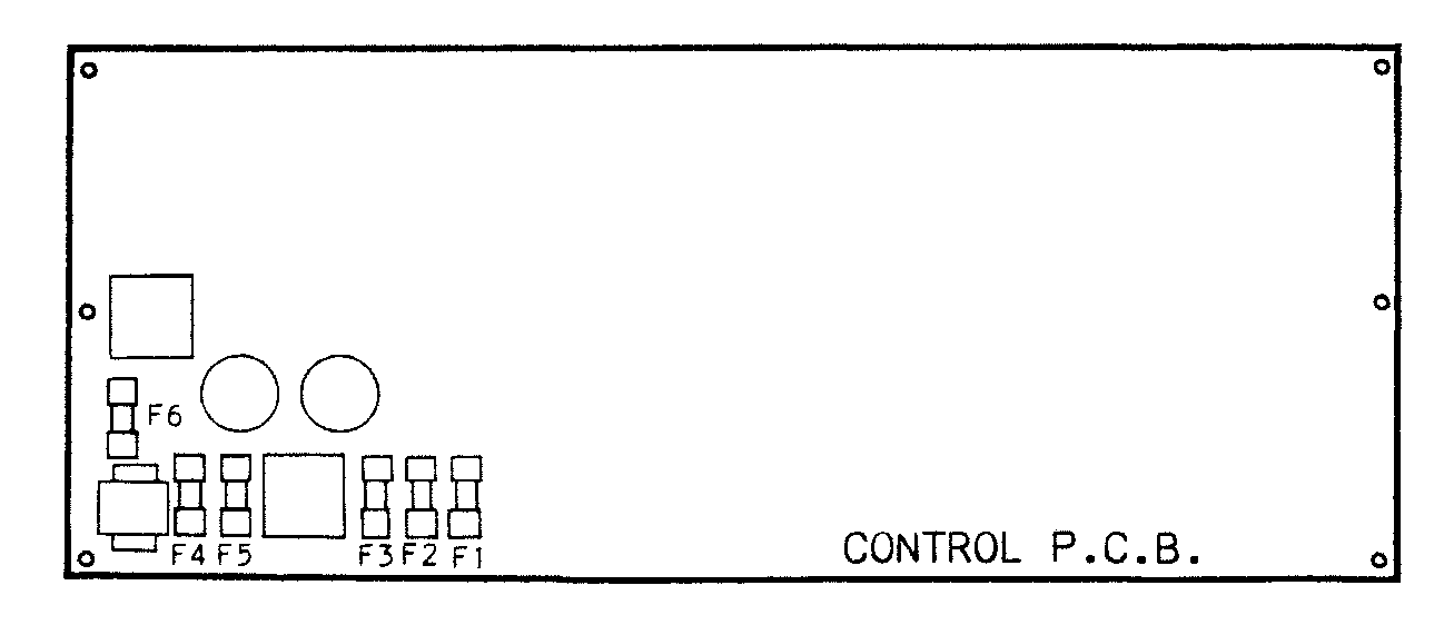 ⤢ zoomThe control P.C.B. outline, labelled CONTROL P.C.B., with fuses F1 to F6 grouped at its lower left-hand corner.
Figure 5-6 Internal Fuse Location
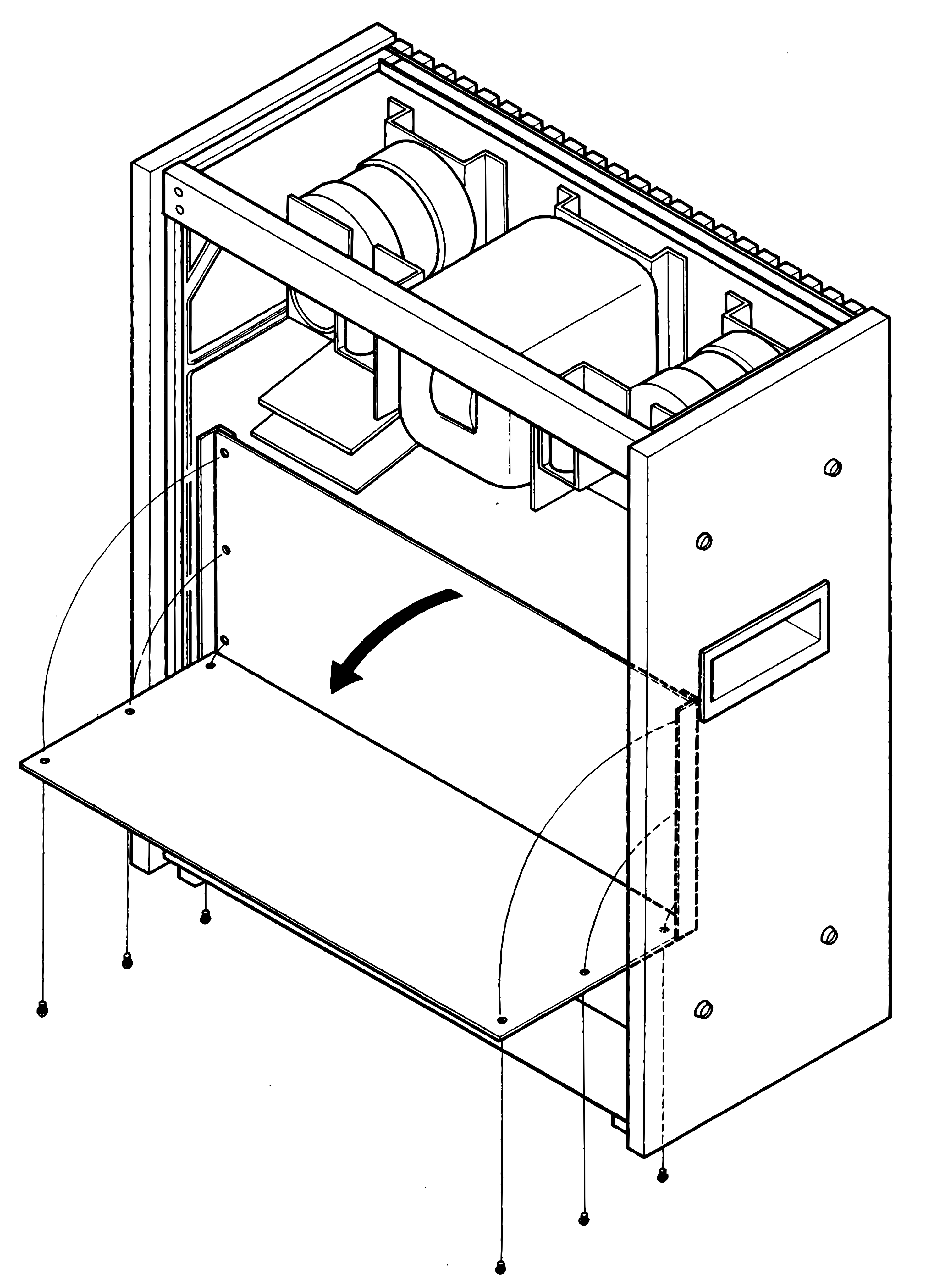 ⤢ zoomThe recorder's chassis seen from the rear with the cover off, the control P.C. board folded down on its lower hinge edge as a curved arrow shows, and its six fixing screws drawn below.
Figure 5-7 Rotating Control P.C.B.