2026-06-27
No dummy plug — no problem!
The transport won't move because the remote socket needs a shorting plug that never came with the deck. Fine. Let's build one.
Reading the pinout
Everything you need is at the top of the tape transport schematic (TD-5050). In the upper right corner you can see square boxes labeled 1 to 12 — these correspond to the REMOTE jack at the rear of the unit. To map them onto the plug: the upper left is pin 1, to the right is pin 2, right again is pin 3, and the start of row 2 is pin 4 — three across, four rows down.
Which pin is pin 1?
Three things keep you from wiring a mirror image:
 The remote socket up close: vertical slots in the top two rows, horizontal slots in the bottom two — the keying that makes the plug fit only one way
- The connector is keyed. Look closely at the socket: the slots in the top two rows are vertical, and the bottom two rows are horizontal. The plug's blades match that pattern, so it physically cannot go in rotated or upside down — a plug wired to the right terminals can't be inserted wrong.
- The plugs number their terminals. On an original Cinch-pattern plug, each solder terminal has its pin number molded into the body beside it — you can make them out beside the terminals in the photos below. Wire to the numbers, not to remembered positions.
- Know the mirror trap. The wiring side of any plug is the mirror image of its mating face — count pins on the front, flip it over to solder, and left has become right. The molded numbers are the antidote: if you're wiring by them, you never have to count at all.
The experimental version
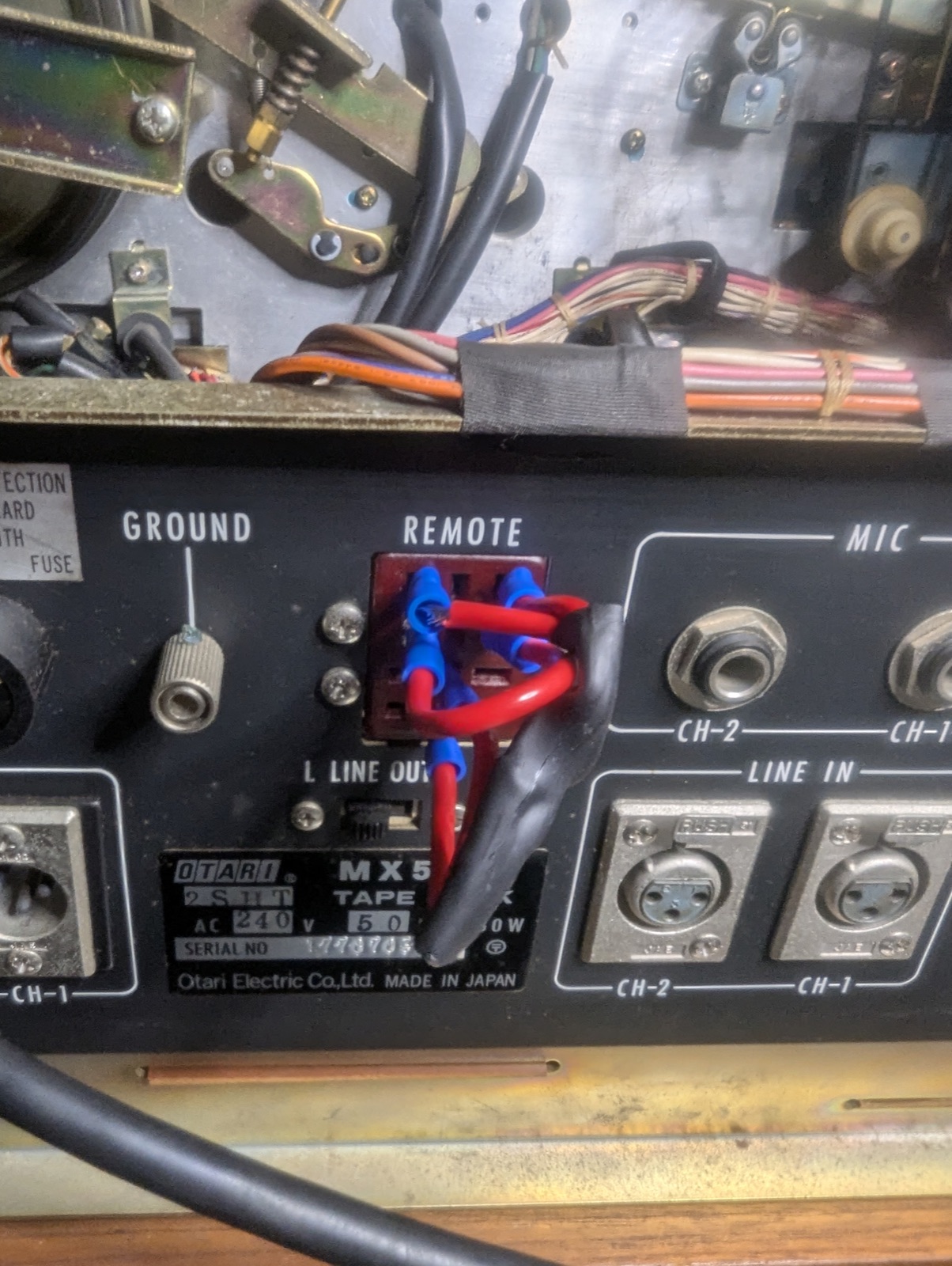 Experimental dummy plug — automotive crimp jumpers in the MX-5050 remote jack
This photo was my experimental attempt. I had a case of automotive ends, and one was a blade that would fit inside the socket once I built up its width with a little solder. So I made a Frankenstein jumper that connects pins 1 to 3 to 8 to 11, and a second jumper that connects 4 and 6.
The proper part
The original connector is what's called a Cinch Jones plug — I was able to find an old one on eBay and build the tidy version: the same 1–3–8–11 and 4–6 jumpers, soldered to the numbered terminals inside a proper plug body.
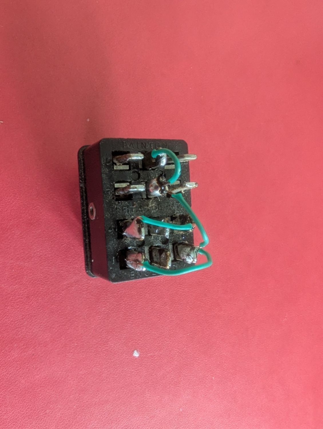 Old Cinch-pattern plug rewired as a dummy plug: green jumper wires soldered across the numbered terminals
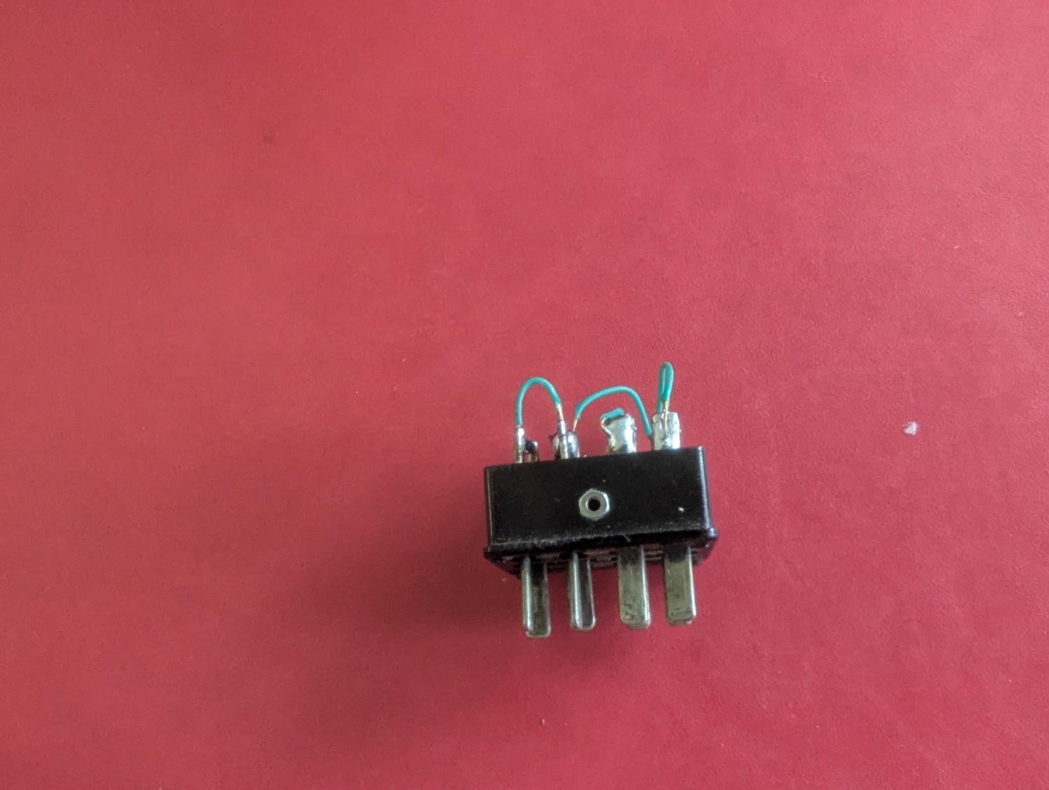 The rewired plug from above, jumper loops arcing over the plug body
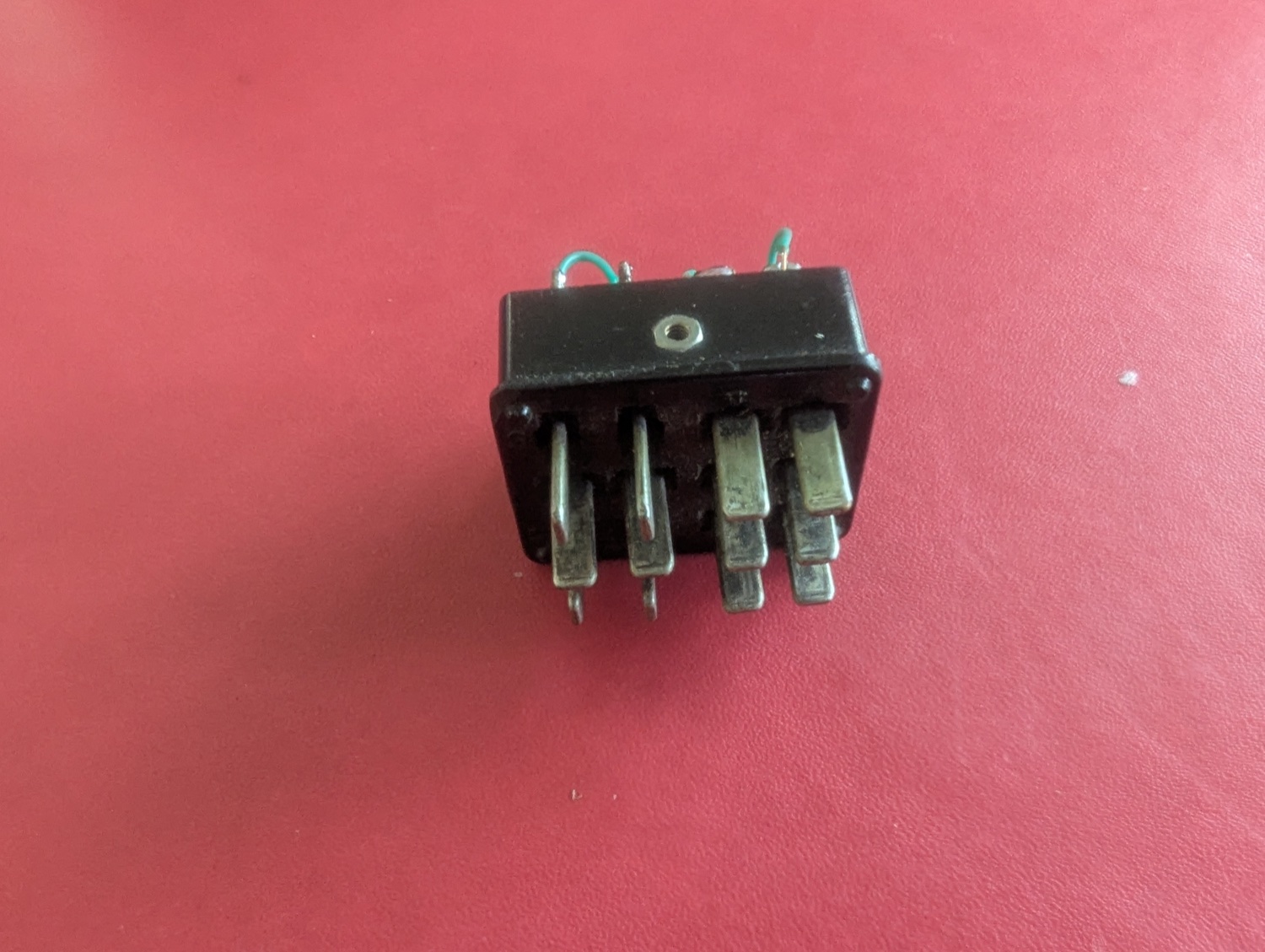 Pin side of the rewired plug — the blade pins that seat into the remote socket
There's also a modern replacement available new from Mouser: 538-13121. Mine has arrived, and it's the real thing — the same Cinch-Jones pattern the deck was built around, right down to the pin numbers molded into the bakelite:
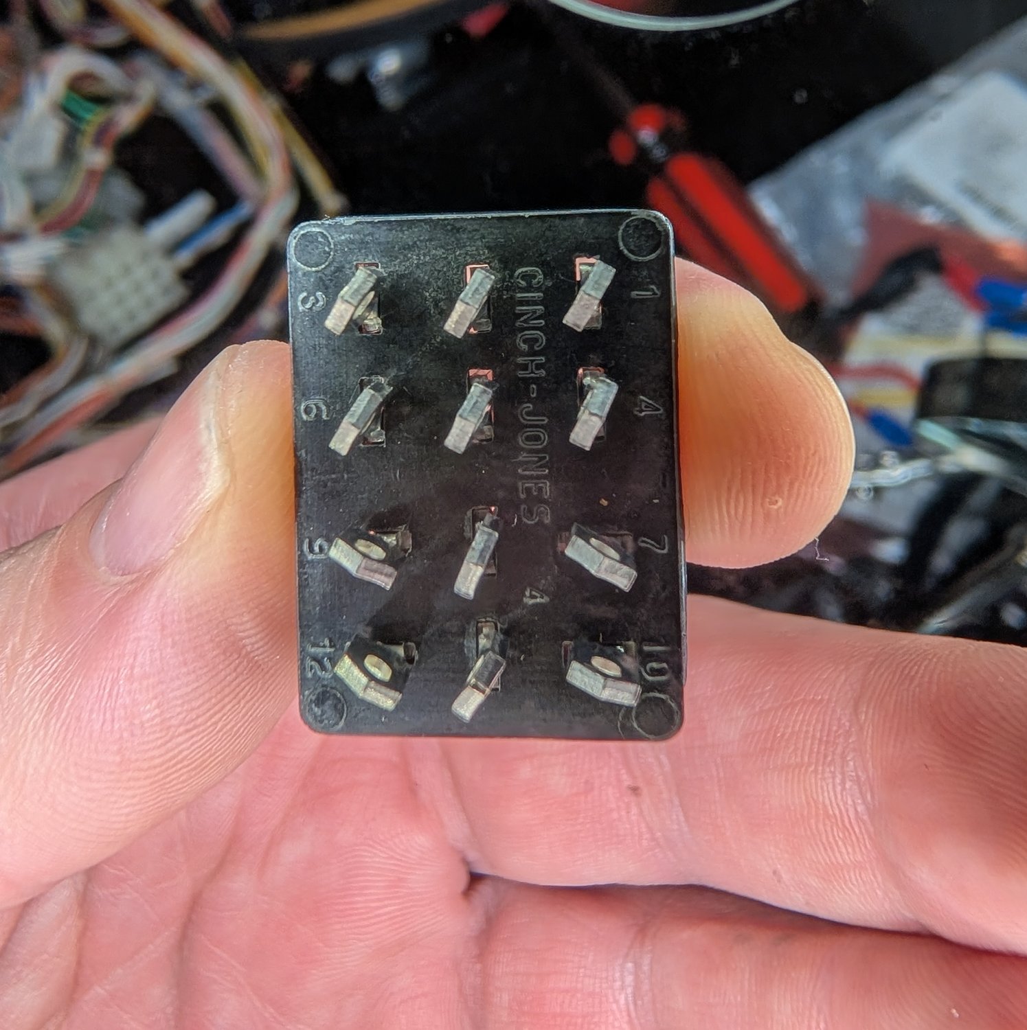 The modern plug's mating face: CINCH-JONES molded down the middle, pin numbers 1, 4, 7, 10 down one edge and 3, 6, 9, 12 down the other, with the keyed blades — vertical in the top two rows, horizontal in the bottom two
The keying and the numbering are unchanged: wire the same 1–3–8–11 and 4–6 jumpers to the numbered terminals, close the hood over it, and you have a brand-new dummy plug.
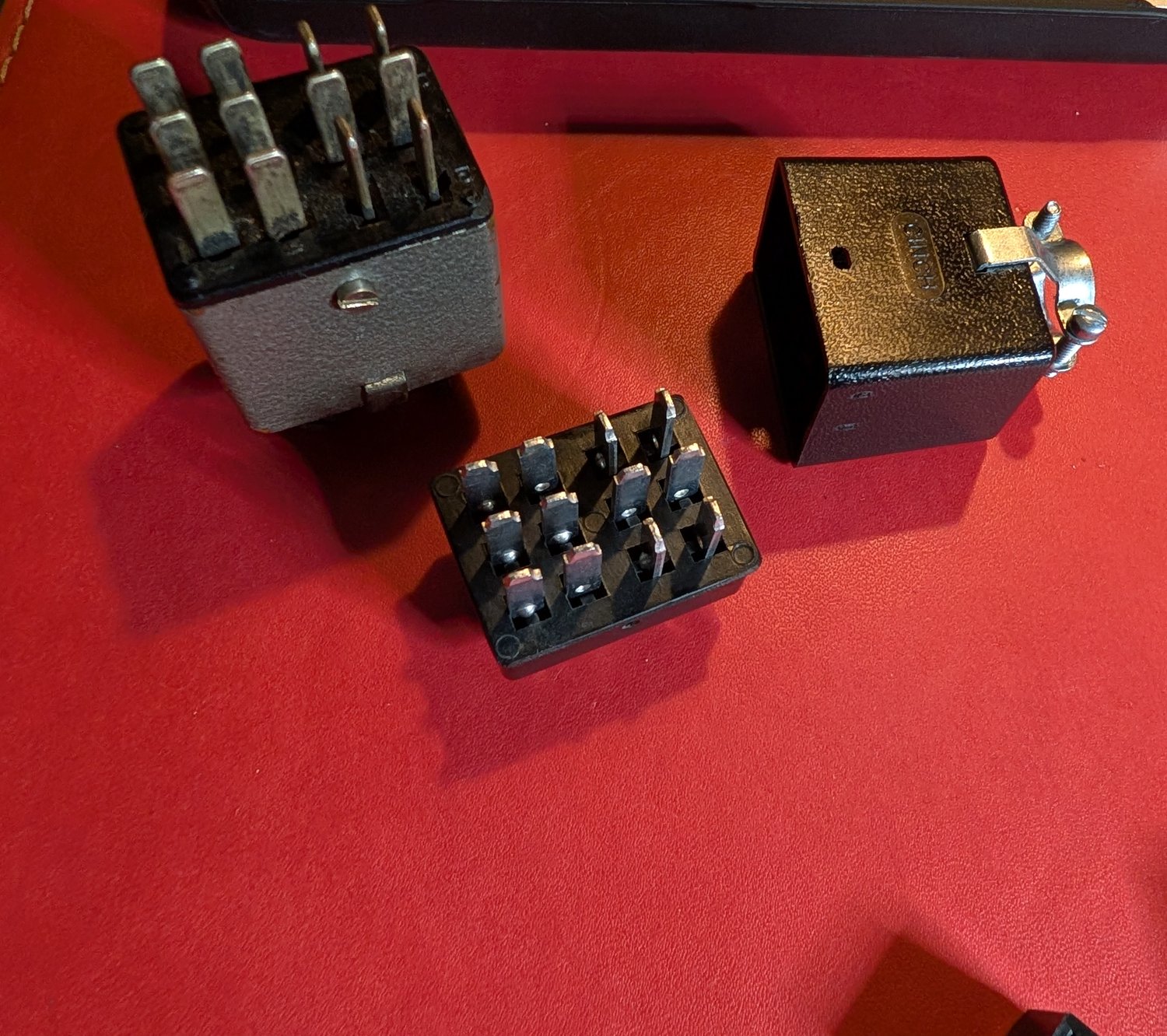 Old and new: the vintage plug in its grey metal hood, the new plug body with its solder terminals facing up, and the new black hood with cable clamp
The original, hiding in plain sight
Until now the original plug was something I'd only inferred from the schematic — my deck arrived without one. But here it is, still in place on another first-generation deck:
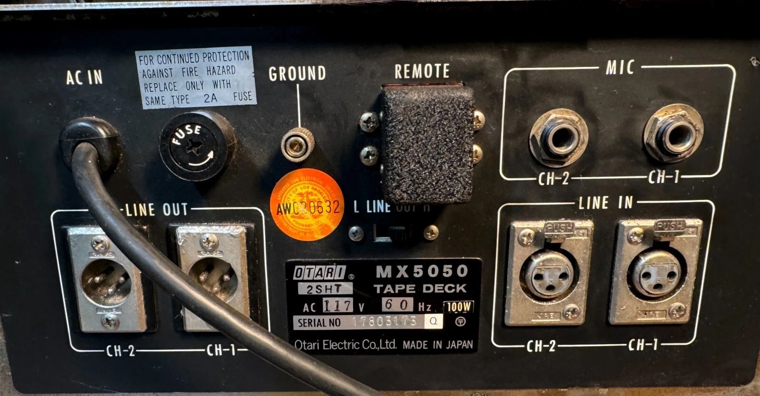 The factory dummy plug on another first-generation deck: a black hooded plug seated in the REMOTE socket, no cable, finished in the same crinkle black as the rear panel
A hooded Cinch plug with no cable coming out of it, sitting in the REMOTE socket, finished in the same crinkle black as the panel itself — which is exactly why it's so easy to overlook, and probably why so many of them have quietly gone missing.
The period press backs this up — here's the rear panel from the interior view (Fig. 2) in the April 1976 Audio review:
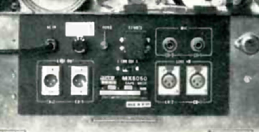 The rear panel in the April 1976 Audio review's interior view: the same black block seated in the REMOTE position of the review machine
The same black block, seated in the REMOTE position of the review machine. These decks left the factory with the socket already plugged — mine lost its plug somewhere in its first fifty years.
The satisfying footnote: the new hood is black crinkle-finish too. With the jumpers soldered inside and the hood closed up, the modern part is all but indistinguishable from what Otari shipped in 1976.
If your "broken" MX-5050 won't move
Mine arrived with no plug at all — that was the entire fault. The transport control runs through the remote socket, and with nothing closing the circuit the machine looks dead: no motion, no obvious fault, nothing on the meters. If you've just bought an original MX-5050 that "doesn't work", check this socket first — before you open anything.