2026-07-17
The playback-first recap: a bench guide
The capacitor choices are settled; this is the order of work. The goal for now is not a full restoration — it is playback, because playback is the half of the machine that will eventually carry my father's tapes. And playback only touches two of the three audio boards:
REPLAY HEAD → [ PA-286A (PM917A) · rep EQ amp ] → REPLAY VR → [ PA-285 (PM-680-1) · line out ] → LINE OUT / PHONES
Walk this chain interactively — with the factory's own levels — on Inside the audio path.
PA-287A (PM918A) — mic and line input, sel-rep — sits entirely outside that chain, and so do the record amplifier and the bias oscillator on PA-286A. They can all wait. What cannot wait is the pair of 1977 tantalums sitting directly on the replay-head input: tantalums fail leaky and then they fail short, and a short there puts DC straight through the head. That is why session one is the replay half of PA-286A and nothing else.
Session 1 — the replay electronics
Session 1
PA-286A (PM917A) · replay half only · 15 capacitors
| ☐ | Position | Original | Role | Fit this |
|---|---|---|---|---|
| ☐ ☐ | C51 / C151 | 10 µF/16 tantalum | Replay-head EQ input | UKL 10 µF/100 V — the two best-measured |
| ☐ ☐ | C73 / C173 | 10 µF/16 tantalum | EQ feedback | UKL 10 µF/100 V |
| ☐ ☐ | C53 / C153 | 47 µF/16 | Emitter bypass | Vishay 013 RLC 47 µF/50 V |
| ☐ ☐ | C56 / C156 | 10 µF/35 | Interstage | UKL 10 µF/100 V |
| ☐ ☐ | C57 / C157 | 1 µF/50 | Output → replay VR | Nichicon UKL 1 µF/100 V |
| ☐ | C301 | 1 µF/50 | EQ speed switching | Nichicon UKL 1 µF/100 V |
| ☐ ☐ | C58 / C158 | 220 µF/25 | +B rail | Nichicon UKL 220 µF/35 V |
| ☐ ☐ | C31 / C131 | 47 µF/35 | +B rail | Panasonic FS 47 µF/100 V |
Leave alone this session: C23/C123, C24/C124, C25/C125 (record amplifier) and C302–C305 (bias and erase) — none of them run during playback.
Session 2 — the line output
Session 2
PA-285 (PM-680-1) · audio path · 22 capacitors
| ☐ | Position | Original | Role | Fit this |
|---|---|---|---|---|
| ☐ ☐ | C59 / C159 | 10 µF/16 | Input coupling (tape/source) | UKL 10 µF/100 V |
| ☐ ☐ | C61 / C161 | 47 µF/25 | Input filter node | Vishay 013 RLC 47 µF/50 V |
| ☐ ☐ | C62 / C162 | 10 µF/25 | First stage output coupling | UKL 10 µF/100 V |
| ☐ ☐ | C63 / C163 | 10 µF/10 | Emitter / feedback | Rubycon YXM 10 µF/50 V |
| ☐ ☐ | C64 / C164 | 47 µF/35 | Mid-amp decoupling | Vishay 013 RLC 47 µF/50 V |
| ☐ ☐ | C66 / C166 | 10 µF/25 | Interstage coupling | UKL 10 µF/100 V |
| ☐ ☐ | C67 / C167 | 33 µF/25 | Line output coupling → XLR jacks | Rubycon TWL 33 µF/25 V |
| ☐ ☐ | C68 / C168 | 4.7 µF/25 | Into the output pair | Vishay 4.7 µF/63 V |
| ☐ ☐ | C69 / C169 | 1 µF/25 | Output stage coupling | Nichicon UKL 1 µF/100 V |
| ☐ ☐ | C70 / C170 | 1 µF/25 | Output stage coupling | Nichicon UKL 1 µF/100 V |
| ☐ ☐ | C72 / C172 | 10 µF/25 | Phones output coupling (→ headphone transformer) | UKL 10 µF/100 V |
Leave alone this session: C201, C206, C207 — the test oscillator only runs during calibration.
Then the same test again, and playback is done: about 37 capacitors across two sittings, out of the sixty-plus a full recap will eventually touch.
Before any of it: the measuring session
The previous entry originally argued the 10 µF couplings onto audio-grade parts backed by physics; its correction replaced them with guaranteed low-leakage stock — UKL 10 µF/100 V bought deep, Rubycon TWL as the active-production backstop. The bench session survives the correction with a promotion: it is no longer a workaround for a missing guarantee, it is selection among guaranteed parts. It still starts before the soldering iron warms up:
- Measure every coupling candidate. DMM on the microamp range, in series with the cap and a 1 kΩ resistor to tame the inrush, across a bench supply at ~10 V. Two minutes for the dielectric to polarise, then read; discharge through the same resistor before handling. Log each one.
- Rank them. These parts guarantee 0.002CV at rated voltage, so at a tenth of it the healthy ones should read fractions of a microamp; anything that can't beat its own datasheet limit at 10 V goes back in the bag.
- The two best measured parts go to C51 and C151, the replay-head inputs. The next tier fills the remaining couplings; the merely good ones do interstage duty.
The first one out
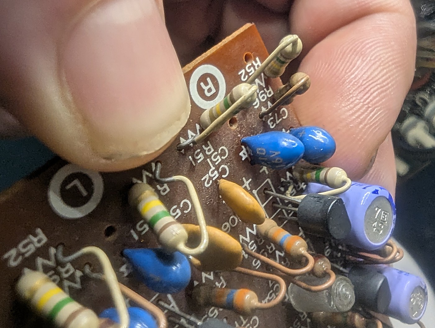 The replay-input corner before desoldering: blue 10 µF/16 V beads on the head inputs, the orange EQ-feedback bead behind them, and the doubled C51/C52 silkscreens between the circled R and L zone marks
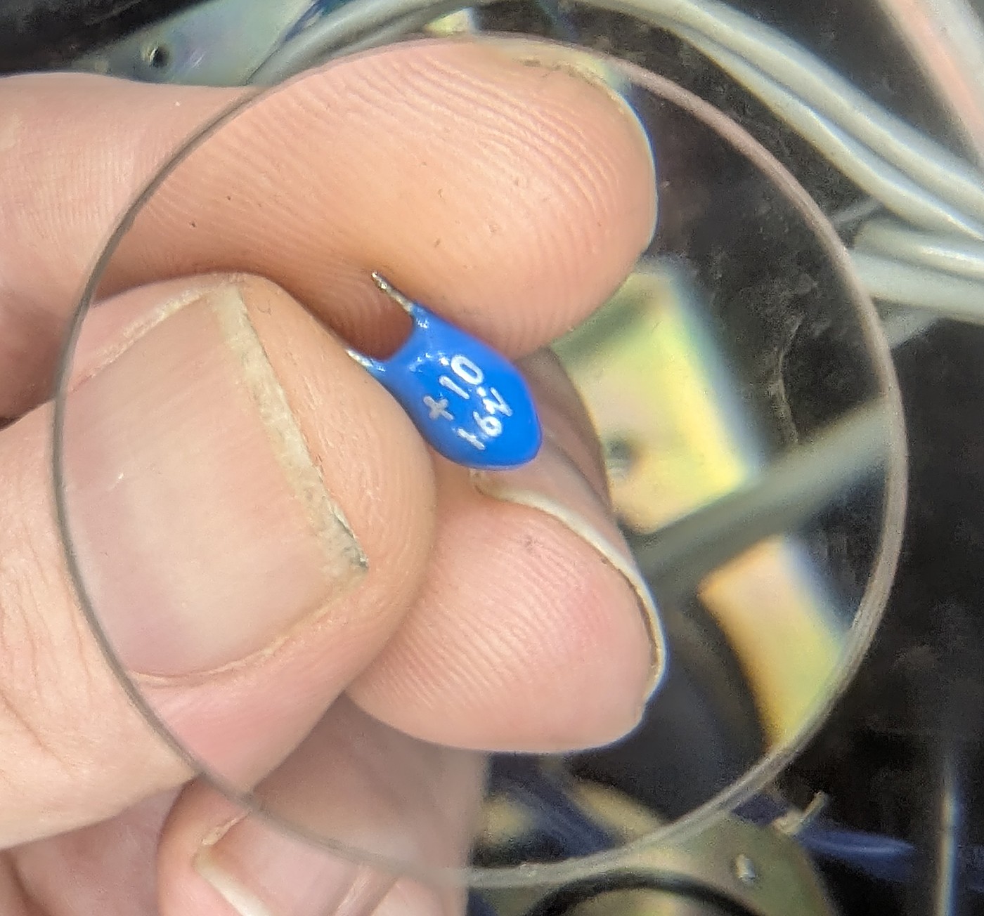 The C51 replay-head tantalum under the loupe, minutes after desoldering: a blue dipped bead marked + 10 16 — 10 µF, 16 volts, and the polarity printed right on the case
C51 is out — the 1977 part that has coupled the replay head since the machine was built, and the reason this recap starts where it does. For a moment at the bench it had me doubting the schematic: the blue epoxy drop looks for all the world like a little film capacitor. The loupe settles it. Film capacitors never wear a +, and a 10 µF film part wouldn't fit in a matchbox. This is the dipped solid tantalum bead the parts list promises, announcing its own polarity, capacitance and voltage in three short lines.
The board had a second double-take queued: the silkscreen prints C51 twice, once per channel — the note above explains the Ⓡ / Ⓛ zone letters that tell the twins apart. Which zone a part came out of goes in the bench log next to its measurement, or the numbers stop meaning anything by the second session.
On the component tester it reads 10.57 µF and 0.83 Ω ESR — inside tolerance on both counts, forty-nine years on. Which is exactly the point worth logging: a component tester works at about a volt and never holds DC across the part, so the one number that condemns an old tantalum — leakage at working voltage — is invisible to it. This part will sit the same two-minute bench test as its replacements, and its reading goes in the log whatever it says. The case for replacing it was never today's capacitance; it was the retirement plan.
Session 1: before and after
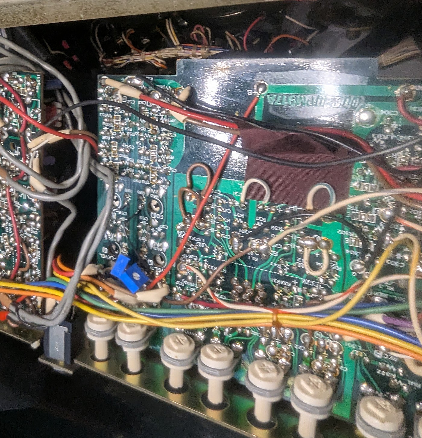 The rec/EQ board flipped solder-side up for the session, still wired into the loom — mirror-printed PM917A silkscreen showing through, mounting screws out, just enough slack to work
First, the working arrangement, because this generation makes you earn it: the first-gen boards have no harness sockets — every wire in that loom is soldered straight to its board terminal. Later machines got plug-in boards; this one got a hundred hard-wired conductors. So the method was: pull the mounting screws, and each board flips over to either side for soldering with everything still connected — the factory left just enough slack in the loom for exactly this. On an ambitious day I'll fit proper harness connectors and make the boards removable the way Otari eventually would; today was not that day, and it didn't need to be.
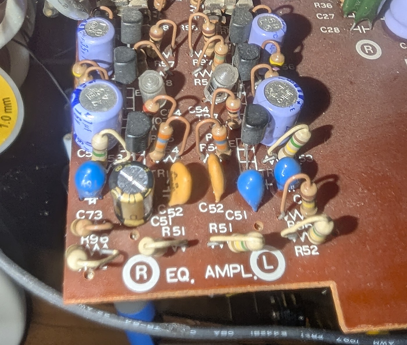 The EQ AMPL zone before: blue and orange tantalum beads among the 1977 electrolytics, the circled R and L zone letters flanking the block
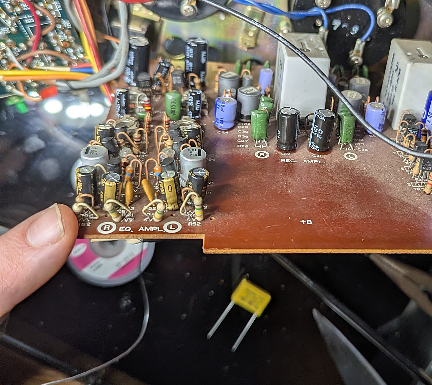 The same zone after session 1: gold 100-volt cans at the head inputs, black-and-gold Nichicons through the interstages, silver Vishay 47 µF cans at the emitter bypasses — the REC AMPL zone beyond still all-original
Session 1 is done — fifteen positions in one sitting, and the machine plays. The low-leakage order was still in transit, so the bench stock carried the day, and the after photo reads like a parts list: the gold cans at the head-input corner are UFW 10 µF/100 V, the audio-grade 100-volt parts the original plan was built around; the black-and-gold KW cans cover the remaining 10 µF couplings; the silver cans marked 50 V/47 µ are the Vishay 013 RLC emitter bypasses; the 1 µF positions and the 220 µF rail caps are UKL from the hoard; and the pair of black 47 µF/100 V Panasonics standing in the REC. AMPL. zone are C31/C131 — physically record-side, electrically the shared +B rail this session owns.
And the confession that keeps this log honest: the measuring session didn't happen. The rig the previous section describes assumes a bench power supply worth trusting, and this bench doesn't have one yet — a steady, known voltage held across the part for two minutes is the whole measurement, and improvising it wasn't worth the uncertainty it would put in the numbers. So every one of those couplings went in on its datasheet and the derating physics alone — including the two positions where this plan swore it wouldn't rest on "typical". The debt is recorded, not forgiven: when the low-leakage order lands, siblings from the fitted lots go through the rig, and C51/C151 get revisited only if those numbers look bad — a second thermal cycle on forty-nine-year-old pads costs more than a spec-sheet upgrade is worth. The old C51's own leakage reading is still owed for the same reason.
Until then the exit path is unchanged: a demagnetizer pass now that the iron is cold, then the full junk-tape run — both channels, both speeds, a complete reel — before session 2 gets a soldering iron anywhere near the line-out board.
Session 2: the line-out board
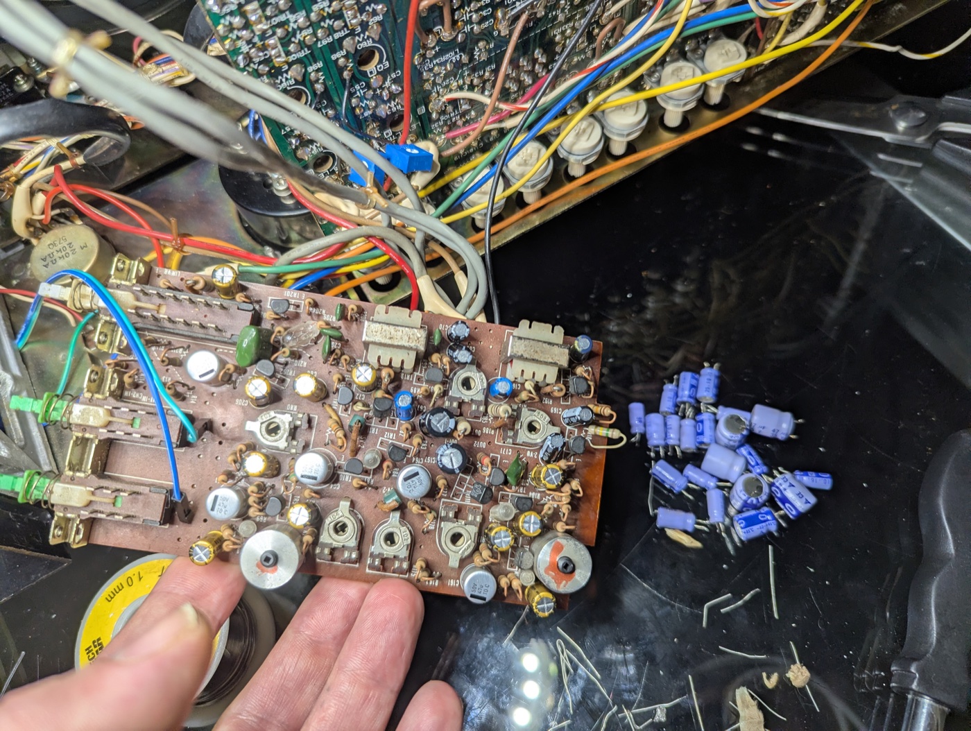 The line-out board after session 2, component side up and still wired into the loom — fresh cans among the trimmers, and the 1977 originals piled on the deck beside it, purple sleeves and clipped leads
Session 2 is done. Same flip-and-solder method as before — mounting screws out, the board worked over with every conductor still soldered to it — and the whole session 2 list above went through in one sitting: the twenty-two positions on PA-285 (PM-680-1), from the input couplings to the line-out and phones couplings. The pile of purple-sleeved 1977 electrolytics on the deck is the whole audio path's worth of originals, out for good.
That completes the playback recap the plan above promised: both boards in the replay chain, about 37 capacitors across two sittings. What's still owed is the exit test, and it hasn't moved: demagnetizer pass now that the iron is cold, then the full junk-tape run — both channels, both speeds, a complete reel.
The record side got its turn next — Recap complete finishes the job: the input board, the record amplifier, one broken wire, and the first recording.
The three rules that outrank the solder
- Demagnetize the heads first — and again after each session. Decades of tantalum leakage may already have left a little permanent magnetism in them, and a magnetized head quietly degrades every tape it plays. The bench work itself is the other risk: desoldering transients and first power-ups are one-way current events, exactly the kind that magnetize a head in a single hit. One pass with the demagnetizer before any serious playback, and another after each session's iron goes cold.
- Nothing irreplaceable touches the machine until both sessions are done and a sacrificial tape has played a full reel clean — both directions, both speeds.
- Record the baseline. A minute of a junk tape through the interface before the first capacitor comes out. When the work is done, that file is the honest before/after — for my ears, and for this log.
Why the demagnetizer earns a rule of its own, in pictures:
Why microamps get watched, and why the demagnetizer runs after every session.
A worn capacitor lets a whisper of one-way current through the replay head. Slowly, the head itself becomes a weak permanent magnet.
The numbers
Steady leakage in the microamp range is mostly survivable — practitioner rule of thumb puts real danger orders of magnitude higher. Replay-head magnetization = raised noise floor + progressive short-wavelength (HF) erasure. Distortion and pops belong to record/erase-head magnetization. Fail-short endpoint documented in tantalum reliability literature (KEMET/AVX). Remedy: AC demagnetization before serious playback and after each bench session.