2026-07-23
Recap complete
The playback-first recap ended with a promise: playback done, "out of the sixty-plus a full recap will eventually touch." This entry pays the rest. The record side — the mic and line input board and the record amplifier — is now on fresh capacitors too, and the machine has done the thing all of this was for: it recorded, from mic and from line, both channels, and played it back.
Every audio electrolytic on all three boards is new. The 1977 originals are out for good.
Session 3 — the record side
The parts this session had been waiting for arrived first: the guaranteed low-leakage order — UKL 10 µF/100 V for the sensitive couplings, Rubycon TWL 10 µF/25 V for the rest of the 10 µF positions, and TWL 33 µF spares for the line-out value session 2 already fitted.
Session 3
PA-287A (PM918A) + PA-286A (PM917A) record side · 42 positions
| ☐ | Position | Original | Role | Fitted |
|---|---|---|---|---|
| ☐ ☐ | C1 / C101 | 10 µF/16 | Mic input coupling | TWL 10 µF/25 V |
| ☐ ☐ | C3 / C103 | 100 µF/16 | Mic first-stage bypass | bench stock |
| ☐ ☐ | C5 / C105 | 22 µF/16 | Emitter bypass | bench stock |
| ☐ ☐ | C6 / C106 | 10 µF/35 | Coupling → mic level control | TWL 10 µF/25 V |
| ☐ ☐ | C7 / C107 | 100 µF/25 | Stage decoupling | bench stock |
| ☐ ☐ | C8 / C108 | 47 µF/35 | +B decoupling | Vishay 013 RLC 47 µF/50 V |
| ☐ ☐ | C9 / C109 | 10 µF/16 | Line-in coupling (from line level control) | TWL 10 µF/25 V |
| ☐ ☐ | C11 / C111 | 10 µF/35 | Interstage coupling | TWL 10 µF/25 V |
| ☐ ☐ | C12 / C112 | 10 µF/35 | Coupling into the output stage | TWL 10 µF/25 V |
| ☐ ☐ | C14 / C114 | 47 µF/16 | Output-stage bypass | Vishay 013 RLC 47 µF/50 V |
| ☐ ☐ | C16 / C116 | 10 µF/35 | Output coupling → record EQ | TWL 10 µF/25 V |
| ☐ ☐ | C354 / C374 | 10 µF/35 | Sel-rep decoupling | TWL 10 µF/25 V |
| ☐ ☐ | C355 / C375 | 10 µF/16 tantalum | Sel-rep input coupling | UKL 10 µF/100 V |
| ☐ ☐ | C358 / C378 | 10 µF/35 | Sel-rep interstage | TWL 10 µF/25 V |
| ☐ ☐ | C360 / C380 | 10 µF/35 | Sel-rep output coupling | TWL 10 µF/25 V |
| ☐ ☐ | C365 / C385 | 10 µF/35 | Sel-rep decoupling | TWL 10 µF/25 V |
| ☐ ☐ | C23 / C123 | 10 µF/16 | Record-amp input coupling | TWL 10 µF/25 V |
| ☐ ☐ | C24 / C124 | 100 µF/6.3 | Emitter bypass | bench stock |
| ☐ ☐ | C25 / C125 | 10 µF/25 tantalum | Record-amp output → bias trap → record head | UKL 10 µF/100 V |
| ☐ | C302 | 100 µF/35 | Record relay supply | bench stock |
| ☐ | C303 | 100 µF/35 | Record relay supply | bench stock |
| ☐ | C304 | 22 µF/35 | Bias oscillator | bench stock |
| ☐ | C305 | 47 µF/35 | Bias oscillator supply | Vishay 013 RLC 47 µF/50 V |
And one revisit: C51/C151, the replay-head inputs, traded their session-1 stand-ins for the UKL 10 µF/100 V parts the plan originally called for — the second thermal cycle session 1 said it would avoid, spent deliberately on this pair alone.
 The input board flipped solder-side up for the session, still wired into the loom — fresh joints along the switch edge, the record and sel-rep switch pads bright against the older solder
Same method as the first two sessions — mounting screws out, the board flipped over on its loom, every conductor still soldered to it. The input board is the busiest of the three, and the schematic's tantalum census came good: C355 and C375, the sel-rep input couplings, wore the Ⓣ mark, and so did C25 and C125 on the record board — the pair that couples the record amplifier through the bias trap to the record head itself. Those four positions, plus the two replay-head inputs revisited, are where the six 100-volt UKL parts went: every capacitor that faces a head now carries the guaranteed 0.002CV grade, derated to a fraction of it by the voltage headroom. C73 and C173, one node back in the EQ feedback, keep their session-1 cans — that pair earned no second thermal cycle on forty-nine-year-old pads.
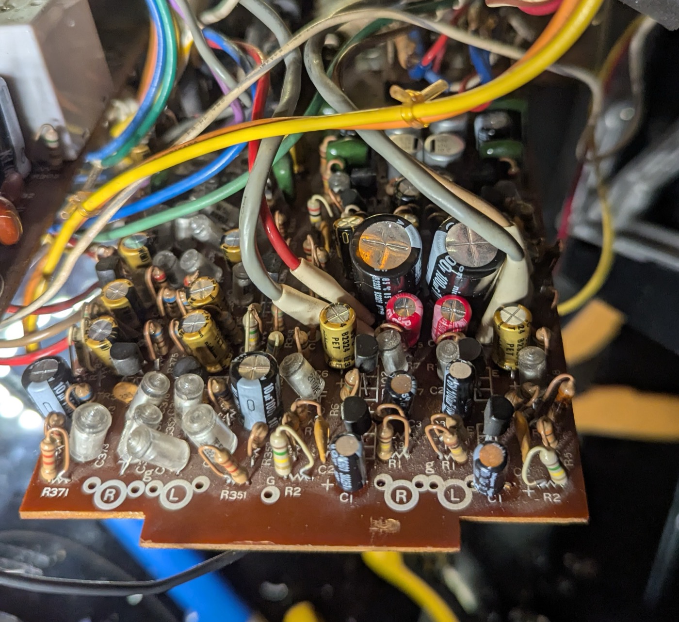 The record amplifier zone on fresh capacitors — black low-leakage cans and silver bypasses where the 1977 originals stood, the relay covers beyond
The machine bites once more
First power-up after the input board, and channel 1's line input was dead. Not weak — dead: zero on the meter, channel 2 passing signal happily, and both mic inputs fine.
That symptom pattern does most of the diagnosis by itself. Mic working on channel 1 clears everything downstream of the point where mic and line paths merge — record amplifier, meters, monitoring, all of it. Line working on channel 2 clears the source and the cable. What remains is the short stretch that only channel 1's line signal touches: the jack, its wiring, and the input stage.
A swap test at the rear panel kept the fault with the machine. Exercising the controls changed nothing — no crackle, no intermittent, which ruled out the classic dirty pot. Stone dead means a broken connection, and the continuity meter found it in minutes: the wire from the line-in jack to its input transformer had broken. One resolder, and channel 1 came back.
Forty-nine years of service and the machine saved its simplest fault for last.
The oscillator that wouldn't peg
The built-in test oscillator was the session's other scare. Switch to OSC, and the meters climbed — but nowhere near the pin, and no amount of staring at fresh solder joints explained why.
The answer wasn't on the boards. The oscillator feeds the record chain through the line-input level path — so the OSC test's meter reading is set by the line-in control, by design. The meters weren't failing to peg; they were waiting to be set: oscillator on, line level to reference, calibrate from there. Mystery closed, no fault found, one small lesson filed about reading the signal path before doubting the solder.
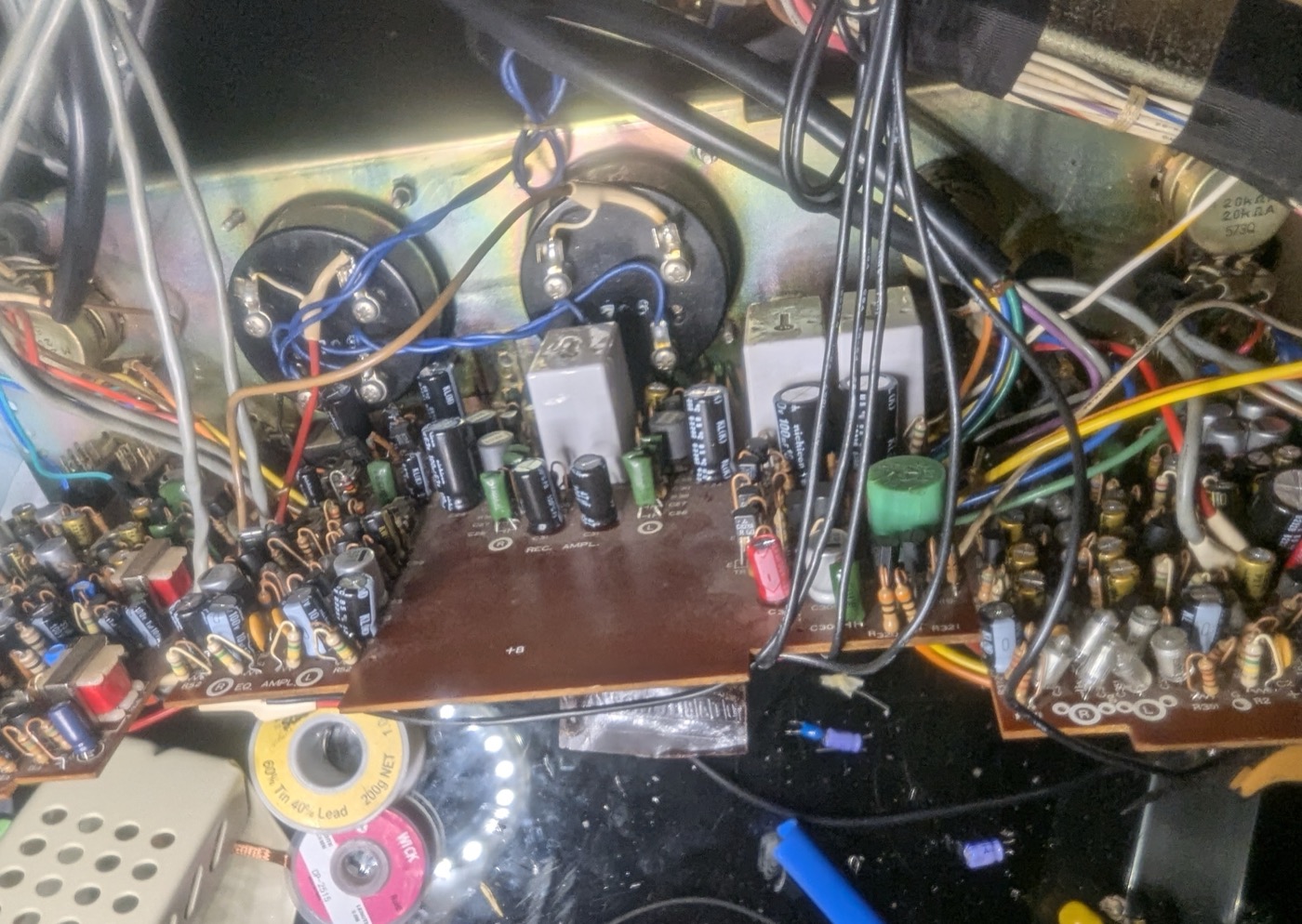 The bench at the end of the session — all three boards on fresh capacitors, the meters waiting, solder and wick spent
The debt still stands
Honesty clause, carried forward from session 1: the leakage measuring rig still hasn't happened. There is still no bench supply worth trusting, so every one of these parts went in on its datasheet guarantee and the derating physics — including the six UKL positions bought precisely so the guarantee would be there. The plan is unchanged: when a proper supply lands, siblings from the fitted lots go through the 10-volt, two-minute rig, and the numbers get logged here whatever they say.
It records
A junk tape, record enable, and the machine did the rest: recorded from the microphones, recorded from line in, played both back — both channels, both speeds. Somewhere in a 1977 build plan this was row one: a machine that records and plays. It does both again.
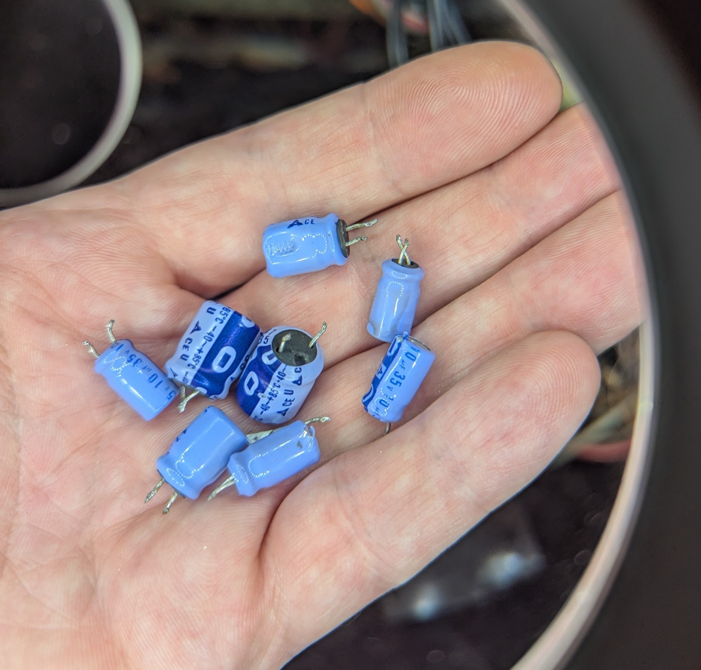 The last of the 1977 originals — pale blue cans with clipped leads, gathered in a palm
What stands between here and my father's tapes is calibration, not repair: the manual's performance tests — frequency response, signal-to-noise, bias — on a machine that finally has the electronics to pass them. That's the next entry.