2022-01-01
Rebuilding the interconnection cable
On AudioKarma
Happy Holidays.
I have a favor to ask. During a move I misplaced the 10-conductor cable that interconnects the tape transport to the electronics. DANG! I have sourced the Cinch-Jones connectors. Now I need to figure out the cable specs. I have in my stock plenty of 10-conductor #22 AWG cable that I planned to parallel to each electronics section. That way the first section of cable will not have to carry the current for both electronic sections. Anyway, here are my questions:
- Is 22 gauge anywhere near the correct size for the current requirements of the electronics power supply?
- Pin #1 of the interconnection cable is shown as "Bias". The signal wire is shown shielded on the electronics section schematic. Am I going to have to make up a custom cable assembly with a shielded wire for this one connection or may I simply use 10 single conductors? May I use shielded 10-conductor cable or does the Bias wire require that it be independently shielded? Can anyone take a look at their cable for me and let me know what Otari did? Diagram below shows the way the cabling was originally setup as I remember it.
Thanks everyone;
P.S. I can't believe I lost this cable >sigh<
On TapeHeads
Hello Sir and thanks for the reply! I am planning on duplicating the "stock" length which I seem to remember at about five feet from the transport and around a foot to jump from the channel 1/3 electronics to channel 2/4 electronics.
I will absolutely follow your guidance. I figured the following would be OK configured as follows:
Pin 1 (BIAS) – individual single conductor shielded cable with the shield connected to Pin 8 (GND A) at all three connector points; transport, first section electronics, second section electronics. I am hoping this scheme will not create a ground loop and that the open end of the shield will reside inside the equipment that is interconnected.
Pins 2 thru 10 (various grounds / AC 55 volts / +29 VDC / REC lamp / EQ) – Nine separate #18AWG conductors. I am thinking that twisting the AC wires will not be needed. I also believe that the EQ signal is only a voltage source to drive Q3 (relay driver) and who-knows-what on Pin 12 of the Reproduce electronics. Some sort of transistor switch to toggle between two playback EQs is my guess.
I have ordered mesh sleeving to contain the entire mess of wires.
Sound like a winner?
On this unit Otari only provided one (1) single output connector on the tape transport that they used to support the all electronics. This one, single connector was expected to support up to eight channels of audio! I know for sure my quad deck (two audio sections) utilized this unique "daisy-chain" design. Pretty sure even the eight channel versions did the same.
Are you proposing that this modified wiring scheme would be a better choice than the original?
01/01/2022
Will wire up as recommended. Please keep me on alert if you want to hear about the outcome of this epic project. I will finish up this post with the result.
Thank you my Otari Brother. I can now move forward with the confidence you have provided.
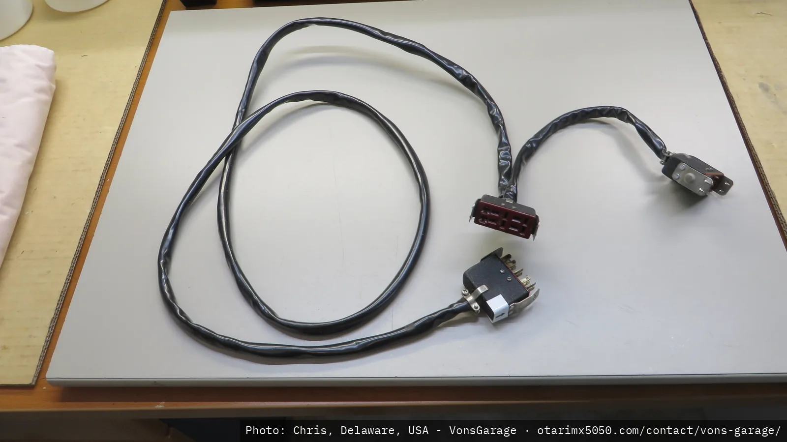 OEM cable, overview
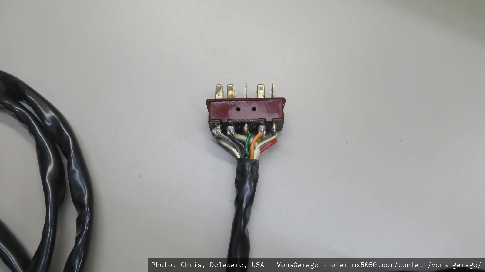 OEM cable, closeup (1)
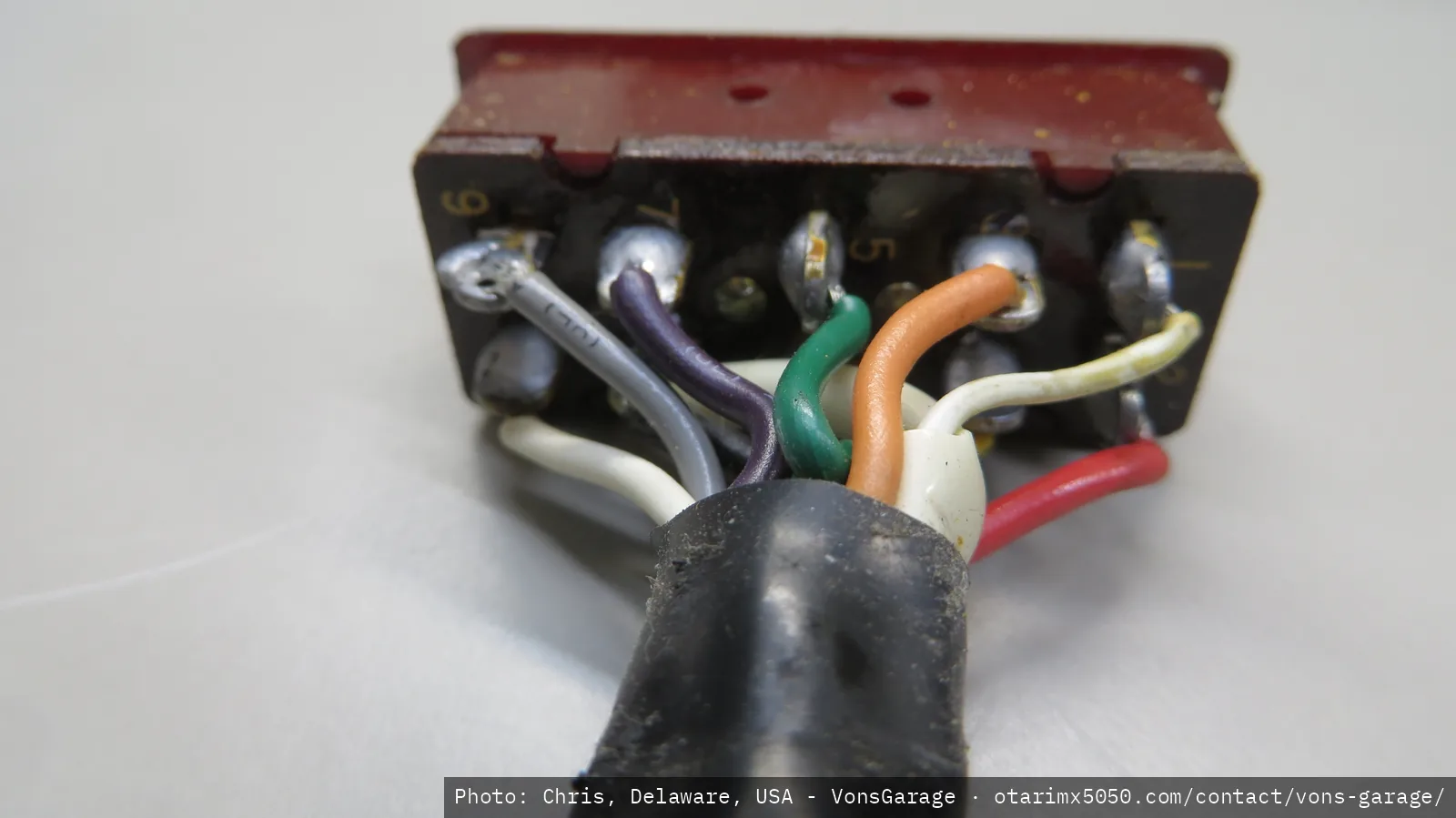 OEM cable, closeup (2)
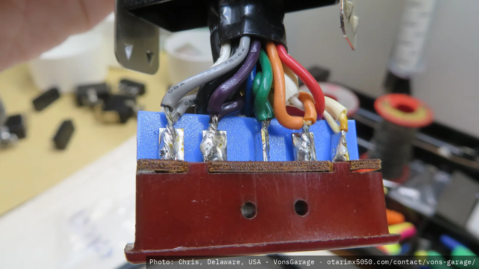 OEM cable: add safety barrier
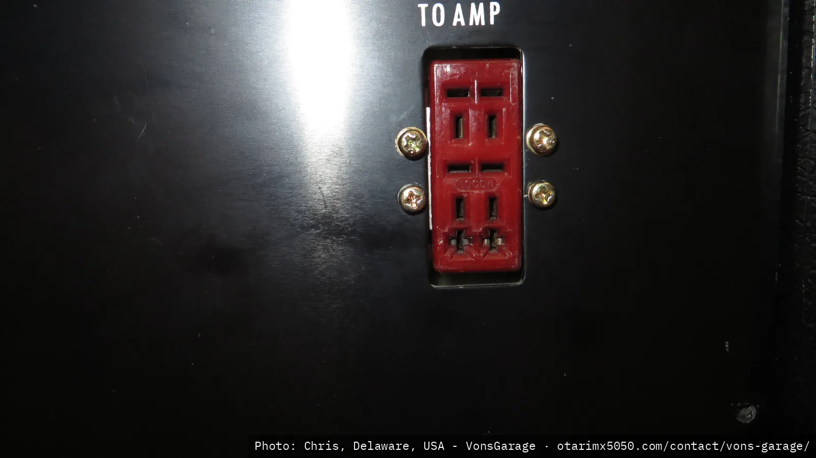 Rear panel connectors, closeup
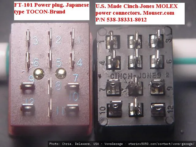 Cinch-Jones and Tocon comparison
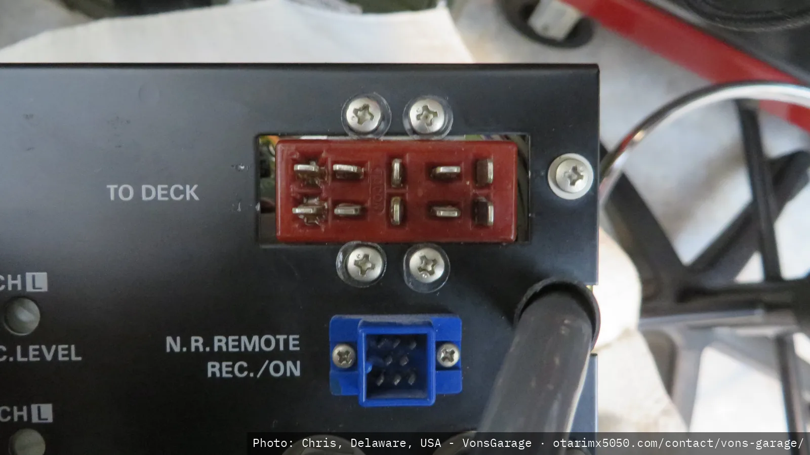 Reworked NR connector to rear mounting: before
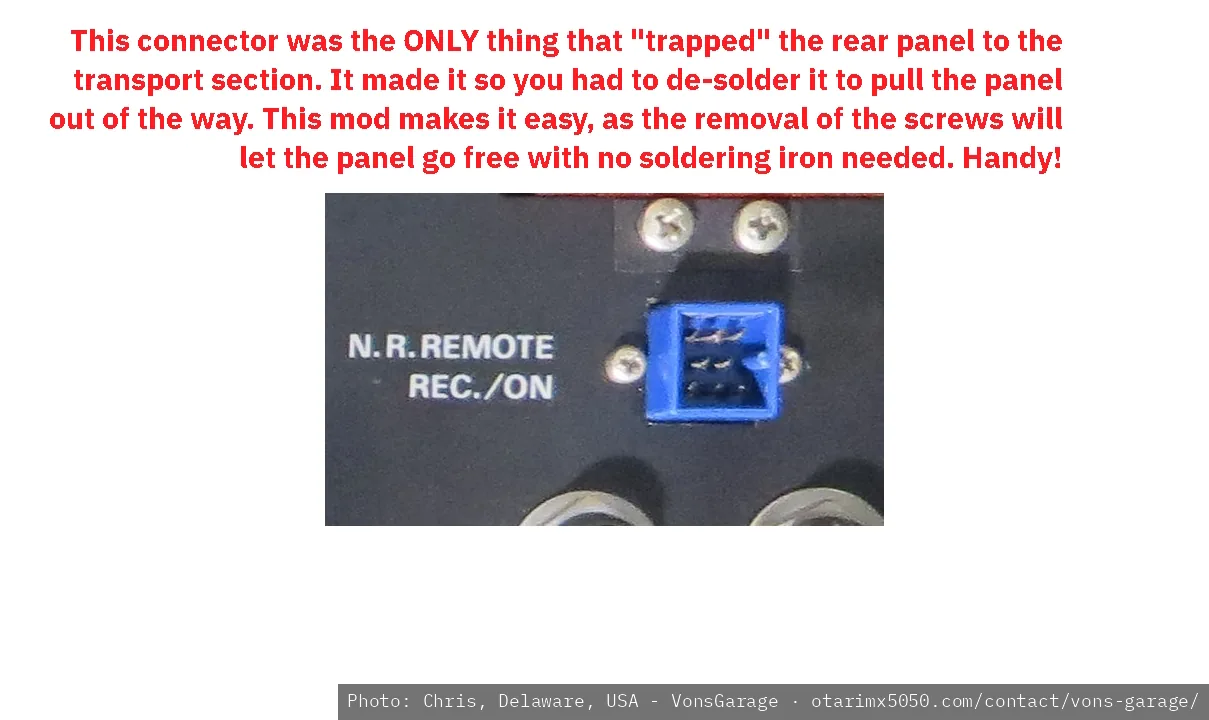 Reworked NR connector to rear mounting: after
UPDATE: I found the cables! I had laid them in a Red Craftsman Toolbox drawer for some reason. I found them just as I was breaking out the soldering iron to make new ones. I had even bought all new CINCH connectors!