2026-07-14
The eight parts that keep the switches alive
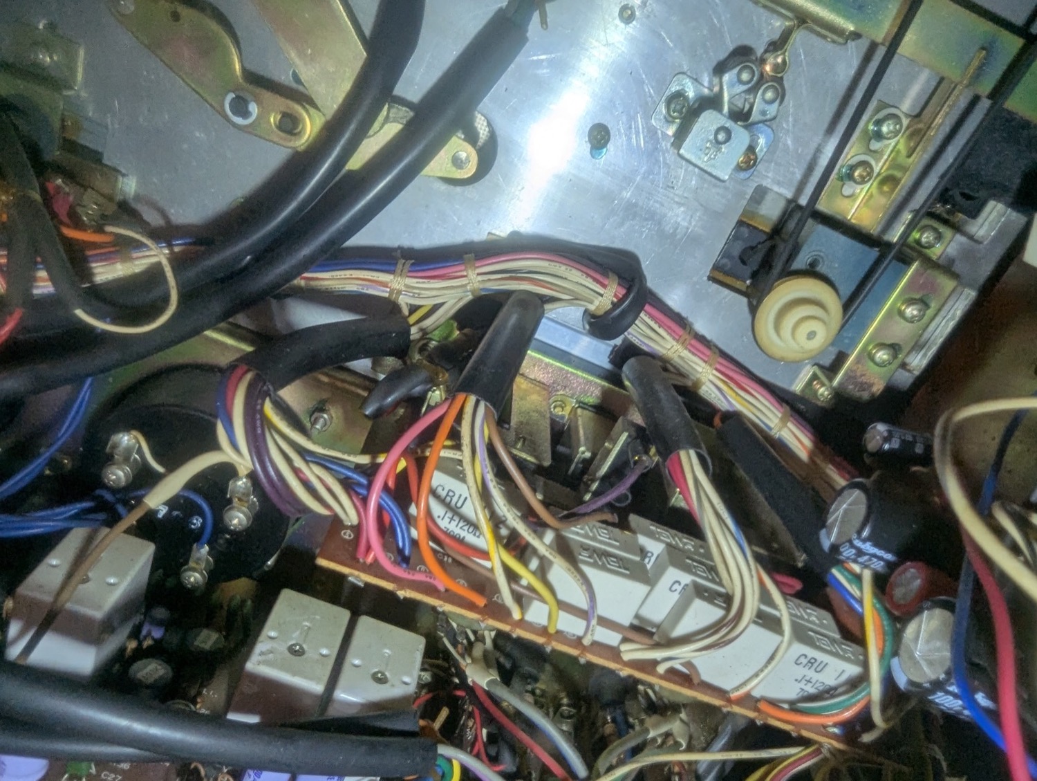 The switch board with its original RC networks still fitted: a row of white CRU 112 blocks, marked .1+120Ω, sitting across the contacts of the POWER, SPEED, REEL and EDIT switches
Along the back of the switch board — the one carrying POWER, SPEED,
REEL and EDIT — there is a row of small white blocks marked
CRU 112, .1+120Ω. Eight of them, one per switch section, at C25, C26,
C27, C31, C32, C33, C34 and C39. They aren't in the signal path. They don't
do anything you can hear. Pull them all out and the machine will work
exactly as it does now.
They are also the only reason the switch contacts have lasted 49 years. All eight are now out, and eight modern X2-rated Roxburgh RE1201 spark quenchers are in their place.
What an RC network across a switch actually does
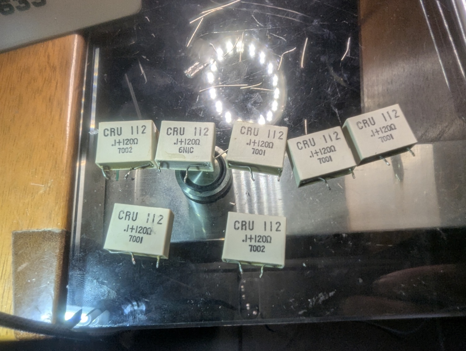 Six of the original CRU 112 RC networks on the bench: 0.1 µF in series with 120 Ω, in a moulded plastic case
Every switch on that board breaks an inductive load. POWER breaks the transformer primary. SPEED and REEL and EDIT switch the capstan and reel motor windings and their run caps. An inductor's whole personality is that it refuses to let its current change: interrupt it and it will generate whatever voltage it takes to keep that current flowing. As the contacts part, the voltage across the gap climbs by hundreds of volts in microseconds — far faster than the gap itself is opening — and the air breaks down. An arc strikes across a switch you've just told to be off.
The RC network is an escape route. To an edge that fast, a 0.1 µF capacitor looks very nearly like a piece of wire, so the inductive current diverts into the capacitor rather than into the arc. The cap charges instead, and the voltage across the contacts now rises slowly enough that the widening gap wins the race and never strikes.
The 120 Ω resistor is the other half of the trick, and it earns its keep twice. On make, it stops the charged capacitor from dumping straight back through the contacts as they close — a bare capacitor across a switch would simply trade an arc on break for a welding inrush on close. And it damps the L-C circuit you have just built, so the trapped energy is turned into a few microjoules of heat in the resistor instead of ringing.
That is the whole job: turn a violent event into a boring one, eight times over, every time you touch the machine.
The thing being protected isn't the capacitor
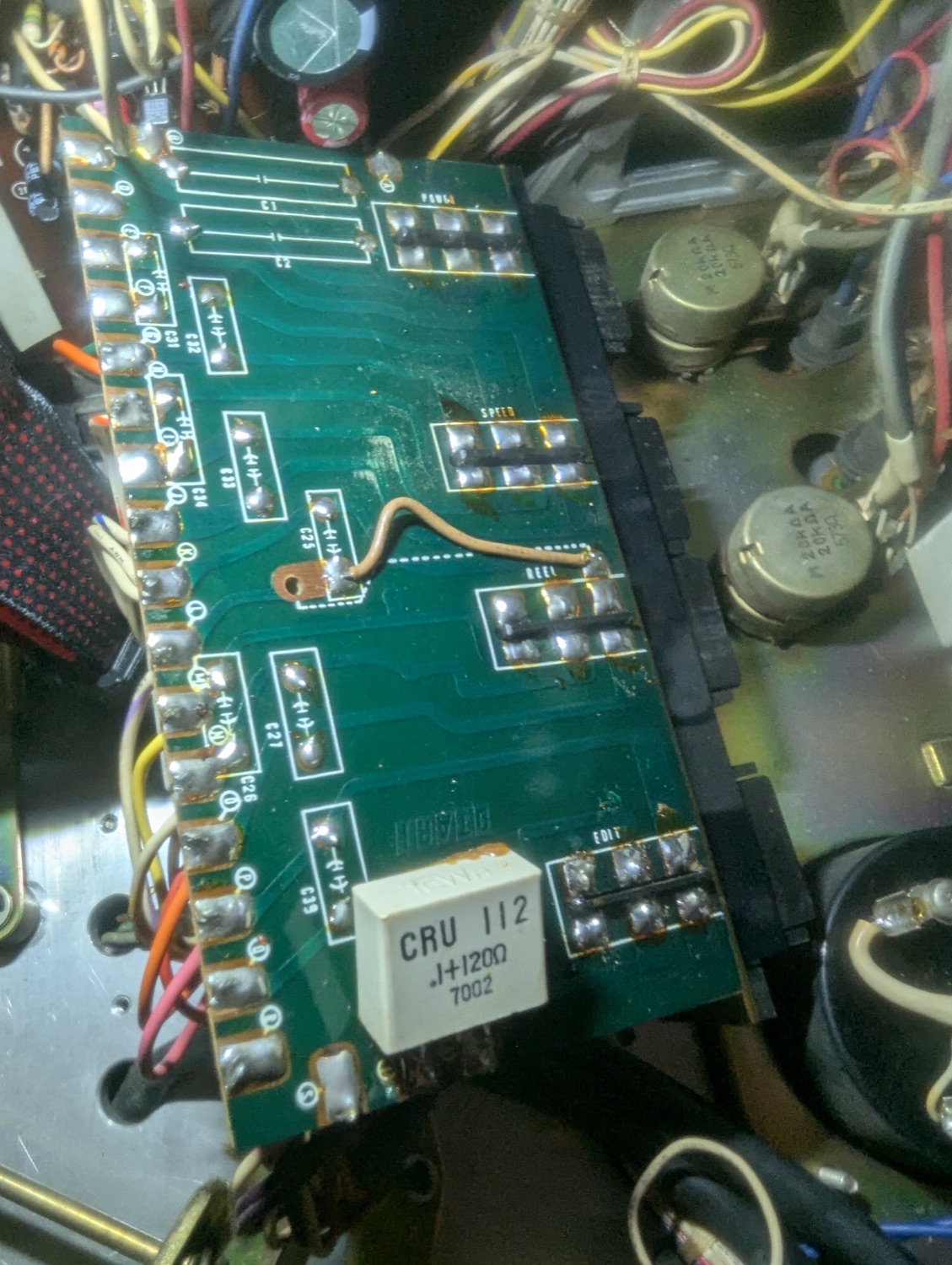 Solder side of the switch board with the RC networks stripped off, their silkscreened footprints empty — one CRU 112 still in place
Every arc vaporises a little metal off the contact faces and leaves a little carbon behind. Do it enough times and the contacts pit, the carbon builds up, contact resistance climbs, and the switch becomes intermittent — then dead. The snubber is a cheap part standing in front of an expensive one.
And on this board, "expensive" is generous. The transport buttons are Omron microswitches you can still buy new. These are not. The POWER, SPEED, REEL and EDIT switch assemblies are Otari's own, soldered to Otari's own board, and there is no catalogue you can order one from. The eight RC networks are the reason that has never mattered.
The arc has a second cost, too: it is a broadband RF burst, right in the middle of a machine full of high-gain audio and transport logic. Quench the arc and you quench the hash.
What "silently" means here
Here is the uncomfortable part. A protective component that is working perfectly and a protective component that died a decade ago produce identical behaviour from the front panel. There is no symptom. There is no warning. Nothing about the machine changes. A 1977 metallised-paper cap in a moulded plastic case has two ways to go, and neither one announces itself.
Fade to open. The dielectric ages and the capacitance quietly drifts downwards until the network stops absorbing anything. The deck behaves exactly as before. Meanwhile, every press of POWER, every nudge of the speed switch, is now drawing a full arc across bare contacts, and the damage is cumulative and lands entirely on the part you cannot replace. By the time you notice — an intermittent speed switch, a deck that needs the power switch wiggled — the harm has already been done, and the snubber that was supposed to prevent it has been dead for years.
Leak to short. The other direction, and the reason old mains-rated caps have a reputation. Moisture works its way into the case over decades, leakage current rises, leakage causes self-heating, heat accelerates the leakage, and the thing ends its life cracking open and filling the room with acrid smoke.
The POWER network deserves a particular stare, because of where it sits. An RC snubber goes across the switch contacts — which means that when the deck is switched off, that capacitor is the component bridging live mains to the transformer primary. It is energised every second the machine is plugged in, on or off, and it has been for 49 years. In perfect health that's fine and by design: 0.1 µF is about 32 kΩ at 50 Hz, so roughly 7 mA trickles through the primary with the machine "off", the resistor dissipates a few microwatts, and nothing happens. What isn't fine is a dielectric that has stopped being a dielectric. Short that capacitor and you have put 120 Ω across 240 V — two amps, some 480 watts, in a quarter-watt resistor. It does not survive that, and it does not fail politely.
So: no measurements, no diagnosis, no waiting for a symptom that by definition never comes. All eight came out on principle.
The replacement
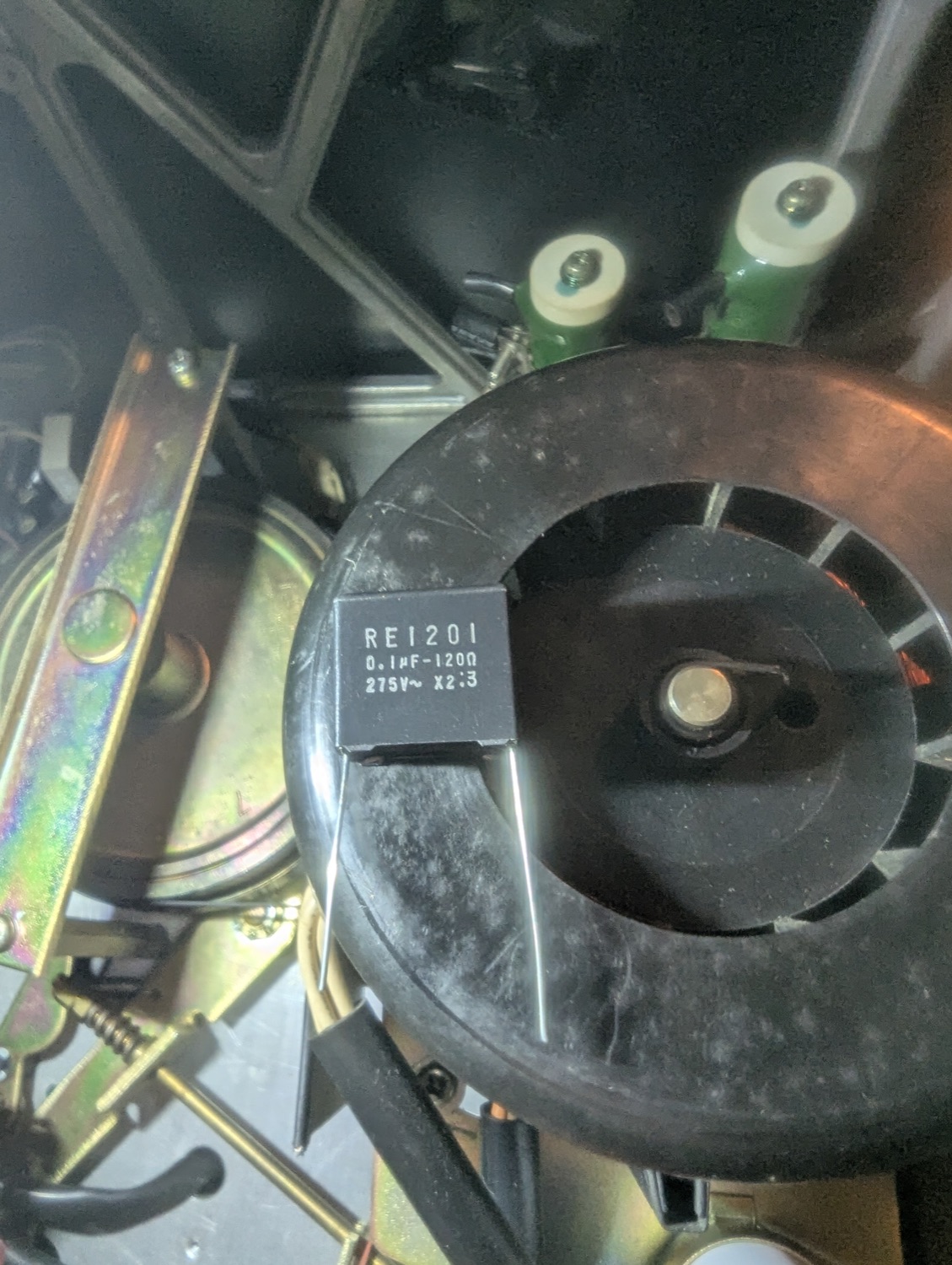 The new part: Roxburgh RE1201, marked 0.1 µF–120 Ω, 275 V~, X2 — a modern X2-class spark quencher with the same values as the 1977 original
The RE1201 is a Roxburgh EMC badge on an Okaya part, and Okaya's own name for the series is a spark quencher. The datasheet's stated application is "suppressing mechanical switching surge" — which is, word for word, the job Otari gave these things in 1977.
Electrically it is the same network: 0.1 µF ±20 % in series with 120 Ω ±30 %, rated ¼ W. Nothing about how the machine behaves changes, and nothing should. It drops straight into the original footprint.
What is different is everything around the values:
- Safety class X2, to IEC/EN 60384-14. X2 is the class for capacitors connected line-to-line — exactly the position an RC snubber sits in — where the part must be built so that failure cannot become a shock hazard or a fire. That standard is what a 1977 part predates, and it is the entire reason for the swap.
- 275 Vac rated, which is real headroom on 240 V mains rather than a number the part is living right up against.
- 1200 V maximum peak pulse, type-tested with 800 V peak-to-peak pulses — the network is specified for the transients it exists to absorb, not merely for the mains it sits across.
- Approved to (c)UL 60384-14, CSA E60384-14 and IEC/EN 60384-14 by VDE, SEMKO, NEMKO, DEMKO, FIMKO and Electrosuisse. Eight independent bodies agreeing on how it is allowed to die.
- −40 to +100 °C operating range, and RoHS — no 1970s chemistry.
The point isn't that Otari got it wrong. They got it conspicuously right: there is a snubber on every switch section on that board, which is more care than a lot of 1977 gear ever saw. The values were correct then and they're correct now. What has changed is 49 years of moisture, and a safety standard that now insists a component living permanently across the mains must have a defined, non-flammable way to fail.
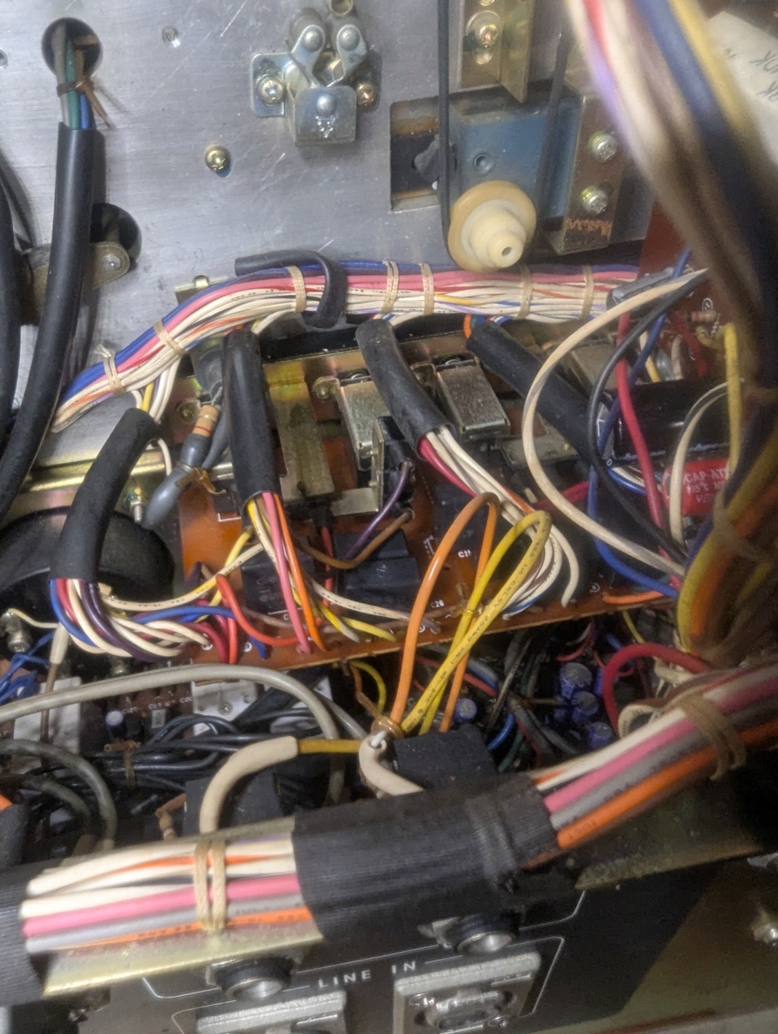 The switch board back in the machine with the job done: black RE1201 spark quenchers where the row of white CRU 112 blocks used to be — same 0.1 µF and 120 Ω, now X2 rated
Back in the chassis, the only visible difference is the colour: a row of black blocks where the white ones were. The machine switches on exactly as it did before, which is the entire point. Nothing about a snubber is supposed to be noticeable — it just has to be there, and to still be working, on the day the contacts need it.
If you own one of these
Pull the switch board and look, even though everything works — especially
because everything works. That's the trap. Eight parts, a couple of dollars
each, and the only feedback loop they have with you is the one where they've
already stopped protecting the switches and you find out years later. The
values are printed right on the case: .1+120Ω. Buy eight, fit eight, and
put the arc back where it belongs, which is nowhere.