2026-09-06
The meters mean something now
The calibration article has said for a month that the first electrical step is the one that makes the VU needle mean something. Today it happened, and it taught me more about measuring than about the deck.
The meter arrives
The test equipment page settled on a UNI-T UT61E as the budget true-RMS multimeter, and the one that landed is its successor, the UT61E+: 22,000 counts, true RMS on AC volts, and a frequency mode that will matter for the speed check later. Its job in this step is narrow and load-bearing: it is the only thing on the bench that knows what a volt is.
The step
Otari's maintenance manual, 3-5-(2), is two sentences: hold TEST OSC, adjust INPUT LINE until the voltmeter on LINE OUT reads +4 dBm, then trim the VU CAL pots until each meter reads 0. With LINE OUTPUT LEVEL at HIGH, +4 dBm is 1.23 V RMS across the output. The pots are R86 for CH-1 and R186 for CH-2, and they live on PA-285, the test-oscillator and line-output board — the same PM-680-1 the recap sessions went through. On the layout drawing they are the two big horseshoe trimmers low on the board, each sitting above a headphone transformer; the other three horseshoes along the top are the output-stage balance and idling adjustments, which are not to be touched for this.
Before any of it, the mechanical zero: the small screw beneath each meter sets where the needle rests with no signal. Both were a whisker off the rest mark and got set first, because a needle that doesn't rest true can't be trimmed true.
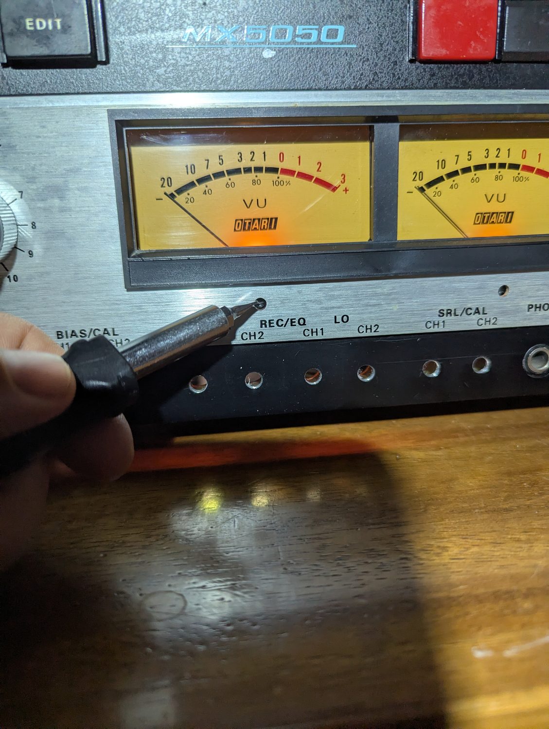 A small screwdriver at the mechanical-zero screw beneath the CH-1 VU meter, both needles resting at the left-hand rest mark with no signal
The trap
The LINE OUT connectors are male XLRs, and the manual's installation section is clear about them: pin 3 is signal, pin 2 is the return, pin 1 is the shield. My first readings were taken between pin 3 and the connector body, on the assumption that the shell is ground. It isn't a clean one on this deck. Against the shell the numbers wandered — 1.02 V, then 1.66 V with no signal at all, then 1.89 V with the tone — and the needle sat pinned hard right, which sent me down a path of suspecting a weak oscillator and a capacitor passing DC to the meter.
Against pin 2, the deck behaved. No signal: a dead 0 V, so nothing is oscillating or humming. TEST OSC held with INPUT LINE fully clockwise: 2.28 V, which is +9.4 dBu — well above the target, not below it. The pinned needle was simply a meter being driven five decibels past its top mark. Nothing was wrong except where my black probe was.
The rule that came out of it, for every LINE OUT reading from here on: pin 3 to pin 2, never the shell.
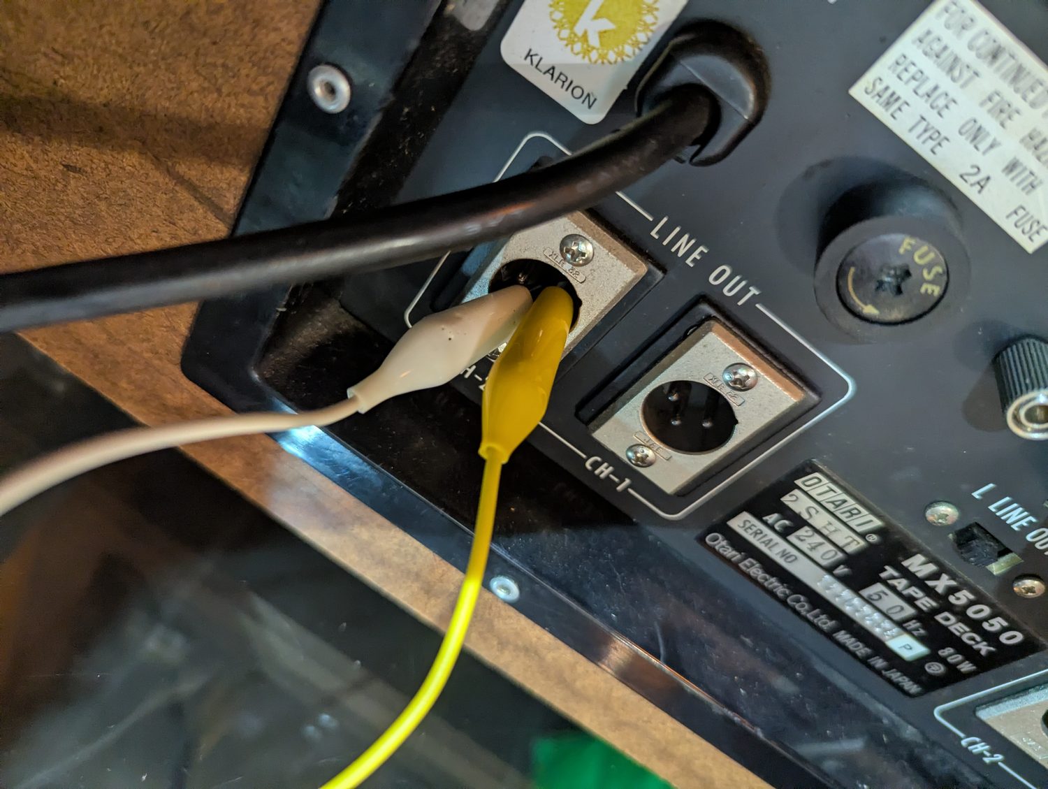 Two clip leads on the pins of the CH-2 LINE OUT XLR on the rear panel, beside the 2SHT model plate and the Klarion distributor sticker
What sets the oscillator's level
Since I had the schematic open, the answer to a question I'd asked myself that morning: the built-in test tone is a two-transistor Wien-bridge oscillator, Tr201 and Tr202, with its frequency set by R207 and R208 against C203 and C204, and its amplitude held by a thermistor, TH201, in Tr201's emitter. There is no level trimmer. The tone reaches the line input through R210 and the TEST OSC switch contact, and its level is whatever the thermistor settles at. At 2.28 V full up, mine has settled somewhere generous.
And the meter's own path, for the record: line output node, R86, C69, into Tr13 as an emitter follower, then out through C70 to the meter. C70 is the capacitor that keeps DC off the needle. It was innocent today.
The numbers
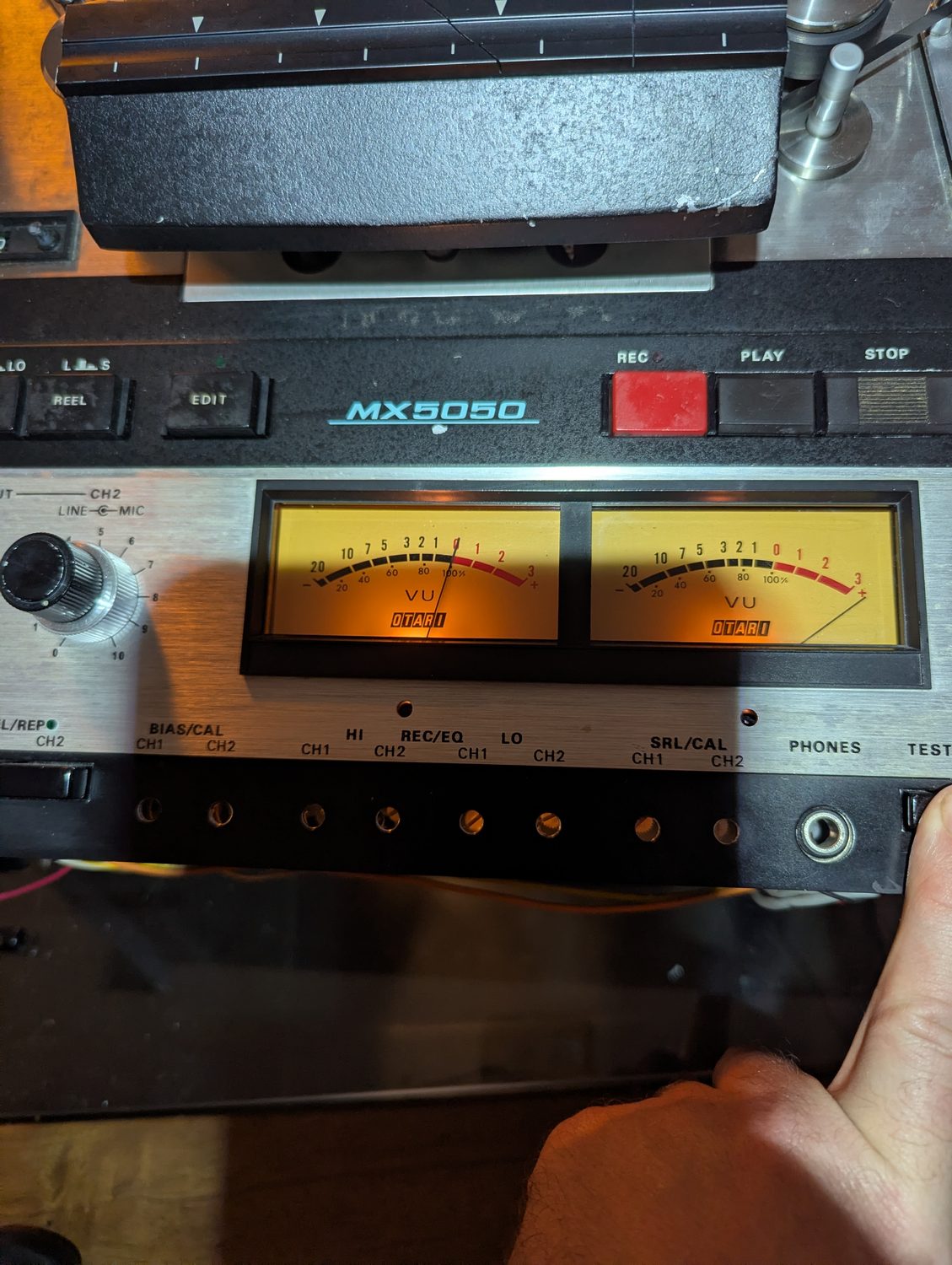 The front panel with CH-1 already trimmed: the left needle sits on 0 while the right one is still pinned past +3 at the same input level, waiting for its own trim
The pinned needle, caught mid-session: CH-1 trimmed, CH-2 not yet. Same oscillator, same level, one meter that has been told what 0 means and one that hasn't.
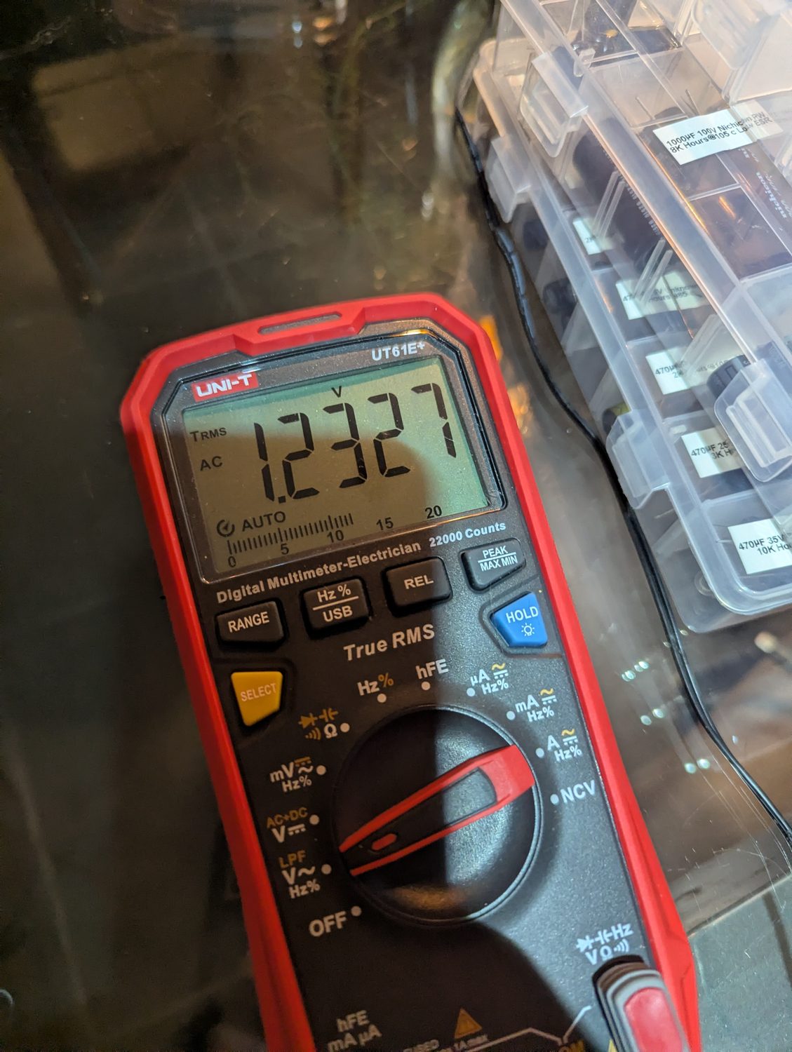 The multimeter reading 1.2327 V AC, true RMS, on the CH-1 line output
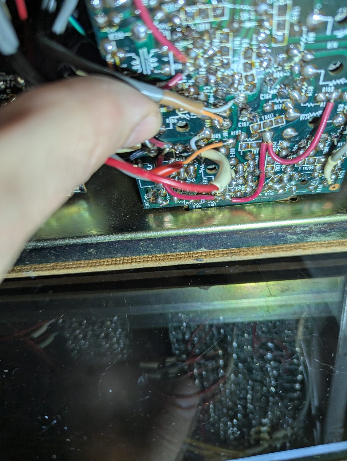 A screwdriver on the solder side of the PA-285 board, turning the CH-2 VU CAL trimmer R186 with the board still wired into the deck
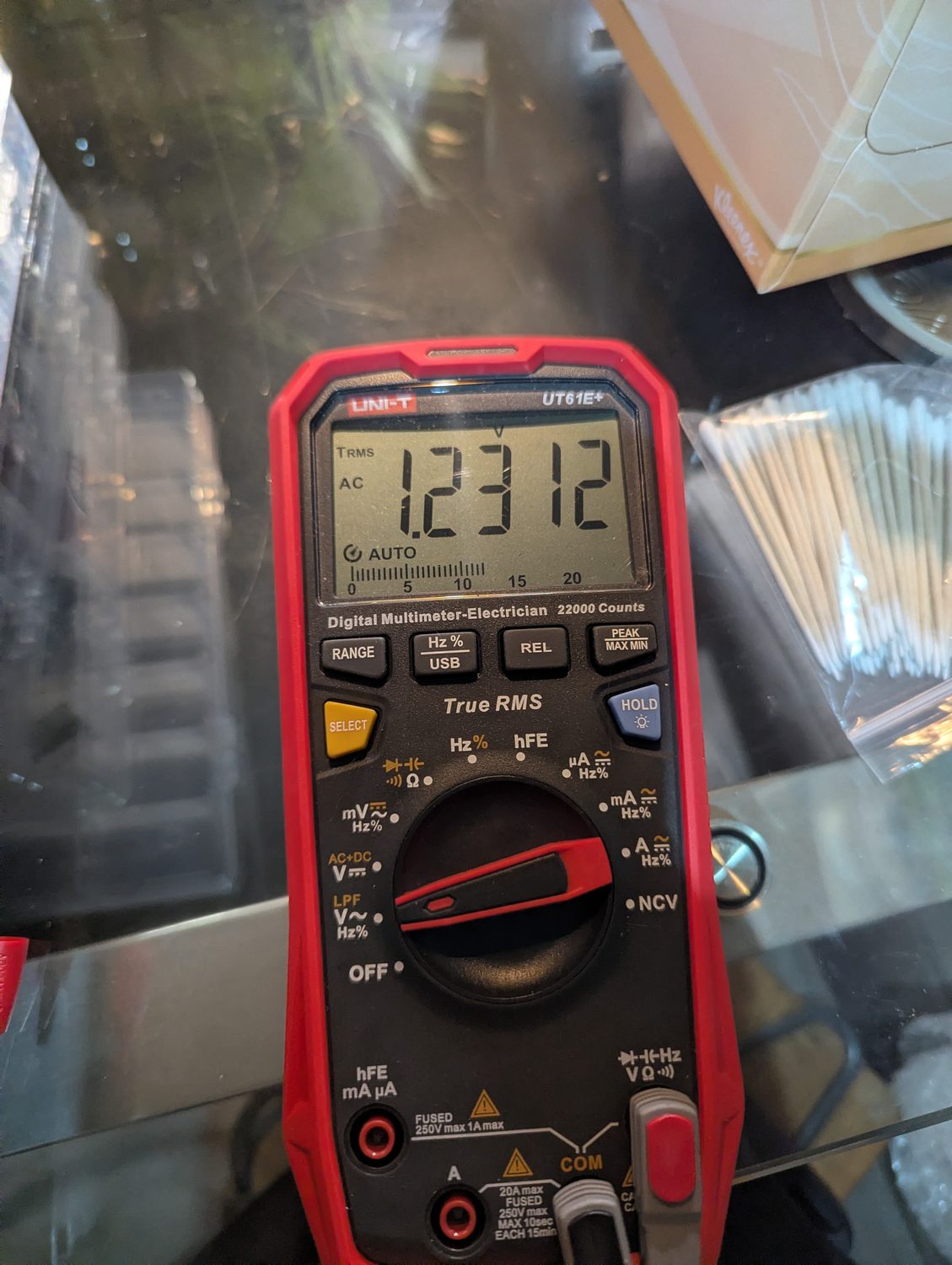 The multimeter reading 1.2312 V AC on the CH-2 line output
| Channel | LINE OUT, pin 3 to pin 2, TEST OSC held | VU meter after trim |
|---|---|---|
| CH-1 | 1.2327 V | 0 |
| CH-2 | 1.2312 V | 0 |
Both within a hundredth of a decibel of +4 dBm. INPUT LINE came down from fully clockwise to get there, not up. Released, both needles drop to their rest marks.
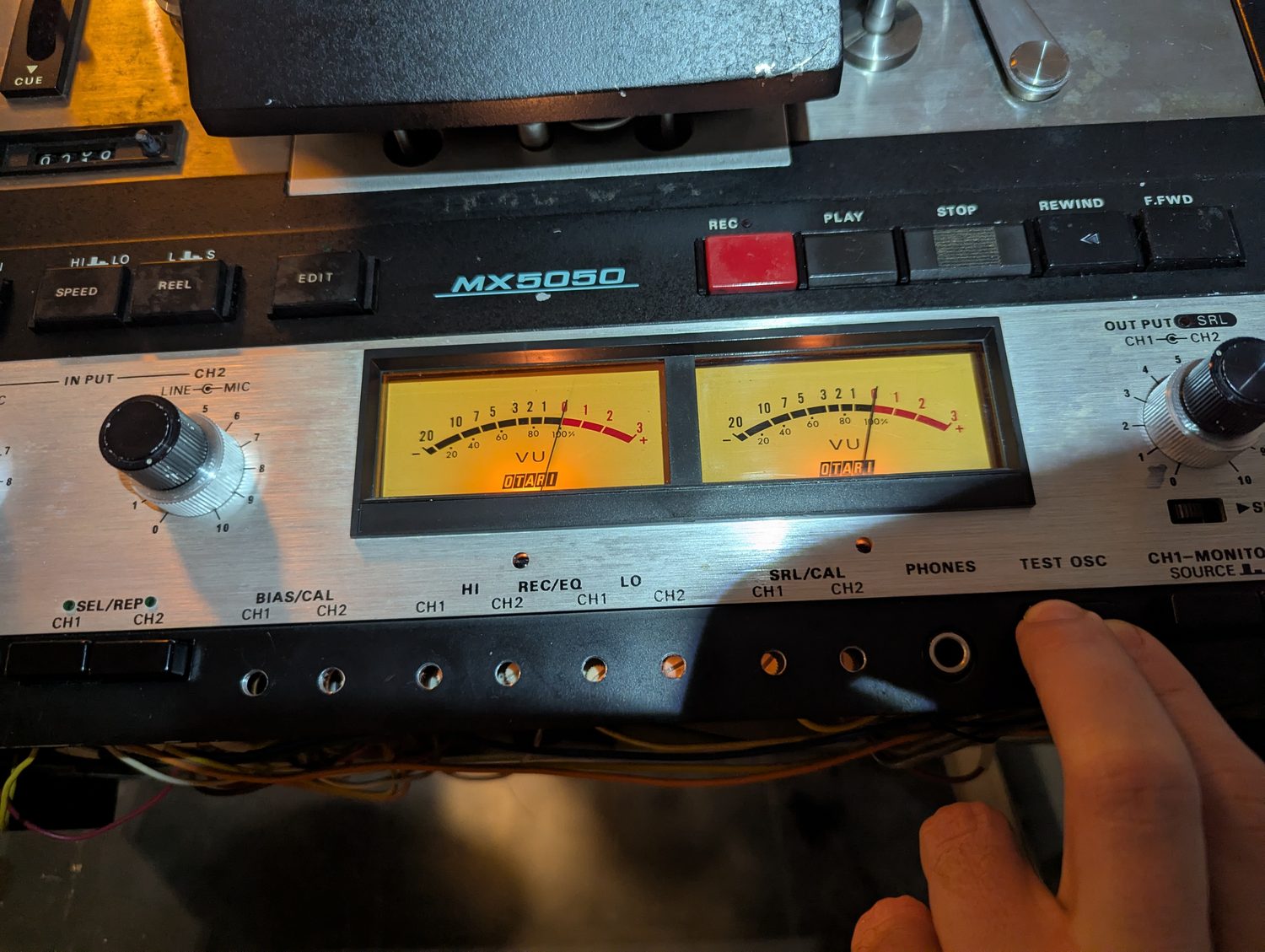 Both VU meters reading exactly 0 with the TEST OSC button held
The switch that does nothing
One more thing surfaced after the trim, and it belongs in the record. The rear panel carries a two-position switch marked L LINE OUT H — the manual's LINE OUTPUT LEVEL selector, +4 dBm or −10 dBm — and mine was at L for the whole session. The manual's setup step says HIGH. On the schematic that should have mattered a great deal: the switch selects a 3 kΩ and 600 Ω attenuator on the way to the XLR, about 14.5 dB, and it sits after the point where the VU meter takes its signal. A meter trimmed to 0 through the pad would be 14.5 dB insensitive once the pad came out.
So I flipped it, and nothing happened. Both positions, same 1.23 V, same needles on 0. On this deck the switch is out of circuit, and the arithmetic says which side it is stuck on: the 2.28 V I had measured at full input could only have come through the pad if the amplifier were swinging 14 V RMS on a 29 V rail, which it can't. The output is on the direct side. The calibration stands exactly as the manual intends it, the switch is a small fault for a day with the lid off, and the bench card on the calibration page now says to check the thing rather than assume it.
What it changes on this site
Two things. First, the calibration article's VU step now carries a short bench card with the probe positions and the trap above, so the next person doesn't measure against the shell.
Second, and larger, though it was found three weeks before this session and has waited for its own write-up: this deck's capstan flywheel was swapped by a previous owner. It runs 7.5 ips at the HIGH position and 3¾ ips at LOW, not the 15 and 7.5 its 2SHT plate promises and the calibration article assumes throughout. That doesn't touch today's step — volts are volts — but it changes the speed check, which alignment tape the SRL step wants, and whether the LOW position's equalization is even right for the speed it now runs. That entry, dated to the day the reference tape gave it away, is The announcer was slow.