2026-10-13
A home-made CR-705 remote with a light for every function
I am guessing the "A" in the part number perhaps meant the remote had a light to tell you it is in record mode. Sounds like a good idea. But no indicator for any other functions. So, I made one that does.
Well, my remote control has lights for every function; even stop.
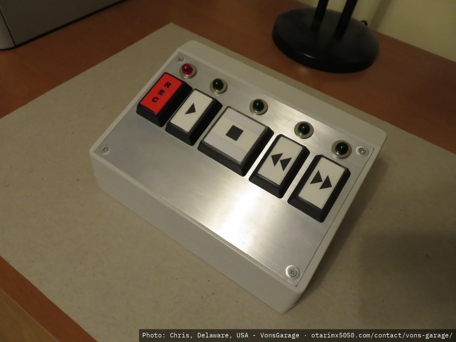 Otari remote, finished product (1)
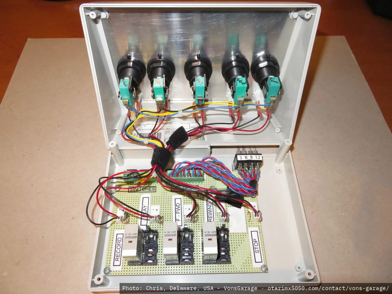 Otari remote, finished product (2)
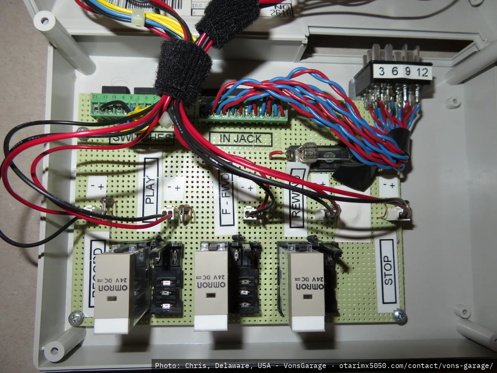 Otari remote, finished product (3)
I thought the switch selection would be cool (I like big buttons – must be from my days working at Chuck E. Cheese as a video game tech) and thought I would be able to use the sockets inside for backlit lighting. Nope. Didn't work. No LEDs that were affordable would fit. So, I added the ugly pilot light indicators on top. I also decided that the Ampex symbol version of the tape functions was a lot cooler than writing out the function that would have copied the original Otari.
Found out all about the Cinch-Jones / Tocon (Yaesu) connector pin numbering fiasco. Is Japan below the Equator; hence the inverse numbering?
Nevertheless; here is a pile of pictures and stuff as it may be helpful if you want to make one with lots of lights. Note that there are mods inside the transport chassis; there goes the warranty. I utilized all the unused pins from the remote rear panel connector. I have no idea what would happen if you plugged in an OEM remote control after this mod is performed so be careful if you have one of them laying around. Hope I haven't created a booby trap.
It is interesting to watch the indicators as you toggle from fast wind operations to play or stop in that right before those slow functions kick in, both the FF and REW LEDs flash for ~1/2 second. That kinda' makes good sense in that it would assist the final slow down by having the two opposing motors "fight" each other for that brief moment. Pretty smart – I think – unless all these circuit mods I made are backing up into the poor ole' logic circuit board. Anyway; so far so good. Been playing around with this thing for quite a while and no issues. Notes:
- I'm sure the circuit is overly complex, but I'm an electro-mechanical guy.
- I think the pictures showing the interconnection between the transport logic board PCB connector and the rear remote connector are self-explanatory. I'm just jumping power, via the socket, to the relays in the remote.
- The doubled relay sockets in the photos are because I started with SPST and realized too late I needed an extra pole for the LEDs. Easier to just leave them in there and add the correct socket next door. My original thought was the LEDs could just be tied in parallel with the relay coils. This caused logic issues and I'm really lucky I didn't blow something up in the Otari!
- The vertical resistors (now jumped out) were current limits for original LEDs that didn't work out.
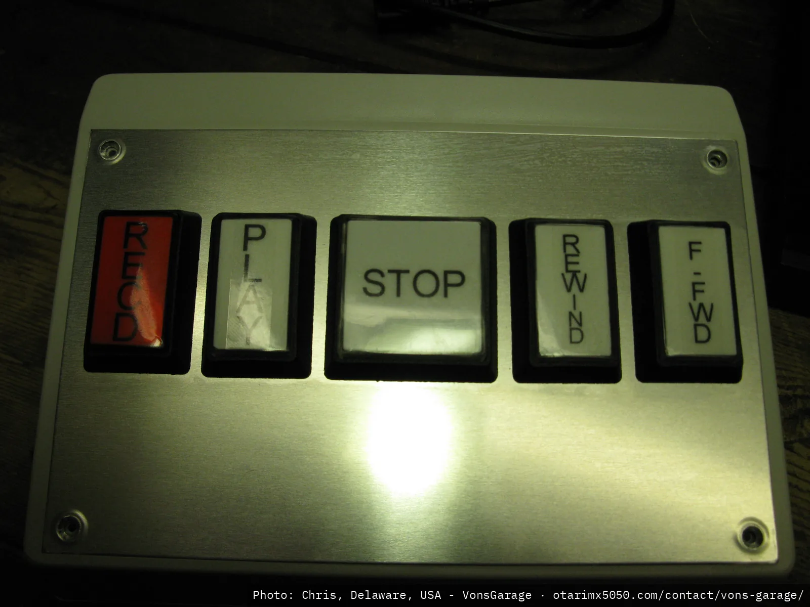 First version: front panel with buttons loaded
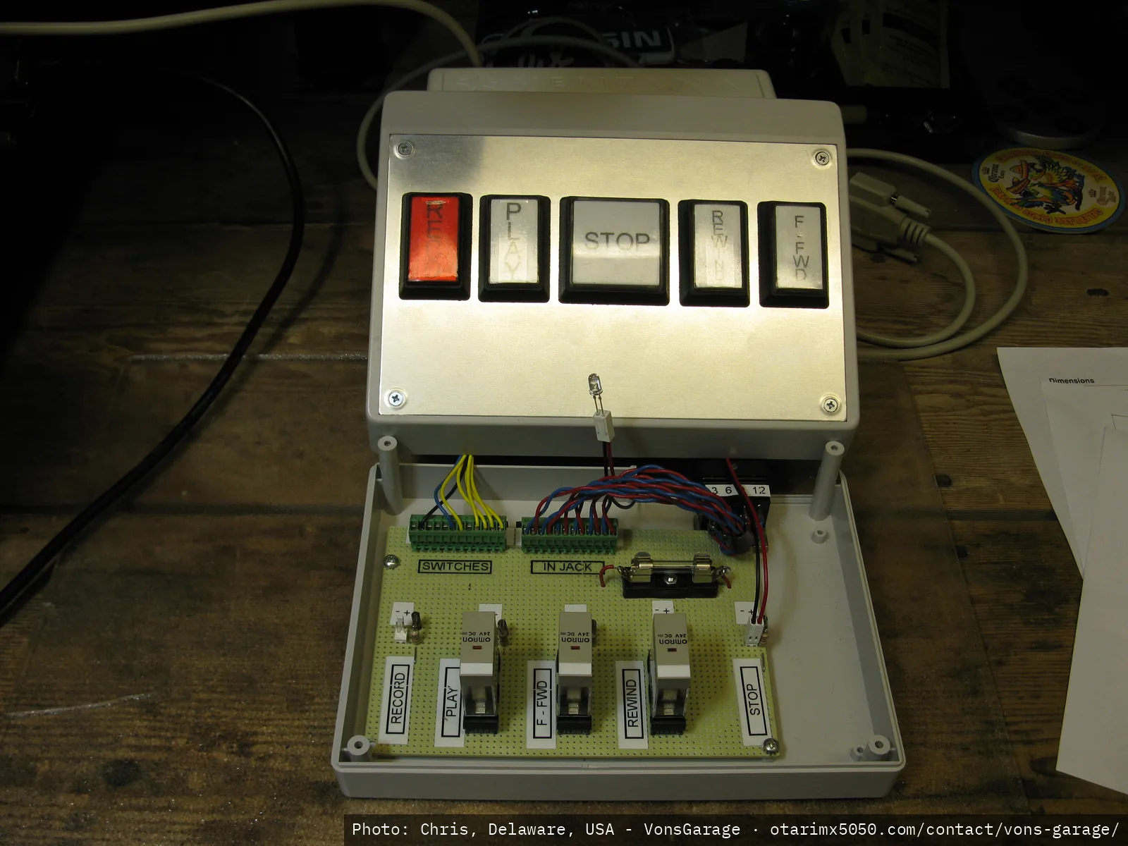 First version: overall view, front and inside
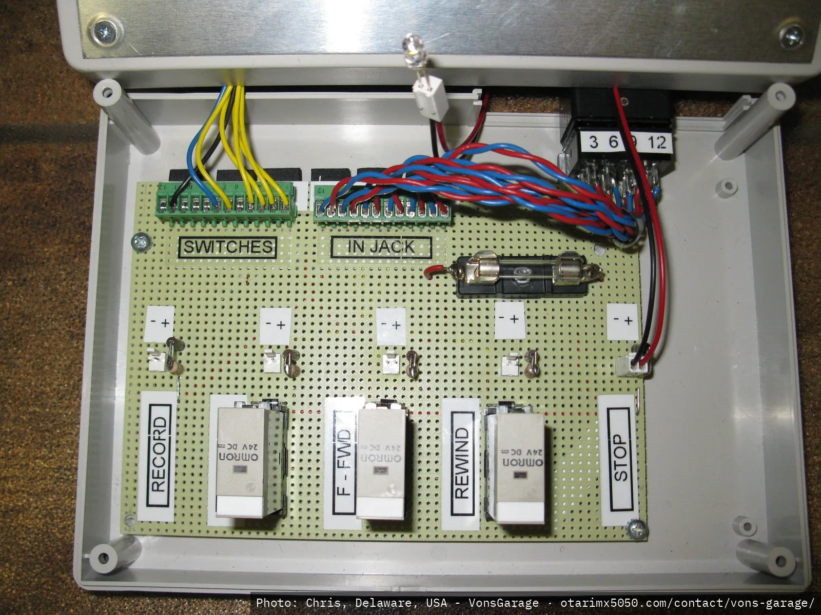 First version: inside view, closeup
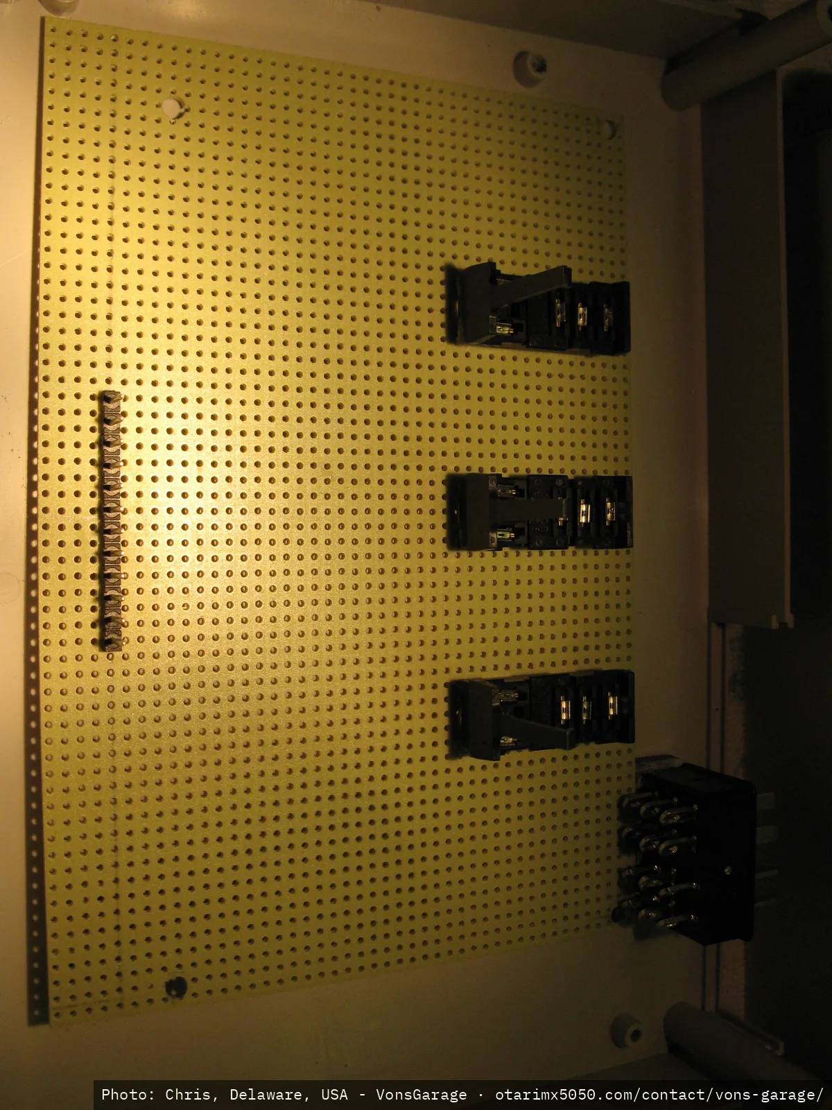 First version: perf board, relay sockets
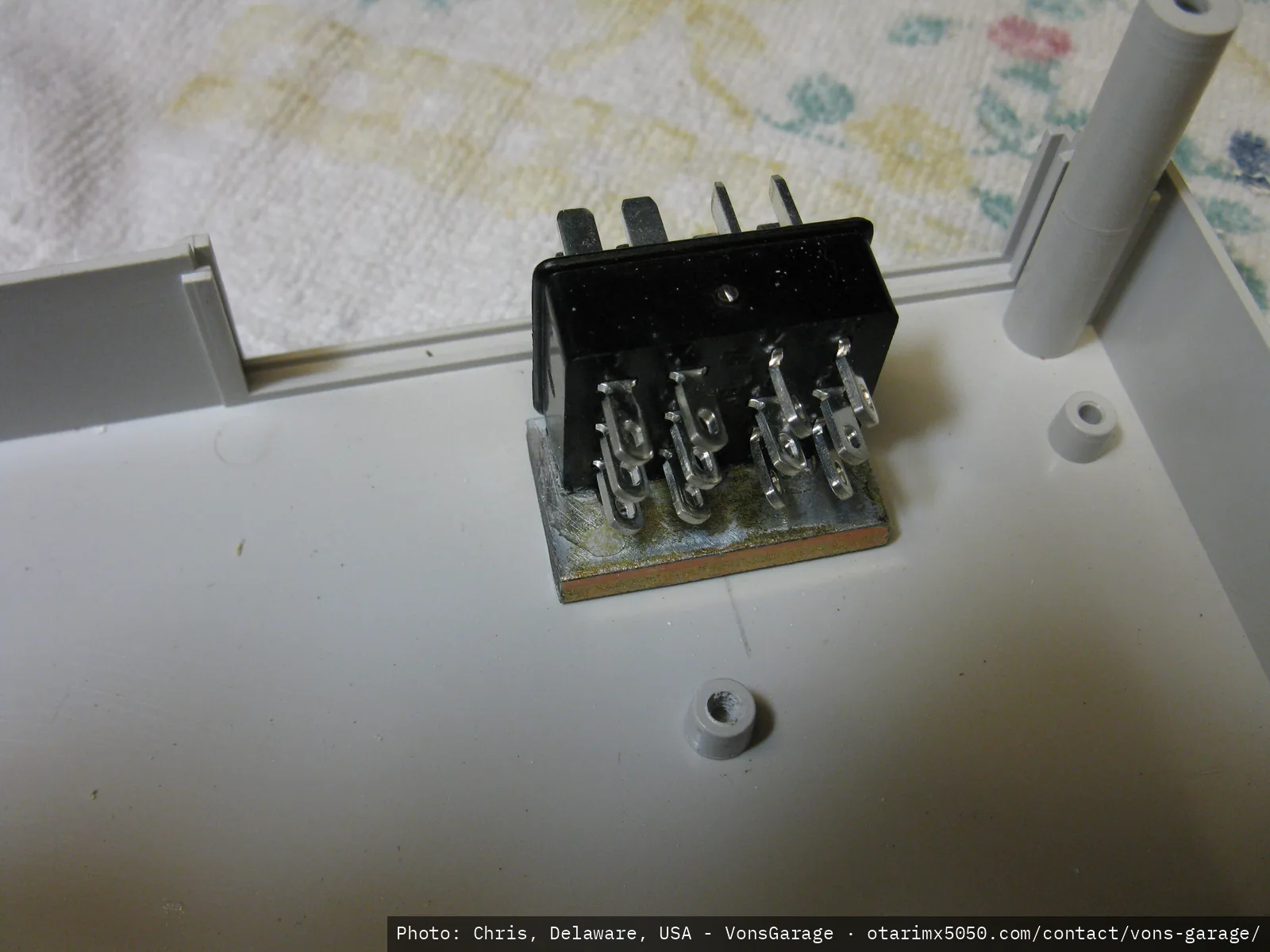 First version: remote control connector, rear view